
Alinco DR-135 Manuals
Manuals and User Guides for Alinco DR-135. We have 7 Alinco DR-135 manuals available for free PDF download: Service Manual, Dealer's Manual
Advertisement
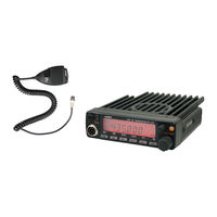
Alinco DR-135 Service Manual (71 pages)
Brand: Alinco
|
Category: Car Receiver
|
Size: 7 MB
Table of Contents

Advertisement

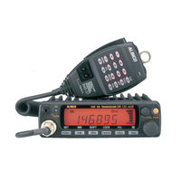
Alinco DR-135 Service Manual (60 pages)
Brand: Alinco
|
Category: Transceiver
|
Size: 3 MB
Table of Contents


Alinco DR-135 Dealer's Manual (20 pages)
VHF FM MOBILE TRANSCEIVER
Brand: Alinco
|
Category: Transceiver
|
Size: 0 MB
Table of Contents
Advertisement