Alinco DR-135 Dealer's Manual
Vhf fm mobile transceiver
Hide thumbs
Also See for DR-135:
- Service manual (71 pages) ,
- Service manual (71 pages) ,
- Service manual (60 pages)
Table of Contents
Advertisement
Quick Links
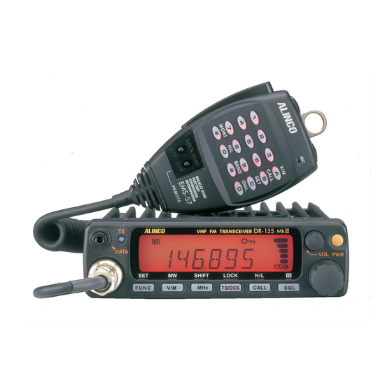
VHF FM MOBILE TRANSCEIVER
Dealer's Manual
Alinco's DR-135 transceivers support the
Channel Indication mode (User's mode),
which protects dealer-defined parameter
settings from being changed by the user.
This manual describes the functions available
in the Channel Indication mode and the
procedures for configuring the transceiver. It
also covers the instructions for installing and
using the DR-135 Channel Data Editor
software.
For information about programming manually,
see the instruction manual provided with the
product
Advertisement
Table of Contents

Related Manuals for Alinco DR-135


Summary of Contents for Alinco DR-135
- Page 1 This manual describes the functions available in the Channel Indication mode and the procedures for configuring the transceiver. It also covers the instructions for installing and using the DR-135 Channel Data Editor software. For information about programming manually, see the instruction manual provided with the...
-
Page 2: Table Of Contents
Setting UP the Transceiver with the Pad BP4 Setting Up the Transceiver with the CH Data Editor Setting UP the Transceiver with the EJ-39D trunking logic board. 3 DR-135 Channel Data Editor Installing the Data Editor Starting the Data Editor... -
Page 3: Channel Indication Mode
1. Channel Indication Mode When the transceiver is in the Channel Indication mode, some functions are completely disabled, some are programmable only with the Channel Data Editor software (not programmable with the transceiver switches), and others are left available. The following table lists the functions provided with the DR- 135 transceiver. -
Page 4: Configuring The Transceiver As A Channel-Indication-Mode Unit
• Setting the pad (BP4) on the printed circuit board of the transceiver (see “2.1 Setting Up the Transceiver with the Pad BP4”); OR • Using the DR-135 Channel Data Editor (see “2.2 Setting Up the Transceiver with the Data Editor”). -
Page 5: Setting Up The Transceiver With The Pad Bp4
Instruction Manual: for information about these parameters, see “Appendix A” on page 15. To set up the DR-135 On the transceiver, set the channel data and store the changes in memory, as needed. -
Page 6: Setting Up The Transceiver With The Ch Data Editor
“Channel” option in the “Indication Mode” field. Write your changes in the transceiver memory. The transceiver will then enter the Channel Indication mode. For more information about using the software, see chapter 3 “DR-135 Channel Data Editor”. -
Page 7: Setting Up The Transceiver With The Ej-39D Trunking Logic Board
2.3 Setting UP the Transceiver with the EJ-39D trunking logic board. 1. Turn the transceiver off. 2. Remove the bottom cover. Connect the EJ-39D to CN101 on the DR-135 circuit board. 3. Refit the bottom cover in the proper position. -
Page 8: Dr-135 Channel Data Editor
3. DR-135 Channel Data Editor The DR-135 Channel Data Editor is used to edit data, which includes the operation parameters for the transceiver and the settings for each channel. This software is useful when you wish to program two or more transceivers in similar ways;... -
Page 9: Setting The Channel Data (Main Menu)
To start the DR-135 Data Editor, at the DOS prompt, type: DR135.EXE DR135.EXE DR135.EXE DR135.EXE DR135 DR135 DR135 DR135 The main menu will appear. Note: • To exit the Data Editor, press the F2 key, select the “Quite Editor (Q)”... - Page 10 Rx Freq: Set the reception frequency. CTCSS / DCS: Set the CTCSS/DCS decoder frequency. Use the Space key to select CTCSS/DCS-off. Press the Enter key from the selected mode to open the “CTCSS tone or DCS code selection screen”. W/N: Set the operating mode (Wide/Narrow).
-
Page 11: Changing The Transceiver Settings
3.4 Changing the Transceiver Settings You can also set the transceiver parameters to stay on throughout the transceiver operation regardless of the channel currently selected. 1) On the main menu, press the F3 key, 2) select the “Radio Option (R)” option and press the Enter key to open the “Edit option data”... -
Page 12: Setting Auto Diaier Memories
Time out timer: Turn the TOT (Time Out Timer) off, or select a transmission time by pressing the space bar. You can reverse the order of the options by holding down the Shift key and pressing the space key. The time out timer starts working when the key is pressed. - Page 13 Note: • To exit the Data Editor, press the F2 key, select the “Quite Editor (Q)” option, and type Y. Setting the Channel Data(Main Menu)for Trunking Only following items can be programmed in Data Editor (Trunking mode). CH Data Edtor Version 1.00 Trunking Mode BANK-Ch: Select the desired channel (from 1-01 through 1-16), (from 2-01 through 2-16) (from 3-01 through 3-16), (from 4-01 through 4-...
-
Page 14: Writing The Data In The Transceiver
Changing the Editor option data for Trunking. Set followings by F3 key in main menu. SQL No: Selects the initial setting value for the squelch level. TX POWER: Select the output power. APO: Turn the auto-power-off feature on or off. LAMP Mode: Set the lighting mode (High or Low). -
Page 15: Reading The Existing Data From The Transceiver
3.8 Reading the Existing Data from the Transceiver You can read the data currently stored in the transceiver memory. Caution: • Make sure the COM port (Dsub connector) on the PC is connected to the external speaker jack on the radio with the interface cable (ERW- 4 or ERW-4C). -
Page 16: Operation With Ej-39D
4. Operation with EJ-39D After Installation of EJ-39D, some function and operation will be changed as follows: TX power Change: Press the CALL key. (at Enable setting) BANK Change: Press the V/M key. Group Change: Press the MHz key. Conventional Mode: Press the TS/DCS key. -
Page 17: Automatic Numbering Identification (Ani)
Appendix A A.1 Automatic Numbering Identification (ANI) This feature allows the transceiver to automatically send the programmed DTMF codes (up to 16 digits) just after the key is pressed and/or released so that the base station can identify the unit. Two auto dialer memories, Nos. -
Page 18: Displayable Characters
A.3 Displayable Characters List of Alphanumeric characters for Name operation Note: • Display in ( ) is the P.C. Display when inputting from PC CH Data Editor. Input pushing Shift key. - Page 20 Phone: 06-6946-8150 Fax: 06-6946-8175 E-mail: export@alinco.co.jp U.S.A : 438 Amapola Avenue,Suite 130,Torrance,CA 90501,U.S.A Phone:310-618-8616 Fax:310-618-8758 http://www.alinco.com/ Germany : Eschborner Landstrasse 55,60489 Frankfurt am Main,Germany Phone:069-786018 Fax:069-789-60766 Dealer / Distributor © Copyright 2000 Alinco, Inc. Osaka Japan Printed in Japan PM0062...
Need help?
Do you have a question about the DR-135 and is the answer not in the manual?
Questions and answers