
Subscribe to Our Youtube Channel
Related Manuals for REMEHA HMI Gas 610 ECO PRO


Summary of Contents for REMEHA HMI Gas 610 ECO PRO
- Page 1 Great Britain Control panel HMI Gas 310/610 ECO PRO Installation, User and Service Manual 125482-03...
-
Page 2: Table Of Contents
Contents Introduction ....................4 Symbols used ............4 Abbreviations ............4 General ..............4 1.3.1 Manufacturer's liability ..........4 1.3.2 Installer's liability .............5 1.3.3 User's liability ............5 Safety instructions and recommendations ..........6 Safety instructions ..........6 Recommendations ..........6 Technical description ................7 Control panel ............7 3.1.1 Functions of the keys ..........7 3.1.2 Meaning of the symbols on the display ....8 Installation ....................9... - Page 3 Contents Troubleshooting ..................22 Shutdowns and lock-outs ........22 6.1.1 General ..............22 6.1.2 Blocking ..............22 6.1.3 Lock out ..............24 Error memory ............27 6.2.1 Error readout memorised ........28 6.2.2 Deletion of the error display ........29 051112 - 125482-03...
- Page 4 051112 - 125482-03...
-
Page 5: Introduction
HMI Gas 310/610 ECO PRO 1. Introduction Introduction Symbols used In these instructions, various danger levels are employed to draw the user's attention to particular information. In so doing, we wish to safeguard the user's safety, obviate hazards and guarantee correct operation of the appliance. -
Page 6: Installer's Liability
1. Introduction HMI Gas 310/610 ECO PRO In the interest of customers, we are continuously endeavouring to make improvements in product quality. All the specifications stated in this document are therefore subject to change without notice. Our liability as the manufacturer may not be invoked in the following cases: 4 Failure to abide by the instructions on using the appliance. -
Page 7: Safety Instructions And Recommendations
HMI Gas 310/610 ECO PRO 2. Safety instructions and recommendations Safety instructions and recommendations Safety instructions Strictly follow the safety instructions given. WARNING This equipment operates using electricity. Disconnect the equipment from the power supply before making electrical connections. Only qualified professionals are authorised to work on the appliance and the installation. -
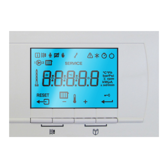
Page 8: Technical Description
3. Technical description HMI Gas 310/610 ECO PRO Technical description Control panel For operation of the boiler Gas 610 ECO PRO: Each module has its own instrument panel. 3.1.1. Functions of the keys Display > [Escape] or J key D Heating temperature key or [-] [+] key S [Enter] or cancel d Key lock-out ºCºFh... -
Page 9: Meaning Of The Symbols On The Display
HMI Gas 310/610 ECO PRO 3. Technical description 3.1.2. Meaning of the symbols on the display Information menu: On/Off switch (0/1): Reading the various current values. After 5 lock-outs, the boiler must be switched off/on again. Chimney-sweeping position: Shunt pump: Forced full or part load for CO measurement. -
Page 10: Installation
4. Installation HMI Gas 310/610 ECO PRO Installation Control panel assembly The instrument panel HMI GAS 310/610 ECO PRO is standard fitted in the Gas 310/610 ECO PRO boiler. 051112 - 125482-03... -
Page 11: Commissioning
HMI Gas 310/610 ECO PRO 5. Commissioning Commissioning Switch on the instrument panel For operation of the boiler Gas 610 ECO PRO: The features and instructions described are for each boiler module. The instrument panel HMI GAS 310/610 ECO PRO is ready for use, as soon as the power to the boiler is switched on. -
Page 12: Reading Out Measured Values
5. Commissioning HMI Gas 310/610 ECO PRO Reading out measured values For operation of the boiler Gas 610 ECO PRO: The features and instructions described are for each boiler module. 5.2.1. Reading the various current values The following current values can be read off the information menu 4 5t = State. -
Page 13: Readout From The Hour Counter And Percentage Of Successful Starts
HMI Gas 310/610 ECO PRO 5. Commissioning 5.2.2. Readout from the hour counter and percentage of successful starts 1. Press the two keys f simultaneously and then key [+] until the symbol \ flashes on the menu bar. 2. Press the S key. hr and the number of hours of boiler operation 3600 (for example) are displayed alternately. -
Page 14: Changing The Settings
5. Commissioning HMI Gas 310/610 ECO PRO State 5t Sub-status 5v 30 Temperature control 31 Limited temperature control (ΔT safety) 32 Output control 33 Increase protection level 1 (Modulate down) 3 Burner for central heating operation 34 Increase protection level 2 (Part load) 35 Increase protection level 3 (Blockage) 36 Modulate up for flame control 37 Temperature stabilisation time... - Page 15 HMI Gas 310/610 ECO PRO 5. Commissioning Factory setting Gas 310 ECO PRO Parameter Description Adjustment range 285 355 430 500 575 650 0 = Simple 1 = Comprehensive 2 = Automatic switching to simple after 3 Display screen minutes 3 = Automatic switching to simple after 3 minutes;...
- Page 16 5. Commissioning HMI Gas 310/610 ECO PRO Factory setting Gas 310 ECO PRO Parameter Description Adjustment range 285 355 430 500 575 650 Release waiting time 0 to 255 seconds Gas valve leak proving 0 = Not connected system VPS 1 = Connected (Accessory) 0 = Off...
- Page 17 HMI Gas 310/610 ECO PRO 5. Commissioning n Boiler type Gas 610 ECO PRO Factory setting Gas 610 ECO PRO Parameter Description Adjustment range 570 710 860 1000 1150 1300 Supply temperature: T 20 to 90 °C 1 to 98 minutes Post-circulation of the pump 99 minutes = continuous 0 = Heating deactivated...
- Page 18 5. Commissioning HMI Gas 310/610 ECO PRO Factory setting Gas 610 ECO PRO Parameter Description Adjustment range 570 710 860 1000 1150 1300 Minimum gas pressure 0 = Not connected check Gps 1 = Connected (Accessory) Hydraulic valve running time HdV 0 to 255 seconds (If connected) Flue gas damper running...
-
Page 19: Modification Of The User-Level Parameters
HMI Gas 310/610 ECO PRO 5. Commissioning 5.3.2. Modification of the user-level parameters Parameters p1 to p5 can be changed by the user. CAUTION Modification of the factory settings may be detrimental to the functioning of the appliance. 1. Press the two keys f simultaneously and then key [+] until the symbol W flashes on the menu bar. -
Page 20: Setting The Maximum Heat Input For Central Heating Operation
5. Commissioning HMI Gas 310/610 ECO PRO 8. If necessary, set other parameters by selecting them using the [-] or [+] keys. 9. Press the > key 2 times to return to the current operating mode. The boiler also returns to operating status if no keys are pressed for 3 minutes. -
Page 21: Return To The Factory Settings
HMI Gas 310/610 ECO PRO 5. Commissioning 5.3.5. Return to the factory settings CAUTION By restoring the factory settings, customized settings can also be erased. So first write down all the customized parameters (eg settings for attached accessories such as a flue gas valve or gas leak control). -
Page 22: Setting The Manual Mode
5. Commissioning HMI Gas 310/610 ECO PRO 5.3.7. Setting the manual mode In some cases it may be necessary to switch the boiler to manual operation, For example, if the controller has not yet been connected. The boiler can be switched to automatic or manual operation under the symbol E. -
Page 23: Troubleshooting
HMI Gas 310/610 ECO PRO 6. Troubleshooting Troubleshooting Shutdowns and lock-outs For operation of the boiler Gas 610 ECO PRO: The features and instructions described are for each boiler module. 6.1.1. General The boiler is fitted with an electronic regulation and control unit. The heart of the control system is a microprocessor, the Comfort ©... - Page 24 6. Troubleshooting HMI Gas 310/610 ECO PRO Shutdown Description Probable causes Checking / solution code The maximum temperature Check the circulation (direction, pump, increase speed tolerated in Non-existent or insufficient valves) 5v[4 the exchanger has been circulation Reasons for the heat demand exceeded Check the circulation (direction, pump, valves)
-
Page 25: Lock Out
The error code is important for rapid and correct tracking of the type of problem and for any technical assistance from Remeha. Error Description Probable causes Checking / solution... - Page 26 6. Troubleshooting HMI Gas 310/610 ECO PRO Error Description Probable causes Checking / solution code Check the wiring Vent the air in the heating system Bad connection Check the circulation (direction, pump, valves) Temperature of heat No circulation Check the water pressure e[04 exchanger too low Sensor not or badly...
- Page 27 HMI Gas 310/610 ECO PRO 6. Troubleshooting Error Description Probable causes Checking / solution code Check cabling of ignition transformer Check the ionization/ignition electrode No ignition Check breakdown to earth Check the earthing Defective control SU PCB Check that the air inlet and flue gas discharge flues are not blocked Check that the gas valve is fully opened Check the supply pressure...
-
Page 28: Error Memory
6. Troubleshooting HMI Gas 310/610 ECO PRO Error Description Probable causes Checking / solution code Purge the gas supply to remove air Check that the gas valve is fully opened Check the supply pressure No or insufficient ionization 5x Flame loss e[36 Check the operation and setting of the gas valve unit current... -
Page 29: Error Readout Memorised
HMI Gas 310/610 ECO PRO 6. Troubleshooting 6.2.1. Error readout memorised 1. Press the two keys f simultaneously and then key [+] until the symbol c flashes on the menu bar. 2. Select the installers menu using the key S . c0de appears on the display. -
Page 30: Deletion Of The Error Display
6. Troubleshooting HMI Gas 310/610 ECO PRO 6.2.2. Deletion of the error display 1. Press the two keys f simultaneously and then key [+] until the symbol c flashes on the menu bar. 2. Select the installers menu using the key S . c0de appears on the display. - Page 31 HMI Gas 310/610 ECO PRO 6. Troubleshooting 051112 - 125482-03...
- Page 32 6. Troubleshooting HMI Gas 310/610 ECO PRO 051112 - 125482-03...
- Page 33 HMI Gas 310/610 ECO PRO 6. Troubleshooting 051112 - 125482-03...
- Page 36 Remeha Commercial UK - Part of the BDR THERMEA Remeha House Molly Millars Lane Wokingham Berks RQ41 2QP After Sales Tel: 01189743076 Technical Enquires: 01189743067 Internet: www.remeha.co.uk © Copyright All technical and technological information contained in these technical instructions, as well as any drawings and technical descriptions supplied, remain our property and shall not be multiplied without our prior consent in writing.
Need help?
Do you have a question about the HMI Gas 610 ECO PRO and is the answer not in the manual?
Questions and answers