Table of Contents
Advertisement
Quick Links
Advertisement
Table of Contents

Subscribe to Our Youtube Channel
Related Manuals for REMEHA HMI S-Control


Summary of Contents for REMEHA HMI S-Control
- Page 1 England Installation and user manual Control panel HMI S-Control...
- Page 2 Dear Customer, Thank you very much for buying this appliance. Please read through the manual carefully before using the product, and keep it in a safe place for later reference. In order to ensure continued safe and efficient operation we recommend that the product is serviced regularly. Our service and customer service organisation can assist with this.
-
Page 3: Table Of Contents
Contents Contents Safety ................... . 4 Liabilities . -
Page 4: Safety
1 Safety Safety Liabilities 1.1.1 Manufacturer's liability Our products are manufactured in compliance with the requirements of the various Directives applicable. They are therefore delivered with the marking and any documents necessary. In the interests of the quality of our products, we strive constantly to improve them. We therefore reserve the right to modify the specifications given in this document. -
Page 5: About This Manual
2 About this manual About this manual Additional documentation This manual forms part of the documents pack supplied with the boiler. Symbols used 2.2.1 Symbols used in the manual This manual uses various danger levels to draw attention to special in structions. -
Page 6: Technical Specifications
3 Technical specifications Technical specifications Homologations 3.1.1 Directives This product complies with the requirements of the following European Di rectives and Standards: 2006/95/EC Low Voltage Directive 2004/108/EC Electromagnetic Compatibility Directive 7616014 - v.03 - 15022016... -
Page 7: Control Panel Description
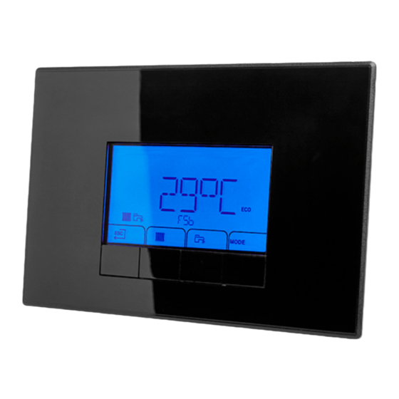
4 Control panel description Control panel description Description of the keys Fig.1 Control panel keys 1 ESC ( ) or 2 Heating temperatures 3 Domestic hot water temperatures or VALIDATION ( ) key 4.1.1 Key functions Fig.2 Function keys Back to the previous level without saving the modifications made Manual reset Accessing the heating parameters Lowering the value... -
Page 8: Commissioning
5 Commissioning Commissioning Switching on the control panel The HMI S-control control panel is ready for use as soon as the power to the boiler is switched on. The start-up program starts and cannot be interrupted. Start program Various short items of information appear on the screen during start-up. -
Page 9: Operation
6 Operation Operation Use of the control panel 6.1.1 Browsing in the menus Fig.3 Activating the screen 1. Press any key to activate the screen. The main display with time and day number appears. MW-3000377-01 Fig.4 Accessing the menus 2. Press the two keys on the right simultaneously to access the menu level. -
Page 10: Setting The Time And Language
6 Operation Setting the time and language Note First set the desired language, then the correct time, day and date before further use of the control panel. 6.2.1 Setting the language 1. Navigate to the User menu. Fig.11 Accessing the User menu 2. -
Page 11: Shutdown
6 Operation Fig.21 Changing the time 6. Press the keys to modify the time. 7. Press the key to confirm the value. 8. Press the key repeatedly to access the following menu options. 9. Press the key twice to go back to the main display. MW-3000355-01 Shutdown 6.3.1 Switching off the central heating... -
Page 12: Settings
7 Settings Settings Parameter descriptions Tab.3 Factory settings for user level parameters Parameter Description Adjustment range Quinta Ace160 Activate manual mode 0 = Off 1 = On (with flow temperature set point in manual mode) 2 = Weather-compensated (flow temperature in ac cordance with heating curve) Activate CH 0 = Off... - Page 13 7 Settings Parameter Description Adjustment range Quinta Ace160 Minimum water pressure WPS 0 - 7 bar 0 = No minimum Release waiting time 0 to 255 seconds Service burning hours 0 - 51,000 17,400 Maintenance message 0 = maintenance message off 1 = maintenance message on 2 = maintenance message A, B, C Service operating hours...
- Page 14 7 Settings Parameter Description Adjustment range Quinta Ace160 Gas leakage control VPS 0 = not connected 1 = connected Minimum anti-cycle time of burner 0 to 20 minutes CH part load time 5 to 180 seconds Post-circulation of the pump (CH) 1 to 98 minutes 99 = Continuous Maximum pump speed for CH...
-
Page 15: Setting The Parameters
7 Settings Setting the parameters 7.2.1 Changing user parameters The parameters in the User menu can be modified by the user to meet central heating and domestic hot water comfort requirements. Caution Changing the factory settings may adversely affect the operation of the boiler. -
Page 16: Changing The Dhw Temperature
7 Settings Fig.37 Return to the main display 5. To go back to the main display, press the key once. MW-3000370-01 7.2.3 Changing the DHW temperature Fig.38 Selecting DHW temperature 1. Press the key to select the DHW flow temperature. The set DHW temperature appears on the screen. -
Page 17: Changing Installer Parameters
7 Settings Fig.47 Selecting the day 6. Select the required day number by keeping the key pressed until the symbol for the required day flashes. Confirm by pressing key. Day selected Description MW-3000360-01 Every day of the week Monday Tuesday Wednesday Thursday Friday... -
Page 18: Setting The Maximum Output For Central Heating
7 Settings Caution Changing the factory settings may adversely affect the operation of the boiler. 1. Navigate to the Installer menu. Note The Installer menu is available only when the icon flashes. Fig.50 Navigating to the Installer menu 2. Press the key to open the Installer menu. -
Page 19: Restoring To Factory Settings
7 Settings Fig.58 Output Quinta Ace - 160 M Maximum output F Factory setting Q Heat output (kW) R Fan rotation speed (rpm) 1000 2000 3000 4000 5000 6000 7000 8000 AD-3000801-01 7.2.7 Restoring to factory settings 1. Navigate to the Installer menu. Note The Installer menu is available only when the icon flashes. -
Page 20: Resetting The Maintenance Message
7 Settings 7.2.8 Resetting the maintenance message Reset the maintenance message once the stated maintenance service has been carried out. 1. Navigate to the Counter menu. Fig.68 Accessing the Counter menu 2. Press the key to open the Operating hours/Timer Program/Time display menu. -
Page 21: Changing The Scb-01 Pcb Parameters
7 Settings Fig.78 Back to the main display 6. Press the key twice to go back to the main display. Manual mode is switched off. MW-3000305-01 7.2.11 Changing the SCB-01 PCB parameters 1. Navigate to the icon to select the PCB connected. Fig.79 Navigating to the PCBs connected 2. -
Page 22: Reading Out Current Values
7 Settings 1. Navigate to the Installer menu. Note The Installer menu is available only when the icon flashes. Fig.89 Accessing the Installer menu 2. Press the key to open the Installer menu. MW-3000312-01 Fig.90 Entering the code 3. Keep pressing the key until the code is displayed. -
Page 23: Status And Sub-Status
7 Settings Value Description Unit Software version Parameter version 7.3.1 Status and Sub-status The information menu gives the following status and sub-status num bers: Tab.7 Status numbers Status Stand-by mode Boiler start (heat demand) Burner start Burners active in CH or DHW mode Burner stop Boiler stop (end of heat demand) Control stop... -
Page 24: Reading Out The Water Pressure And Flow Temperature
7 Settings Sub-status Burner off Post ventilation Close flue gas damper/external gas valve Recirculation protection Stop fan Limited power Pump post circulation Pump off Start anti-swing Blocking code Lock out code Reading out the water pressure and flow temperature Fig.95 Displaying the water pressure and 1. - Page 25 7 Settings Parameter Description Unit Number of boiler operating hours Number of boiler operating hours since last service Number of hours of rotation of circulation pump Number of hours boiler working for central heating Number of successful starts – Energy consumption for CH operation Energy consumption for DHW operation Number of circulation pump starts –...
-
Page 26: Troubleshooting
8 Troubleshooting Troubleshooting Blocking A (temporary) blocking mode is a boiler status, resulting from an abnormal state. The display shows a blocking code (for example ) to gether with the symbol. The control unit makes a number of attempts to start the boiler again. -
Page 27: Lock Out
8 Troubleshooting Blocking code Description Flow temperature sensor above normal range (high-limit thermostat): Bad connection: check the wiring and connectors. Incorrectly fitted sensor: check that the sensor has been correctly fitted Faulty sensor: replace the sensor No flow or insufficient flow: Check the circulation (direction, pump, valves) Check the water pressure Check the cleanliness of the heat exchanger... -
Page 28: Error Codes
8 Troubleshooting Note The error code is needed to find the cause of the error quickly and correctly and for any support from Remeha. Press the key for two seconds. If the error code continues to display, search for the cause in the error table and apply the solution. - Page 29 8 Troubleshooting Error code Description CSU time out: Bad connection: check the wiring and connectors. Faulty CSU: replace CSU Communication error with the safety PCB: Bad connection: check the wiring and connectors. Control unit failure: replace the control unit Safety parameters not OK: Bad connection: check the wiring and connectors.
-
Page 30: Warning
8 Troubleshooting Error code Description Gas valve fault: Bad connection: check the wiring and connectors. Faulty gas valve: replace the gas valve Warning If it is anticipated that a situation may develop into a fault, the boiler will first give a warning for some malfunctions. The error code is displayed as follows: In a red flashing display: the symbol... -
Page 31: Clearing The Error Memory
8 Troubleshooting Fig. Accessing the Failure menu 2. Press the key to open the Error menu. Note The Failure menu is available only if the icon flashes. MW-3000317-01 Fig. Viewing error messages 3. Press the key to view the error messages. XX is the number of stored error messages. - Page 32 8 Troubleshooting 7616014 - v.03 - 15022016...
- Page 33 8 Troubleshooting 7616014 - v.03 - 15022016...
- Page 34 8 Troubleshooting 7616014 - v.03 - 15022016...
- Page 35 © Copyright All technical and technological information contained in these technical instructions, as well as any drawings and technical de scriptions supplied, remain our property and shall not be multiplied without our prior consent in writing. Subject to alterations.
- Page 36 Remeha Commercial UK Innovations House 3 Oaklands Business Centre Oaklands Park RG41 2FD Wokingham Tel: +44 (0)118 978 3434 Fax: +44 (0)118 978 6977 Internet: www.remeha.co.uk E-mail: boilers@remeha.co.uk 7616014 - v.03 - 15022016 7616014...
Need help?
Do you have a question about the HMI S-Control and is the answer not in the manual?
Questions and answers