Advertisement
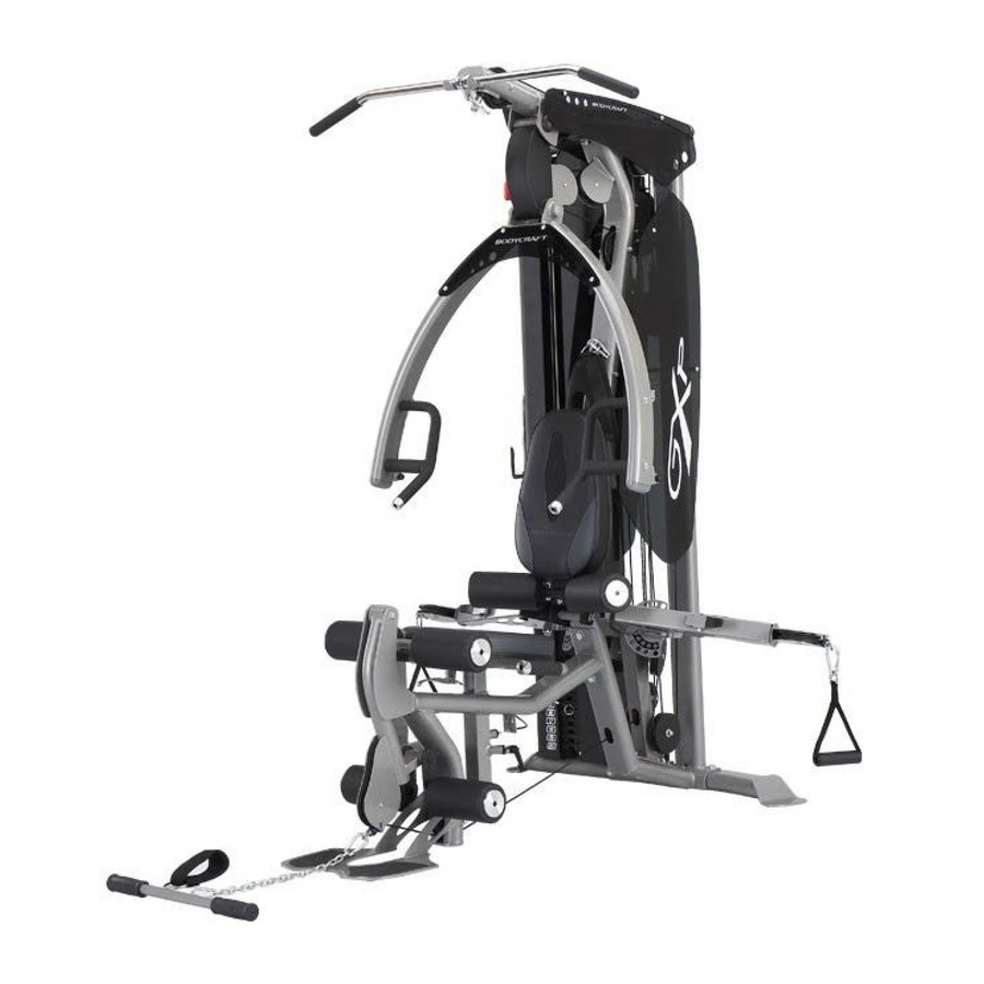
THE GXP STRENGTH TRAINING SYSTEM
ASSEMBLY INSTRUCTION
QUESTION?
As a quality home gym supplier we are committed to your complete satisfaction. If you have
questions, or find missing or damaged parts, we will guarantee your complete satisfaction through
our authorized dealer service centers or our home office customer service department. Please call
your local dealer for assistance or BodyCraft at 800-990-5556 (9:00 AM - 5:00 PM). Our trained
technicians will provide immediate assistance to you, free of charge.
Bodycraft is a division of Recreation Supply Inc.
P.O. BOX 181
Sunbury, OH 43074
MA709
Advertisement
Chapters
Table of Contents

Related Manuals for BodyCraft GXP


Summary of Contents for BodyCraft GXP
-
Page 1: Assembly Instruction
Please call your local dealer for assistance or BodyCraft at 800-990-5556 (9:00 AM - 5:00 PM). Our trained technicians will provide immediate assistance to you, free of charge. -
Page 2: Before You Begin
For your safety and benefit, read this manual and the accompanying literature before using the Bodycraft GXP. Keep this manual for future reference. If you have additional questions, please call your local Bodycraft GXP dealer or our customer service department at 800-990-5556 Monday through Friday, 9 a.m. - Page 3 76 76 144 135 137 112 63 91 139 116 132 152 EXPLODED...
- Page 4 PARTS LIST NO. DESCRIPTION QTY. MAIN FRAME TOP FRAME REAR STABILIZER SEAT FRAME FOOT PLATE GUIDE ROD PRESS ARM RIGHT HANDLE OF PRESS ARM LEFT HANDLE OF PRESS ARM PRESS ARM SUPPORT SEAT ADJ. HANDLE SEAT ADJ. FRAME SEAT BACK ADJUSTER LEG HOLDER METAL HINGE CABLE ARM...
- Page 5 PARTS LIST NO. DESCRIPTION QTY. RIGHT SIDE ACRYLIC PANEL LEFT SIDE ACRYLIC PANEL RIGHT TOP PANEL LEFT TOP PANEL PULLEY DECORATION PANEL PRESS ARM PANEL LONGER TOP PANEL TRIM SHORTER TOP PANEL TRIM SELECTOR ROD TOP PLATE WEIGHT PLATE AB CRUNCH ANKLE STRAP SINGLE HANDLE SEAT PAD...
- Page 6 PARTS LIST NO. DESCRIPTION QTY. BEARING BASIN (all pre-assembled) BEARING (all pre-assembled) BEARING COVER (all pre-assembled) SEALING RING (all pre-assembled) LONGER RED POP PIN SHORTER RED POP PIN TIGHTEN KNOB 1/2" X 3-1/4" HEX BOLT 1/2" X 3" HEX BOLT 1/2"...
- Page 7 STEP 1 ASSEMBLE MAIN FRAME To ease the assembly process, Do Not tighten bolts until instructed. You need two people to help you assemble GXP gym. 1. Attach Rear Stabilizer (3) to Main Frame (1), using two 1/2" X 1-1/2" Bolts (105), two 1/2" Smaller Washers (136).
- Page 8 STEP 2 ASSEMBLE CABLE ARM ASSEMBLY Remember to keep all BOLTS loose to ensure the holes will align easily. 1. Attach the Cable Arm Assembly (17) to the threaded bolts welded on the bottom of the Main Frame (1) using two 1/2" Smaller Washers (136) and two 1/2" Nylon Nuts (144). 2.
-
Page 9: Main Frame
STEP 3 ASSEMBLE TOP FRAME 1. Attach Leg Extension Arm with bearing pre-installed (19) to Seat Frame (4), by aligning the hole and inserting Leg Extension Axle (29). Fasten Leg Extension Axle (29), using two 5/16" X 5/8" Inner Hex Screws (116), two 5/16" Washers (138), two 5/16" Spring Washers (139). Check to ensure the Leg Extension Arm (19) pivots freely. -
Page 10: Press Arm Support
STEP 4 ASSEMBLE PRESS ARM AND SEAT & BACK PAD 1. Attach the Press Arm Support (9) to the Top Frame (2) by aligning the holes and inserting the Axle (27). Secure the Axle (27) using two 1/2" Larger Washers (135), and two 1/2" Nylon Nuts (144). - Page 11 STEP 4 ASSEMBLE PRESS ARM AND SEAT & BACK PAD...
- Page 12 STEP 5 INSTALL TOP CABLE TOP CABLE (66) Threaded End Ball End Make certain long Pin Bolt is inserted completely through both holes in the pulley bracket. Failure to do so will result in improper alignment and the pulley will rub on steel. Assemble cables and Pulleys simultaneously 1.
- Page 13 STEP 5 INSTALL TOP CABLE T1,T2 STEP 2-1 T3,T4,T5 STEP 2-2 T6,T7,T8 T9,T10 T11,T12,T13,T14...
-
Page 14: Cable Arm
STEP 6 INSTALL AB CRUNCH CABLE AB CRUNCH CABLE (67) REMOVABLE END (67A) Removable End of AB Cunch Cable should be screwed into completely after the AB Crunch Ccable installment. 1. Run the threaded end of the AB Crunch Cable (67) underneath the slot of pulley A1 mounted on Leg Extension Arm (19), under pulley A2 mounted at the bottom hole of Seat Frame (4), using one each 3/8"... - Page 15 STEP 7 INSTALL CONNECT CABLE CONNECT CABLE (68) Threaded End Threaded End 1. Screw one threaded end of the Connect Cable (68) into the Adj. Floating Pulley Block (23) about half way as Fig. C1. Then run cable up and around pulley C2 mounted on the bottom of the Double Pulley Block (22), using 3/8"...
- Page 16 STEP 8 INSTALL CABLE ARM CABLE CABLE ARM CABLE (69) Ball End Ball End 1. The Cable Arm Cable (69) is already run through the Cable Arm (15). Mount Pulley P3 and P7 along with their Pulley Guide Brackets (26) to the Cable Arm Assembly (17) as shown, using one 3/8"...
- Page 17 5. Attach Pulley Cover Panel (42) on the rear top of Main Frame (1), using four M6 X 12L Male Screws (124). 6. Attach Lat Bar (37), Curl Bar (36), Single Handle (50) and AB Crunch Belt (48) to the GXP Strength Training System.
- Page 18 STEP 9 WEIGHT STACK SHROUD & ACRYLIC PANEL...
-
Page 19: Adjustable Pulley Block
The Cable Adjustment of GXP GYM a. The Cables should be tightened to the point just before the Top Plate lifts off the stack. In other words, if the Top Plate is not resting on the stack, you will need to add length, or, if there is slack in the cables, you will need to shorten the cables. -
Page 20: Selector Pin 1
Guide Rods (6). Enjoy many years of a Fit Lifestyle. Thank you for purchasing the BodyCraft GXP Strength Training System. If you have any questions, please call your local BodyCraft dealer, call our customer service department at...
Need help?
Do you have a question about the GXP and is the answer not in the manual?
Questions and answers