Advertisement
Quick Links
1
2
3
4
5
6
7
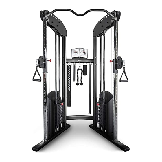
HFT STRENGTH TRAINING SYSTEM
8
9
1 0
1 1
1 2
1 3
1 4
1 5
1 6
1 7
1 8
1 9
Serial Number Location
2 0
2 1
2 2
2 3
2 4
2 5
2 6
2 7
2 8
2 9
3 0
3 1
S E R I A L
1 2 3 4 5 6 7 8
Record your Serial number
and purchase date here:
S/N __________________
DATE:________________
DEALER:______________
______________________
Model No. HFT
MB1303
BODYCRAFT
OWNER'S MANUAL
1
2
3
4
5
6
7
8
9
1 0
1 1
1 2
1 3
1 4
1 5
1 6
1 7
1 8
1 9
2 0
2 1
2 2
2 3
2 4
2 5
2 6
2 7
2 8
2 9
3 0
3 1
Fitness Authority Industrial Co., LTD.
No. 15, Xiangxue Rd., Dali Dist.,
Taichung City 41275, Taiwan.
Advertisement

Related Manuals for BodyCraft HFT


Summary of Contents for BodyCraft HFT
- Page 1 HFT STRENGTH TRAINING SYSTEM OWNER'S MANUAL Serial Number Location S E R I A L 1 2 3 4 5 6 7 8 Record your Serial number and purchase date here: S/N __________________ DATE:________________ DEALER:______________ ______________________ Model No. HFT Fitness Authority Industrial Co., LTD.
- Page 2 30cm on left and right side and at least 15cm in front and rear side. The recommended free area in at least 60cm on every side. 16. If you are unsure about the proper use of the BODYCRAFT HFT Strength Training System call your local BODYCRAFT dealer or our customer service department.
- Page 3 Gym Placement Planner 38" HEIGHT 55" 82" Important Notes and Tips: Recommended Tools 1. Do not tighten bolts until instructed. for Assembly 2. Two people are required for the safe assembly of this product. 3. Use window cleaner or water to assist with sliding roller pads on to tubes.
- Page 4 HFT PARTS LIST 1 NOTE: If you are missing a listed part, it likely has been pre-installed in our factory for quality control purposes. Please con�nue with assembly. *Parts images are not to scale. (2R) UPRIGHT FRAME - RIGHT (1R) BASE FRAME LEG - RIGHT...
- Page 5 HFT PARTS LIST 2 NOTE: If you are missing a listed part, it likely has been pre-installed in our factory for quality control purposes. Please con�nue with assembly. *Parts images are not to scale. (21) 10 LB. WEIGHT (22) RUBBER...
- Page 6 STEP 1 Assemble Upright Frame TWO PEOPLE ARE REQUIRED TO ASSEMBLE THIS STEP. DO NOT TIGHTEN BOLTS UNTIL THE END OF STEP 2. 1. Carefully install two End Caps (38) onto each of the Base Frame Legs (1R & 1L). 2.
- Page 7 STEP 2 Assemble Top Frame TWO PEOPLE ARE REQUIRED TO ASSEMBLE THIS STEP. DO NOT TIGHTEN BOLTS UNTIL THE END OF THIS STEP. 1. Slide Pulley Height Adjusters (15R & 16L) onto the Upright Frames (2R & 3L). 2. Attach Upright Frames (2R & 3L) to the Base Frame Legs (1R & 1L) using four pre-installed 3/8"...
- Page 8 STEP 3 Assemble Guide Rods 1. Insert two Plastic Guide Rod Holders (24) into the outer holes of each of the Base Frame Legs (1L & 1R). Insert two Guide Rods (5) into the Plastic Guide Rod Holders (24). If you have 28 Weights Plates (21) (14/side), install the Stack Spacers (23) onto the guide rods, (If you have 38 weight plates DISCARD Spacers).
- Page 9 STEP 4 Assemble Cable and Pulleys Cable (27) Ball End Bolt End Simultaneously install Cables and Pulleys. 1. Feed the Bolt End of Cable (27) through Rotating Pulley Holder (17) Fig A. Route over the two Pulleys P3 and P4 mounted on the Right Top Frame (6R) Fig B. Route down and around the Pulley Block (18) Pulley P5 Fig C.
- Page 10 STEP 5 Assemble Right & Left Panel 1. Loosely attach Weight Panels (10R & 11L) to the Rear Upright Frames (4) using eight Plastic Studs (43), four 1/4" X 6" Hex Bolts (54), eight 1/4" Washers (66), and four 1/4" Nylon Nuts (70). 2.
- Page 11 STEP 6 Accessories and Exercise Guide Placement 1. Hand two Single Handles (32), Chin Assist Strap (30), Tricep Rope (31), Sport Bar (12), two Chains (33), Ankle Strap (29), and Long Bar (13) on the Top Cross Support (8). 2. Attach Exercise Book (28), Exercise Book Holder (26) with one Plastic Stud (43) to the Top Cross Support (8) using one M4 X 10L Sunken Head Screw (59), one M4 X 40L Sunken Head Screw (58) and two M4 Nylon Nuts (72) as shown.
- Page 12 COMPLETE PARTS CHART NO. DESCRIPTION QTY. BASE FRAME LEG - RIGHT BASE FRAME LEG - LEFT UPRIGHT FRAME - RIGHT UPRIGHT FRAME - LEFT REAR UPRIGHT FRAME GUIDE ROD TOP FRAME - RIGHT TOP FRAME - LEFT CHIN - UP BAR TOP CROSS SUPPORT BOTTOM CROSS SUPPORT WEIGHT PANEL - RIGHT...
- Page 13 COMPLETE PARTS CHART NO. DESCRIPTION QTY. PULLEY PLASTIC BUSHING END CAP 1" X 295L FOAM GRIP 1" X 900L FOAM GRIP SELECTOR PIN SPACER PLASTIC STUDS 1/2" BUSHING BEARING C - RING RUBBER COVER TOP PLATE BOLT 1/2" X 4-1/4" HEX BOLT 3/8"...
-
Page 14: Exploded View
EXPLODED VIEW 51 51 51 51 36 69 63 69 65 36 66 54 66 54... -
Page 15: Maintenance
5. Clean and apply silicone to the Guide Rods every 6 months. Enjoy many years of a Fit Lifestyle. Thank you for purchasing the BODYCRAFT HFT Strength Training System. If you have any questions or comments, please contact your local BODYCRAFT dealer.
Need help?
Do you have a question about the HFT and is the answer not in the manual?
Questions and answers