Table of Contents
Advertisement
Quick Links
DRd Rack Enclosure
Installation Manual
Revision C
C o p y r i g h t © 2 0 1 3 E le c tr o n i c T h e a t r e C o n t r o l s , I n c .
A l l R i g h t s r e s e r v e d .
P r o d u c t in f o r m a t i on a n d s p e c i f i c a t i o n s s u bj e c t t o c h a n g e .
P a r t N u m b e r : 7183M2100 R e v C
R e l e a s e d : D e c e m b e r 2 0 1 3
Advertisement
Table of Contents

Subscribe to Our Youtube Channel
Related Manuals for ETC DRd6-12-120


Summary of Contents for ETC DRd6-12-120
- Page 1 DRd Rack Enclosure Installation Manual Revision C C o p y r i g h t © 2 0 1 3 E le c tr o n i c T h e a t r e C o n t r o l s , I n c . A l l R i g h t s r e s e r v e d .
- Page 2 ® ® ET C , U n i s o n P a r a d i g m ® a n d S m a r t L in k a r e e i t he r r e g i s t e r ed t r a d e m a r k s o r t r a d e m a r k s o f E le c tr o n i c T h e a t r e C o n t r o l s , I n c .
-
Page 3: Table Of Contents
Contacting ETC ........2... - Page 4 3-wire Fluorescent ........30 2-wire Fluorescent ........31 Connect Control Wiring .
-
Page 5: Introduction
Manual when your DRd rack is to be installed with an adjoining auxiliary rack enclosure. DRd12 rack DRd6 rack DRd Series Rack Enclosures Series Voltage Notes DRd6-12-120 120/208 VAC DRd6-12-240 240/415 VAC 6 module rack enclosure for up to 12 circuits. DRd6-12-230 230/400 VAC CE Neutral Disconnect... -
Page 6: Warnings And Notice Conventions
ETC web site at www.etcconnect.com. For technical questions about Unison systems, contact ETC Technical Services directly at one of the offices listed below. Emergency service is available from all ETC offices outside of normal business hours. When calling for assistance, please have the following information handy: •... -
Page 7: Drd Rack Components
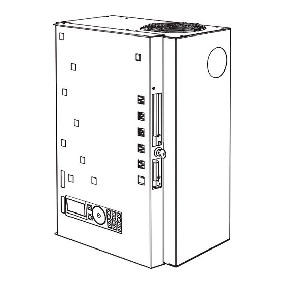
DRd Rack Components Unison DRd racks are available in 6 or 12 module enclosures and are available for an input voltage range of 85-300 VAC, 47-63 Hz. Racks are pre-wired and supplied with three phase, 4 wire and ground, main lugs which are easily converted for split phase, 3 wire and ground, operation without the need for additional materials. - Page 8 • The use of a station power module provides power nd control for architectural control stations. • Use a SmartLink station power module (S-SPM) in a DRd rack enclosure to provide power for up to 16 SmartLink architectural control stations when used with the SmartLink ACP.
-
Page 9: Prepare For Installation
Unpack your order and check the contents against the packing list to be sure your order is complete. Step 4: If you discover a problem, call the ETC Systems Group the closest office of purchase. See “Contacting ETC” on page 2. -
Page 10: Maximum Current Draw Of Racks
Wire bending space limits the feed to the AX12X-MCB rack to 400A maximum. ETC installs a 100% rated two pole breaker (or two poles from a three pole breaker) in the AX12X-MCB, for a total deliverable current of 400A in a single phase (split phase) configuration. -
Page 11: Where To Install The Rack Enclosure
Where to Install the Rack Enclosure Unison DRd rack enclosures are designed to be surface mounted on load bearing walls in an electrical closet or a room with restricted public access. It is recommended that you install the rack at least 36” (915mm) off the floor surface to ensure clear view of the Architectural Control Processor (S-ACP or P-ACP) for programming and operation. -
Page 12: Installation Environment Requirements
Main breakers not in the same room must have a physical means to be locked off. ETC recommends adopting lockout / tagout procedures for your facility and follow appropriate Lockout/ Tagout procedures as described in NFPA Standard 70E. -
Page 13: Control Specifications
DRd rack feed feed feed ETC Console (for optional stage lighting) N o t e : DRd rack enclosures are shipped with the lugs installed in a top feed orientation by default. You may change the lug orientation to a bottom feed as needed. -
Page 14: Control Wire Specification
(1.5mm )wire for grounding when not installed in grounded metal conduit. ETC uses two types of LinkConnect networks, for SmartLink and Paradigm systems. While the wiring for LinkConnect in SmartLink and Paradigm systems are the same, the two communication and control types are not interchangeable. SmartLink products are compatible only with the SmartLink ACP, SmartLink station power module, and SmartLink architectural control stations. - Page 15 DMX can address up to 512 channels of control. DMX is installed in a daisy chain topology and includes one pair of wires (data +, data -) plus an ISO ground. ETC recommends the use of Belden 9729 (or approved equal) wire with a single end of line termination (90- 150).
-
Page 16: Install Rack Enclosures
C h a p t e r 2 Install Rack Enclosures This chapter contains instructions for installation of the DRd rack enclosure. This chapter contains the following sections: • Mounting Individual DRd Rack Enclosures..... . .13 •... -
Page 17: Mounting Individual Drd Rack Enclosures
Mounting Individual DRd Rack Enclosures Unison DRd rack enclosures are designed to be surface mounted on load bearing walls in an electrical closet or a room with restricted public access. Alternatively the DRd rack may be mounted on a pedestal (DRd-Ped). It is recommended that rack enclosures installed on the pedestal floor stand also be secured to the wall for greater stability. -
Page 18: Mounting A Drd Rack Enclosure On A Pedestal
Mounting a DRd Rack Enclosure on a Pedestal The Unison DRd rack pedestal is designed with the same footprint as the Unison dimmer rack. The acceptable conduit access in the bottom of the DRd rack overlaps the floor stand access panel for contractor wiring and installation convenience. It is recommended to secure a DRd rack installed on a pedestal to a wall for greater stability. -
Page 19: Mounting Auxiliary And Drd Rack Enclosures Together
Mounting Auxiliary and DRd Rack Encl osures Together Unison DRd and AX auxiliary rack enclosures are designed to be surface mounted on load bearing walls in an electrical closet or a room with restricted public access. One DRd rack may be bussed to the AX series auxiliary rack, which may contain a main circuit breaker (MCB) or a main lug (ML) for power distribution to the adjacent DRd12 rack. - Page 20 Step 7: Install the ETC supplied 2 1/2” (64mm) nylon insulated chase nipple and 2 1/2” (64mm) locknut between the auxiliary and DRd rack enclosures. Step 8: For cross-bussed DRd12-24 rack installations, install the second DRd12-24 by following steps 4 through 7 above.
-
Page 21: Rough-In Conduit And Wiring
C h a p t e r 3 Rough-in Conduit and Wiring This chapter contains instructions for conduit and wiring installation of the DRd rack enclosure. This chapter contains the following sections: • Prepare the DRd Rack ........18 •... -
Page 22: Prepare The Drd Rack
Prepare the DRd Rack All rack terminations are accessible from the front of the rack. Reference “Wire Routing and Specification”, page 8 for conduit access specifications. Prior to conduit installation you should remove the power supply access panel for clear access to the top of the DRd rack enclosure. -
Page 23: Modify Phase Bus For 120 Vac Split Phase Operation
b: For the ribbon cable connected on the right rear side, release the tabs on either side of the connector by sliding them opposite the connector then gently pull the cable free. c: For the two-wire cable on the right side, gently pull the connector straight out. Step 5: Remove the power supply access panel. - Page 24 b: Remove the red sense wire from phase 2 (L2) and reroute it to the neutral bar. c: Move the second copper strap to connect between phase 2 (L2) and phase 3 (L3). Step 3: For cross-bussed DRd12-48 installations, complete step 2 for both racks. The rack doors have been removed from...
-
Page 25: Rough-In Conduit To The Drd Rack
Rough-in Conduit to the DRd Rack Line feed wires terminate on the main lugs provided. The DRd12 rack is shipped from the factory with the main lugs in a top feed orientation. The lugs can be changed to a bottom feed orientation by removing the lug mounting bolt, rotating the lug 180°, and re-mounting the lug in the opposite lug mounting PEM. - Page 26 ISTRO AUX POWER Control wires can enter the dimmer rack from the top, bottom, or either side, although ETC recommends that you pull control LON LINK POWER / wires into the rack from the bottom since all control terminations are located near the bottom of the rack.
-
Page 27: Procedure
P r o c e d u r e Step 1: Plan wire entry to the rack. See “Wire Routing and Specification” on page 8. Step 2: Make the desired conduit access (top, bottom, left or right) from the rack. Read and comply with the label inside the rack which details the recommended access locations for conduit entry into the rack. -
Page 28: Terminate Wiring
C h a p t e r 4 Terminate Wiring This chapter contains the following sections: • Connect Line Power Wiring ........25 •... -
Page 29: Connect Line Power Wiring
Connect Li ne Power Wiri ng W A R N I N G : All rack terminations must be done with the power off. Dimmer racks installed without an accessible power disconnect device cannot be serviced or operated safely. In some instances, this device may be an auxiliary rack with a main circuit breaker. -
Page 30: 100, 120, 127 Vac, 3Ø Drd Racks
N o t e : CE racks are supplied with ANSI hex wrenches for line feed terminations. Step 3: Tighten the lugs to the correct torque based on cable size. Torque ratings are also labeled in the DRd rack enclosure for your convenience. DRd12 DRd12 DRd6... -
Page 31: 230 Vac Neutral Disconnect Drd Rack
2 3 0 V A C N e u t r a l D i s c o n n e c t D R d R a c k 2 4 0 , 2 7 7 V A C D R d R a c k s Terminate Wiring... -
Page 32: 240, 277 Vac Drd Racks
For retrofit installations where shared neutral circuits are already installed, or track lighting installations where the track has a shared neutral, consult ETC Technical Services for rack installation guidelines. ®... - Page 33 N o t e : Plan load wiring appropriately to avoid splicing wiring in the racks. Only one load wire per load terminal. Step 1: Route the load wires to the DRd rack(s) through the conduit previously installed. Step 2: Prepare the load wires for termination: a: Label each wire in the set with circuit designation.
-
Page 34: Fluorescent Load Wiring
Fluorescent Load Wiring 3 - w i r e F l u o r e s c e n t To control 3-wire fluorescent ballasts, the power circuit in the rack must be configured as a fluorescent module type (D15F, D20F, AD15F, AD20F,HD25F), which is a single density module, with a 2/3 wire fluorescent dimmer mode assignment. -
Page 35: 2-Wire Fluorescent
Step 6: Strip the ground/earth wires to the length indicated in the table above and terminate to the ground bus terminal. Torque to the recommended value also indicated in the table above. N o t e : Ground connections must use all metal nuts and lock washers. 2 - w i r e F l u o r e s c e n t To control 2-wire fluorescent ballasts, the power circuit in the rack must be configured as a standard module type (D15, D20, AD15, AD20, ED15, ED25, HD15, HD25) with a 2/3 wire... -
Page 36: Connect Control Wiring
Connect Control Wiring N o t e : All low voltage control cables must run in separate conduit from power wires. O v e r v i e w All low voltage data and option wiring connects to pluggable connectors on the left and right input/output boards near the bottom of the DRd rack. -
Page 37: Drd Right I/O Data Terminations
to 90 minutes during power outages. N o t e : A DRd rack supports the use of either the Unison ride thru option (URTO) or the Unison battery pack option (UBPO), but not both. D R d R i g h t I / O D a t a T e r m i n a t i o n s 7183B4606 ©... -
Page 38: Smartlink™ / Linkpower (Lon) Control Wiring
connector and tighten the screw to secure the wire into the connector. Step 6: Insert the red auxiliary power wire from the pair into a “+” terminal on the connector and tighten the screw to secure the wire into the connector. Step 7: Repeat steps 5 and 6 for each auxiliary power wire pair in the rack. -
Page 39: Ul 924 Listed Panic Input
) ground wire can terminate in one of three ways: • Connected between stations using Scotchlok™ connectors (3M® #314 insulation displacement connectors, ETC part number J4166). • Grounded to metal conduit. • If grounded metal conduit is not installed, connect the 14 AWG (green) -
Page 40: Dmx Input Wire Termination Using The Insulation Displacement Connector (Idc)
DMX Input Wire Termination using the Insulation Displacement Connector (IDC) The graphic below illustrates DMX termination layout for an insulation displacement connector. This connector type is intended for use with Belden 1583A (or approved equal, such as Category 5, 5E, or 6) cable type. Be aware that cable other than Category 5 may have a different color code for its wire pairs. -
Page 41: Terminate Dmx
T e r m i n a te D M X DMX requires 120 termination at the last DMX device in the control run. Since a DRd rack with a Paradigm module installed can utilize up to two DMX COM A inputs (2 DMX runs) the right I/O board provides SRC OFF END... -
Page 42: Drd Left I/O Data Termination
INPUTS OUTPUTS RS-232 7183B4605 REV © 2008 ETC, INC. MADE IN THE U.S.A. N o t e : Data terminations to the left I/O board are specific to use with the Paradigm Architectural Control Processor (P-ACP) and are not compatible with an installed SmartLink Architectural Control Processor (S-ACP). -
Page 43: Connect To Contact Inputs And Contact Outputs
C o n n e c t t o C o n t a c t I n p u t s a n d C o n t a c t O u t p ut s The left I/O provides a convenient interface (inputs and outputs) to external devices via contact closure on removable pluggable connectors. -
Page 44: Install Rack Options
C h a p t e r 5 Install Rack Options • DALI Option Kit ........41 •... -
Page 45: Install Rack Options
For example, DALI loop 1 is controlled by DRd rack dimmer 1, DALI loop 2 is controlled by DRd rack dimmer 2, etc. To control DALI fluorescent ballasts, the rack circuit must be populated with a dimmer module and assigned to DALI dimmer mode within the ACP software. - Page 46 The DALI option kit supports 64 DALI compatible fluorescent ballasts per DALI loop. All DALI fluorescent ballasts connected to that loop will respond at the same time and to the same level as sent by the broadcast command. Step 2: Step 3: Step 4: Step 1:...
-
Page 47: Connect Dali Option Wiring
C o n n e c t D A L I O p t i o n W i r i n g Each of the four bus connectors on the option board provide termination for six DALI loops. Each bus connector is labeled for ease of loop identification and is pluggable for ease of wiring termination. -
Page 48: Fluorescent Option Kit
F l u o r e s c e n t O p t i o n K i t I n s t a l l t h e F l u o r e s c e n t O p t i o n K i t The fluorescent option (DRd-FLO) kit provides 24 outputs for control of 4-wire (0-10 Vdc) fluorescent ballasts. -
Page 49: Connect Fluorescent Option Wiring
C o n n e c t F l u o r e s c e n t O p t i o n W i r i n g N o t e : Fluorescent control wiring must be routed in separate conduit from the line voltage wiring for 0-10V ballast. -
Page 50: Ride Thru Option Kit
R i d e T h r u O p ti o n K i t N o t e : A single DRd rack supports the use of either the Unison Ride Thru Option (URTO) or the Unison Battery Pack Option (UBPO), but not both in the same rack. I n s t a l l t h e R i d e T h r u O p t i o n K i t W A R N I N G : Risk of Electric Shock! The Unison ride thru option board retains an... -
Page 51: Connect Ride Thru Option Wiring
C o n n e c t R i d e T h r u O p t i o n W i r i n g The Unison Ride Thru Option board is provided with a wiring harness for connection between the board and the DRd rack right I/O board. - Page 52 DRd enclosure before UBPO cable and DRd enclosure after UBPO cable and connector installation connector installation a: Insert the connector end through the opening in the bottom of the DRd rack. The connector is designed to snap into place without additional hardware, therefore slight force may be required to ensure the connector installs properly.
- Page 53 Step 4: Install the battery pack on to the bottom of the rack enclosure. see Note: Step 4b: Step 4a: a: Insert the tabs from the battery pack into the slots in the DRd rack. N o t e : As the battery is mated to the rack, the connector on the battery pack and the connector receptacle installed in step 1 also mate.
-
Page 54: Final Installation And Power Up
C h a p t e r 6 Final Installation and Power Up This chapter contains the following sections: • Checking the Rack Installation before Installing Modules • Sealing Rack Air Leaks ......52 •... -
Page 55: Checking The Rack Installation Before Installing Modules
Working Practices. Step 1: Clean out dust, metal scraps or other debris from the rack interior. • ETC recommends vacuuming the rack interior before installing modules. Step 2: Check for loose connections, bare wires and damaged insulation. Step 3: Manually spin the top cooling fan in both directions to be sure it is not obstructed. -
Page 56: Sealing Rack Air Leaks
After you have attached all the conduit to the rack and connected all wiring, you must seal any air leaks in the rack enclosure that was created during the installation process. ETC recommends use of urethane aerosol foam to fill air gaps in conduit fittings. -
Page 57: Final Installation
F i n a l I n s t a l l a t i o n N o t e : All 230 VAC DRd racks are shipped with a dimmer module retention bar installed. The dimmer module retention bar prohibits installed modules from being removed from the rack without the use of a tool. -
Page 58: Control Bypass (Test Mode)
W A R N I N G : Never power up or operate the Unison DRd rack without all modules installed. Failure to comply exposes you to dangerously high voltages that may result in death by electrical shock. N o t e : Store this access panel in a safe place until you are finished roughing in conduit and terminations. -
Page 59: Engage Module Retention Bar
E n g a g e M o d u l e R e t e n t i o n B a r Rack door removed from graphic only for clarity of the dimmer module retention installation. Dimmer module retention bar Step 1: Check that all required modules have been installed into the DRd rack enclosure... -
Page 60: Modules Specification
Appendix A Modules Specification 120 VAC Modules Module Module Weight Description Part Number Type (lbs/kg) Air Flow Module 7083A1072 1.3 lbs / .59 kgs CC15 Dual 15A Constant Circuit Breaker Module 7083A1021 2.1 lbs / 1.0 kgs CC20 Dual 20A Constant Circuit Breaker Module 7083A1025 2.2 lbs / 1.0 kgs Dual 15A, 1.8KW, 350µS Dimmer Module... - Page 61 230 VAC Modules 1.3 lbs / .59 Air Flow Module 7183A1050 ED25N Single 25A, 5KW, 400μS Neutral Disconnect Dimmer Module 7083A1043 5.5 lbs / 2.5 kgs ED25R Single 25A, 5KW, 400μS RCD Module 7083A1047 5 lbs / 2.3 kgs ED25RE Single 25A, 5KW, 600μS RCD Module 7083A1048 5 lbs / 2.3 kgs...
-
Page 62: Ce 230V Emergency Modules
Therefore, unlike Neutral Disconnect modules, Emergency modules provide a live output at these lugs, not a neutral connection. N o t e : ETC does not offer a Neutral Disconnect or RCD version of the emergency modules. Step 1: Locate the module slot in the rack where the Emergency module is to be fitted. -
Page 63: Non Neutral Disconnect Racks
If your rack was ordered with Emergency modules from the factory, the auxiliary neutral terminal will be factory fitted. If you require an auxiliary neutral terminal for field installation, please contact ETC as shown using the details in Contacting... - Page 64 Service: (Americas) service@etcconnect.com (UK) service@etceurope.com (DE) techserv-hoki@etcconnect.com (Asia) service@etcasia.com Web: www.etcconnect.com Copyright © 2013 ETC. All Rights Reserved. Product information and specifications subject to change. 7183M2100 Rev C Released 2013-12 ...
Need help?
Do you have a question about the DRd6-12-120 and is the answer not in the manual?
Questions and answers