
Related Manuals for ETC Unison ERn2-W


Summary of Contents for ETC Unison ERn2-W
- Page 1 ERn Wall-mount Enclosure Installation Manual Part Number: 7180M2100 Rev: C Released: 2020-06...
- Page 2 To view a list of E TC t ra d em ar ks and pa t ent s, go t o etcconnect.com/ip. A l l o t h e r t r a d e m a r k s , b o t h m a r k e d a n d no t m a r k e d , a r e t h e p r o p ert y o f t h ei r r es p e c ti v e o w ne r s .
-
Page 3: Table Of Contents
Contacting ETC ........5... - Page 4 Install the RideThru Option (URTO) Kit....24 Install the BatteryPack Option (UBPO) Kit ....26 Install a Paradigm Repeater or Dual Repeater Module .
-
Page 5: Introduction
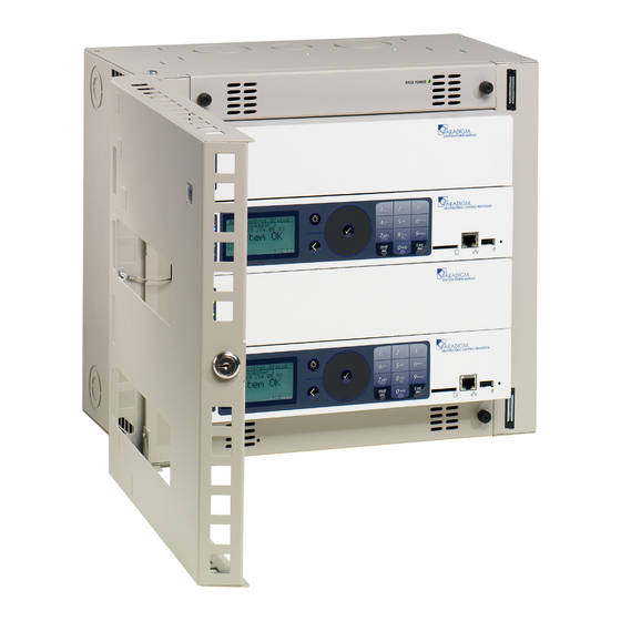
The ERn enclosure is available in two sizes, ERn2 (single processor) and ERn4 (dual processor), The ERn is available in three single phase voltage options, 100-120, 230 CE, and 240 VAC to meet your installation requirements. See the technical datasheet on the ETC website etcconnect.com for a full listing of available models. -
Page 6: Ern Modules And Options
ERn Modules and Options URTO P-ACP P-SPM UBPO P-REP ERn-RPS ERn-NET P-DREP ERn-BM Part Model Description Notes Number P-ACP 7180A1001 Paradigm The P-ACP provides powerful and flexible control for Architectural Control architectural and theatrical applications with integrated Processor networking for both NetConnect and LinkConnect networks. •... - Page 7 Part Model Description Notes Number ERn-NET 7180A1400 ERn Ethernet Switch The ERn-NET module provides four ports of 802.3af Module compliant Power over Ethernet (PoE) and one port for the P- ACP. • Not compatible with a rack-mount ERn enclosure. • Not compatible with ERn4 230 VAC enclosures. UBPO 7180A1411 Unison Battery Pack The UBPO provides back-up power during power outages for...
- Page 8 Warnings and Notice Conventions These symbols are used throughout this installation manual to alert you to danger or important information: Note: Notes are helpful hints and information that is supplemental to the main text. CAUTION: A Caution statement indicates situations where there may be undefined or unwanted consequences of an action, potential for data loss or an equipment problem.
-
Page 9: Contacting Etc
For technical questions about Unison rack systems, contact ETC Technical Services directly at one of the offices listed below. Emergency service is available from all ETC offices outside of normal business hours. When calling for assistance, please have the following information handy: •... -
Page 10: Prepare For Installation
Unpack your order and check the contents against the packing list to be sure your order is complete. If you discover a problem, call ETC Systems Group. Main Circuit Breaker Protection Before you begin installing the Unison external processing rack enclosure, make sure you have installed a main circuit breaker cabinet or other readily accessible input power disconnect device in the same, room or in close proximity to the installed ERn enclosure. -
Page 11: Clearance Requirements
Clearance Requirements Install the ERn enclosure with: • a minimum of 294 mm (15.5 in) front clearance for proper door operation. • a minimum of 152 mm (6 in) clearance from 394 mm the left and right sides from walls or other (15.5”) equipment to allow proper convection airflow in the enclosure. -
Page 12: Wire Requirements
DMX input feed feed to ERn rack ETC Console (for optional stage lighting) power power feed feed The following table lists the recommended control wire types used in a typical Unison installation and the maximum wire runs allowed. -
Page 13: Data Types And Topologies
LinkConnect is topology-free and polarity independent, you can install your LinkConnect data runs in any desired combination of bus, loop, star, and home run. ETC recommends the use of Belden 8471 (or approved equal) wire. The total combined length of a LinkConnect wire run cannot exceed 500 m (1,640 feet) with a maximum distance of 400 m (1,312 feet) between any two devices. -
Page 14: Install Rack Enclosures
Chapter 2 Install Rack Enclosures Install the Rack Enclosure The wall must be strong enough to hold the rack fully populated with modules, conduit and wire. The maximum weight of an ERn enclosure is approximately 20.4 kg (45 lbs). Determine where your rack will be installed using the weight and dimension requirements Where to Install the Enclosure page 6 detailed in... -
Page 15: Rough-In Conduit And Wiring
Rough-in Conduit and Wiring WARNING: RISK OF DEATH BY ELECTRIC SHOCK! Before installing input power, make sure the upstream source of power is off or isolated. Follow appropriate Lockout/Tagout procedures as described in NFPA Standard 70E. AVERTISSEMENT: RISQUE DE MORT PAR ÉLECTROCUTION! Avant d'installer l'alimentation d'entrée, assurez-vous que la source d'alimentation en amont est éteinte ou isolée. -
Page 16: Rough-In Line And Control Conduit And Wiring
Rough-in Line and Control Conduit and Wiring The ERn enclosure requires line power and control wire terminations. For installation convenience all terminations are accessible from the front of the rack. A single phase line power and all required control wires may be pulled through any of the conduit knockouts provided, or other labeled locations. Note: Control (signal) wiring and power wiring must be run in separate conduit in accordance with local code. -
Page 17: Terminate Wiring
Chapter 3 Terminate Wiring Connect Line Power Wiring WARNING: All rack terminations must be done with the power off. Racks installed without an accessible power disconnect device cannot be serviced or operated safely. ERn enclosures are available in 100-120, 230 CE, and 240 VAC single phase configurations. The ERn enclosure requires a single phase, 20 amp (maximum) at 120 VAC input feed or a 15 amp (maximum) at 230 and 240 VAC. -
Page 18: Connect Control Wiring
Connect Control Wiring Note: All low voltage control cables must be run in separate conduit from power wires in accordance with local codes. Low voltage data connects to pluggable connectors on the left and right input/output boards of the ERn enclosure. The ERn2 includes only one each left and right I/O board while the ERn4 includes two of each. -
Page 19: Connect Ern Right I/O Data Terminations
Connect ERn Right I/O Data Terminations 24 VDC In Auxiliary Power - 24 VDC out LinkConnect control DMX A ERn-RPS In Input/Output Ride Thru / Batt DMX Pass-Thru DMX B Input/Output Note: The 24 VDC connection is the power Supply (ERn-PS) connection and is connected for you at the factory. - Page 20 DM X Inpu t Termin a ti on: Sc r e w T e r m i n a l s C o n n e c t o r If daisy-chaining to This graphic illustrates DMX termination layout for the screw- From source another rack or DMX A...
- Page 21 Note: It is required that you terminate LinkConnect and the auxiliary power wiring to the ERn enclosure I/O board that will host the Paradigm Station Power Module. Pull Belden 8471 (or an equal type) control wiring into the ERn enclosure through the conduit opening previously prepared.
-
Page 22: Connect Ern Left I/O Data Terminations
Pull auxiliary control power wiring (typically a red / black wire pair) into the ERn enclosure through the conduit opening previously prepared. Strip 5 mm (3/16 in) of insulation from the ends of each wire pair. Remove the auxiliary power connector from the right I/O board. Loosen the terminal screws for as many auxiliary wire pairs as you are terminating. - Page 23 Connect to Serial RS-232 Integrators and users of advanced systems can interface with the Unison system through the RS-232 connection on the left I/O board. This connection provides an interface with external devices capable of sending or receiving RS-232. This connection can also receive serial commands from a transmitter and provide rack and system status when queried.
- Page 24 T e r m i n a t e C o n t a c t O u t p u ts Remove the contact outputs connector located on the left I/O board. Each connector is labeled for installation convenience. Strip 5 mm (3/16 in) of insulation from the ends of each wire pair.
-
Page 25: Final Installation And Power Up
Chapter 4 Final Installation and Power Up It’s a good idea to look over the entire installation before applying power to the enclosure. WARNING: RISK OF DEATH BY ELECTRIC SHOCK! For your own safety, do not supply power to the enclosure until all installation is complete, connected circuits have been tested and found free of electrical shorts, and covers have been replaced. -
Page 26: Check Line Voltages
Check Line Voltages Check the voltage on your input terminals using a digital volt meter (DVM) before installing modules. WARNING: RISK OF ELECTRIC SHOCK! Working inside the enclosure with power applied exposes you to the possibility of dangerous currents and voltages. Line voltages will be on the input terminals during this procedure. - Page 27 enclosure, or only a Paradigm Station Repeater module (P-REP) in the top module slot with an blank module below. Install either the ERn blank option module, the ERn ethernet switch Module (ERn-NET), or the Redundant Power Supply (ERn-RPS) in the lower option module slot. a: If installing the ERn ethernet switch Module (ERn-NET) or the Redundant Rack Power Supply (ERn-RPS) module in the option module slot, be certain you have completed the installation Install Rack Options...
-
Page 28: Install Rack Options
Chapter 5 Install Rack Options Rack Options Unison ERn options include the RideThru Option (URTO) kit, BatteryPack Option kit (UBPO), Ethernet Switch Module (ERn-NET), and the Redundant Rack Power Supply (ERn-RPS). Additionally you may use a Station Repeater Module in the ERn4 enclosure top module slot instead of Install a Paradigm Repeater or Dual Repeater a secondary Paradigm Station Power Module. - Page 29 Remove modules from the ERn enclosure for RideThru Option board installation access. • For an ERn2, remove only the bottom option module from the rack enclosure. • For an ERn4 with two P-ACPs, remove the bottom option module and the rack power Supply from the rack enclosure.
-
Page 30: Install The Batterypack Option (Ubpo) Kit
Install the BatteryPack Option (UBPO) Kit Note: An ERn enclosure supports the use of either the Unison RideThru Option (URTO) or the Unison BatteryPack Option (UBPO), but not both in the same enclosure. The BatteryPack Option (UBPO) kit provides battery power during power outages to the Paradigm Architectural Control Processor for up to 90 minutes (ERn with a single P-ACP) or up to 45 minutes (ERn4 with two Paradigm ACPs). - Page 31 Install the Unison BatteryPack on to the bottom of the ERn enclosure as pictured below. a: Insert the tabs from the UBPO into the slots in the ERn enclosure. Note: As the BatteryPack is mated to the rack, the connector on the BatteryPack and the connector receptacle installed in step 1a also mate.
-
Page 32: Install A Paradigm Repeater Or Dual Repeater Module
Install a Paradigm Repeater or Dual Repeater Module Both repeater module types may only be utilized in the top module slots of the ERn4 rack enclosure. The Paradigm Station Repeater (P-REP) module extends the system station bus length by 1,640 ft (500 m) and adds support for up to 30 additional stations. - Page 33 Terminate LinkConnect Control Wiring Note: Wire tie down locations provided on rear panel. Unison control stations communicate with the Paradigm Architectural Control Processor using the Echelon LinkPower network (LinkConnect). LinkConnect is based on Echelon LonWorks with LinkPower bidirectional protocol, and uses one pair of wires (data+ and data-). Termination is available for up to twelve home runs of LinkPower data runs utilizing Belden 8471 cable (or approved equal) plus one 14 AWG ESD drain wire when the data cable is not installed in grounded metal conduit.
- Page 34 Replace the connector on the top right I/O board. Terminate Auxiliary Power Auxiliary power is required when you are installing powered Unison control stations. ETC recommends using two 16 AWG (1.5mm ) stranded wires for 24 Vdc auxiliary power to the control station(s).
-
Page 35: Install Redundant Power Supply
Status Indicators When power is applied to the ERn enclosure, the Paradigm Station Repeater Module LEDs located on the front panel illuminate, indicating the status of the auxiliary power, LinkPower control network, and connected stations. The Aux Power and LinkPower LEDs indicate in green when the Paradigm Station Power Module is connected properly and auxiliary power and LinkPower are present. -
Page 36: Install The Ethernet Switch Module
Redundant Power Supply requires servicing. Alternatively, if the primary rack supply status LED is off, but the Redundant Power Supply is on, the primary rack supply requires service. Contact ETC Technical Services for assistance. See Contacting ETC... - Page 37 The Ethernet patch panel includes four punch down terminal blocks that accept CAT5e wire. Building wire enters the ERn enclosure and terminates to this patch panel. For each Ethernet data run, an Ethernet patch cable is provided to connect between the Ethernet patch panel and the Ethernet Switch panel.
- Page 38 Connect CAT5e Wiring Note: All Ethernet terminations must follow IEEE 802.3 and be terminated to the T568B standard. Pull your CAT5e building wire through the conduit access previously prepared. The punch down connector provides insulation displacement therefore stripping of wire is not required.
-
Page 39: Status Indicators
Status Indicators When power is applied to the ERn enclosure, the Paradigm Ethernet Switch Module LEDs, located on the front panel, indicate main power, data, and PoE power status. Power LINK/ACT • The power LED is blue and will illuminate when the Ethernet Switch is powered. •... - Page 40 Holzkirchen, DE +49 (80 24) 47 00-0 Rome, IT +39 (06) 32 111 683 Hong Kong +852 2799 1220 Paris, FR +33 1 4243 3535 etcconnect.com Support support.etcconnect.com Contact etcconnect.com/contactETC © 2020 Electronic Theatre Controls, Inc. Trademark and patent info: etcconnect.com/ip Product information and specifications subject to change. ETC intends this document to be provided in its entirety. 7180M2100 Rev C Released 2020-06...
Need help?
Do you have a question about the Unison ERn2-W and is the answer not in the manual?
Questions and answers