
Related Manuals for ETC Unison AX Series


Summary of Contents for ETC Unison AX Series
- Page 1 Unison Auxiliary Enclosure Series Installation Manual Part Number: 7183M2110 Rev: B Released: 2019-08...
- Page 2 T o v ie w a l i s t o f E T C t r a d e m a r k s a n d p a t e n t s , g o t o etcconnect.com/ip A l l o t h e r t r a d e m a r k s , b o t h m a r k e d a n d no t m a r k e d , a r e t h e p r o p ert y o f t h ei r r es p e c ti v e o w ne r s .
-
Page 3: Table Of Contents
Warnings and Notice Conventions ....1 Help from ETC Technical Services ....2 Unison Auxiliary Enclosure. - Page 4 Final Installation and Power Up ..17 Chapter 5 Check Main Power Wiring ..... .17 Sealing Enclosure Air Leaks .
-
Page 5: Introduction
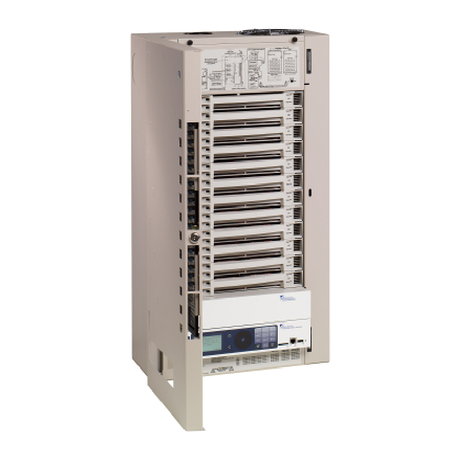
Introduction Welcome to the installation manual for Unison AX series auxiliary enclosures. This manual contains the procedures for safe and efficient installation of an AX main breaker auxiliary enclosure or AX main lug auxiliary enclosure, and the cross-bussed AX12X auxiliary enclosure. -
Page 6: Help From Etc Technical Services
Help from ETC Technical Services If you are having difficulties and your problem is not addressed by this document, try the ETC support website at support.etcconnect.com or the main ETC website at etcconnect.com. If none of these resources are sufficient, contact ETC Technical Services directly at one of the offices identified below. -
Page 7: Unison Auxiliary Enclosure
DRd configuration. AX Series Enclosure Options Unison AX series enclosures are designed to provide main lug or main circuit breaker input feed provisions for single DRd6 or DRd12 applications. • AX6-MCB-1-150 – includes main breaker for DRd6, 150 A/1Ø, 3-wire •... -
Page 8: Prepare For Installation
Before you begin installing the Unison auxiliary enclosure, make sure you have installed a main circuit breaker cabinet or other readily accessible input power disconnect device. In certain bussed and cross- bussed systems, this disconnect device may be the Unison AX series auxiliary enclosure with a main circuit breaker. -
Page 9: Maximum Current Draw Of Enclosures
Maximum Current Draw of Enclosures 120/277 V 240 V Maximum Enclosure Phase Type Maximum Current Type Current Draw Draw Single-phase (1Ø) 120 A – Three-phase (3Ø) 80 A 60 A Single-phase (1Ø) 240 A – AX12 Three-phase (3Ø) 160 A 120 A Single-phase (1Ø) 480 A... -
Page 10: Where To Install The Enclosure
Where to Install the Enclosure Unison auxiliary enclosures are designed to be surface mounted on load bearing walls in an electrical closet or a room with restricted public access. It is recommended that you install the enclosure at least 914.4 mm (36 in) off the floor surface. Clearance Requirements Unison DRd enclosures require 305 mm (12 in) top clearance for proper airflow through the cabinet. -
Page 11: Installation Environment Requirements
• Soundproofing or performance area separation to muffle ventilation fan noise. Wire Routing and Specification Unison AX series enclosures have conduit knockouts on both sides of the cabinet for feed through to the adjacent DRd enclosure(s). The top and bottom are intentionally left blank to allow holes to be punched to match the incoming conduit. - Page 12 AX and AX12X Auxiliary Enclosure It is required that line feed enters from the top or bottom panels of the enclosure. The side knockouts are provided for cross-bussing and data interconnect feed through to the adjacent DRd dimming enclosure(s). The corresponding number of chase nipples with integral bushings are included. Wire Wire Access Interconnect wiring to...
-
Page 13: Install Enclosures
Chapter 2 Install Enclosures Mounting Auxiliary and DRd Enclosures Together One DRd may be bussed to the AX series auxiliary enclosure, which contains a main circuit breaker (MCB) for power distribution to the adjacent DRd enclosure. Two DRd12 enclosures may be cross-bussed to an AX12X which is designed to provide main lug or main breaker input feed termination to the adjacent DRd12 enclosures. - Page 14 Remove the knockouts from the side conduit plug on the DRd and auxiliary enclosure before installation. Only remove the knockouts that are adjacent to another enclosure. Install the DRd first, following the instructions as outlined in the DRd Enclosure Installation Manual.
-
Page 15: Rough-In Conduit And Wiring
Chapter 3 Rough-in Conduit and Wiring Wire Routing and Specification page 7 . Line or (input feed) wires for standard AX series enclosures should enter through the top or bottom. All terminations are accessible from the front of the enclosure. DRd enclosure with AX enclosure Two DRd12 enclosures with AX12X enclosure Rough-in Conduit and Wiring... -
Page 16: Rough-In Line Conduit To The Auxiliary Enclosure
Remove the side conduit knockout from adjoining side of the auxiliary enclosure and the DRd enclosure. When installing in a cross-bussed application, remove both side knockouts. Install the ETC supplied nylon insulated chase nipple to the knockouts between the auxiliary and DRd enclosure(s). -
Page 17: Connect Line Power
Follow all local codes and restrictions. CAUTION: Load wires used with ETC dimming systems must be copper. Do not use wire containing aluminum. Line wires for the AX enclosures can be aluminum or copper. - Page 18 Main Lug Main Circuit Breaker Phase lugs Neutral lugs Neutral lugs Ground lugs Phase lugs Ground lugs Pull the line phase, neutral, and ground cables to the enclosure through the conduit openings previously prepared. Strip one inch of insulation from the end of each cable and terminate them to the lugs. Line connections are labeled L1, L2, L3 (for three-phase) and N.
- Page 19 Lug Wire Hex Key AX Enclosure Wire Lug Wire Range Wire Size for Torque Torque Size 17 Nm Single 25 to 35 mm (150 in-lb) (3 to 1 AWG ) Single 10 to 150 mm Phase 5/16” (8 AWG to 350 kcmil) 31 Nm 50 to 185 mm (275 in-lb)
-
Page 20: Route And Connect Interconnect Cables To Adjacent
Route and Connect Interconnect Cables to Adjacent DRd Enclosure(s) ETC has supplied extra-flexible wire for phase, neutral, and ground lugs from the auxiliary enclosure to the DRd enclosure(s). Once your auxiliary and DRd enclosures are installed, feed the load wires through the side chase nipples to the adjacent DRd enclosure phase, neutral, and ground lugs. -
Page 21: Chapter 5 Final Installation And Power Up
Chapter 5 Final Installation and Power Up It’s a good idea to look over the entire installation before applying power to the system. WARNING: RISK OF ELECTRIC SHOCK! Auxiliary enclosures installed without an accessible power disconnect device cannot be serviced or operated safely. Follow all local codes and restrictions. -
Page 22: Appendix A Dual Drd12 With Cross-Bussed Acp
Data Interconnect Cable AX12X enclosures ship with a data interconnect cable, ETC part 7183B7003. The ends of the interconnect cable install to the Right I/O board in each DRd enclosure. The ends of the interconnect cable are labeled "Rack 1" and "Rack 2" to indicate where each end of the cable should be installed. -
Page 23: Installation Procedure
Installation Procedure WARNING: RISK OF ELECTRIC SHOCK! Failure to disconnect all power to the panel before working inside could result in serious injury or death. De-energize main feed to the dimmer rack and follow appropriate Lockout/ Tagout procedures as mandated by NFPA 70E. It is important to note that electrical equipment such as dimmer racks can present an arc flash hazard if improperly serviced. - Page 24 Holzkirchen, DE +49 (80 24) 47 00-0 Rome, IT +39 (06) 32 111 683 Hong Kong +852 2799 1220 Paris, FR +33 1 4243 3535 etcconnect.com Support support.etcconnect.com Contact etcconnect.com/contactETC © 2019 Electronic Theatre Controls, Inc. Trademark and patent info: etcconnect.com/ip Product information and specifications subject to change. ETC intends this document to be provided in its entirety. 7183M2110 Rev B Released 2019-08...
Need help?
Do you have a question about the Unison AX Series and is the answer not in the manual?
Questions and answers