Table of Contents
Advertisement
Quick Links
Advertisement
Table of Contents

Related Manuals for Planet FGSW-2840


Summary of Contents for Planet FGSW-2840
- Page 2 PLANET is a registered trademark of PLANET Technology Corp. All other trademarks belong to their respective owners. Disclaimer PLANET Technology does not warrant that the hardware will work properly in all environments and applications, and makes no warranty and representation, either implied or expressed, with respect to the quality, performance, merchantability, or fitness for a particular purpose.
-
Page 3: Table Of Contents
User’s Manual of FGSW-2840 / FGSW-4840S TABLE OF CONTENTS 1. INTRODUCTION........................9 1.1 Package Contents ............................9 1.2 Product Description ...........................10 1.3 How to Use This Manual ..........................11 1.4 Product Features............................12 1.5 Product Specifications ..........................14 2. INSTALLATION ........................17 2.1 Hardware Description ..........................17 2.1.1 Switch Front Panel ..............................17... - Page 4 User’s Manual of FGSW-2840 / FGSW-4840S 4.2.2.2 User Config ...............................42 4.2.3 System Tools ...............................44 4.2.3.1 Config Restore ............................45 4.2.3.2 Config Backup ............................46 4.2.3.3 Firmware Upgrade.............................47 4.2.3.4 System Reboot ............................48 4.2.3.5 System Reset ............................49 4.2.4 Access Security ..............................50 4.2.4.1 Access Control ............................51 4.2.4.2 SSL Config ..............................53...
- Page 5 User’s Manual of FGSW-2840 / FGSW-4840S 4.5.3 MSTP Instance ..............................127 4.5.3.1 Region Config............................128 4.5.3.2 Instance Config............................129 4.5.3.3 Instance Port Config ..........................131 4.5.4 STP Security..............................133 4.5.4.1 Port Protect .............................134 4.5.4.2 TC Protect ...............................136 4.6 Multicast ..............................137 4.6.1 IGMP Snooping ..............................140 4.6.1.1 Snooping Config ............................142 4.6.1.2 Port Config ..............................143...
- Page 6 User’s Manual of FGSW-2840 / FGSW-4840S 4.8.1.4 Standard-IP ACL............................186 4.8.1.5 Extend-IP ACL ............................187 4.8.2 Policy Config..............................188 4.8.2.1 Policy Summary............................189 4.8.2.2 Policy Create ............................190 4.8.2.3 Action Create ............................191 4.8.3 Policy Binding ..............................192 4.8.3.1 Binding Table ............................193 4.8.3.2 Port Binding .............................194 4.8.3.3 VLAN Binding ............................195 4.9 SNMP .................................196...
- Page 7 User’s Manual of FGSW-2840 / FGSW-4840S 4.12 Logout ..............................235 5. COMMAND LINE INTERFACE..................236 5.1 Accessing the CLI ............................236 5.2 Telnet Login ..............................236 6. COMMAND LINE MODE ....................237 6.1 User EXEC Mode Commands........................239 6.1.1 broadcast command ............................239 6.1.2 enable command ...............................239 6.1.3 logout command ..............................240...
- Page 8 User’s Manual of FGSW-2840 / FGSW-4840S 6.3.7 lacp Command ..............................247 6.3.8 location Command.............................247 6.3.9 logging Command .............................247 6.3.10 loopback-detection Command .........................248 6.3.11 mac Command..............................248 6.3.12 monitor Command ............................248 6.3.13 port-channel Command ...........................249 6.3.14 qos Command ..............................249 6.3.15 rmon Command ...............................249 6.3.16 snmp-server Command ...........................250...
-
Page 9: Introduction
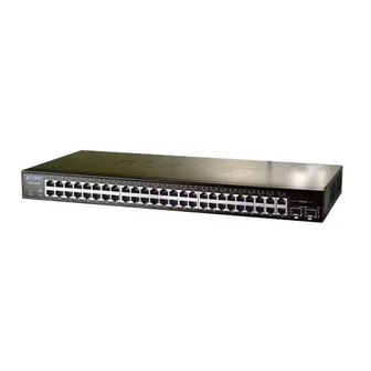
User’s Manual of FGSW-2840 / FGSW-4840S 1. INTRODUCTION Thank you for purchasing PLANET 24 / 48-Port 10/100TX + 4-Port Gigabit Managed Switch, FGSW-2840/FGSW-4840S. The descriptions of these two models are shown below: 24-Port 10/100TX + 4-Port Gigabit with 2 Combo 100/1000X SFP Managed Switch... -
Page 10: Product Description
(FGSW-4840S). Its four built-in GbE uplink ports also offer incredible extensibility, flexibility and connectivity to the core switch or servers. The powerful features of QoS and network security offered by the FGSW-2840 / FGSW-4840S enable the switch to perform effective data traffic control for ISP and enterprise VoIP, video streaming and multicast applications. It is ideal for the remote access layer of campus or enterprise networks and the aggregation layer of IP metropolitan networks. -
Page 11: How To Use This Manual
Flexible Extension Solution The two mini-GBIC slots built in the FGSW-2840 / FGSW-4840S are compatible with the 1000Base-SX/LX SFP (Small Form-factor Pluggable) fiber transceiver to uplink to the backbone switch and monitoring center in long distance. The distance can be extended from 550 meters (multi-mode fiber) to 10/20/30/40/50/60/70/120 kilometers (single-mode fiber or WDM fiber). -
Page 12: Product Features
User’s Manual of FGSW-2840 / FGSW-4840S 1.4 Product Features Physical Port (FGSW-2840) ■ 24-port 10/100Base-TX Fast Ethernet RJ45 copper, auto MDI / MDIX ■ 4-port 10/100/1000Base-T Gigabit Ethernet RJ45 copper, auto MDI / MDIX ■ 2 Combo 100/1000Base-X mini-GBIC/SFP slots (Share with Port 27/28) ■... - Page 13 User’s Manual of FGSW-2840 / FGSW-4840S Multicast ■ IGMP Snooping v1, v2 and v3 ■ Multicast IP Table / Static Multicast IP ■ Multicast Filter Security ■ L2 / L3 / L4 Access Control List ■ MAC Security Static MAC ...
-
Page 14: Product Specifications
User’s Manual of FGSW-2840 / FGSW-4840S 1.5 Product Specifications Product FGSW-2840 FGSW-4840S Hardware Specifications Hardware Version 10/100TX Copper Ports (MDI/MDIX) 10/100/1000T Copper Ports (MDI/MDIX) 2 100/1000Base-X SFP interfaces 2 1000Base-X SFP interfaces SFP/mini-GBIC Slots 12.8Gbps / non-blocking 17.6Gbps / non-blocking Switch Fabric 9.5Mpps @64 bytes... - Page 15 User’s Manual of FGSW-2840 / FGSW-4840S IEEE 802.3ad LACP and static trunk supports 6 groups of 4-port trunk. Link Aggregation 802.1Q tagged-based VLAN, up to 512 VLAN groups, out of 4094 VLAN IDs VLAN Management VLAN IEEE 802.1D STP IEEE 802.1w RSTP Spanning Tree Protocol IEEE 802.1s MSTP...
- Page 16 User’s Manual of FGSW-2840 / FGSW-4840S FCC Part 15 Class A, CE Regulation Compliance IEEE 802.3 10Base-T IEEE 802.3u 100Base-TX / 100Base-FX IEEE 802.3z Gigabit SX/LX IEEE 802.3ab Gigabit 1000Base-T IEEE 802.3x Flow Control and Back pressure IEEE 802.3ad Port Trunk with LACP IEEE 802.1D Spanning Tree protocol...
-
Page 17: Installation
User’s Manual of FGSW-2840 / FGSW-4840S 2. INSTALLATION This section describes the hardware features and installation of the Managed Switch on the desktop or rack mount. For easier management and control of the Managed Switch, familiarize yourself with its display indicators, and ports. Front panel illustrations in this chapter display the unit LED indicators. -
Page 18: Led Indications
User’s Manual of FGSW-2840 / FGSW-4840S ■ Reset Button At front panel of Managed Switch, the reset button is designed for reboot the Managed Switch without turn off and on the power. The following is the summary table of Reset button... - Page 19 User’s Manual of FGSW-2840 / FGSW-4840S ■ 10/100/1000Base-T Interfaces (Port 25 to port 28) Color Function Lights: To indicate the link through that port is successfully established at 1000Mbps. 1000 Green LNK/ACT Blink: To indicate that the Switch is actively sending or receiving data over that port.
-
Page 20: Switch Rear Panel
User’s Manual of FGSW-2840 / FGSW-4840S ■ 10/100/1000Base-T Interfaces (Port 49 to port 50) Color Function Lights: To indicate the link through that port is successfully established at 1000Mbps. 1000 Green LNK/ACT Blink: To indicate that the Switch is actively sending or receiving data over that port. -
Page 21: Installing The Switch
User’s Manual of FGSW-2840 / FGSW-4840S In some areas, installing a surge suppression device may also help to protect your Managed Switch Power Notice: from being damaged by unregulated surge or current to the Managed Switch or the power adapter. -
Page 22: Rack Mounting
User’s Manual of FGSW-2840 / FGSW-4840S Supply power to the Managed Switch. Step5: Connect one end of the power cable to the Managed Switch. Connect the power plug of the power cable to a standard wall outlet. When the Managed Switch receives power, the Power LED should remain solid Green. -
Page 23: Installing The Sfp Transceiver
User’s Manual of FGSW-2840 / FGSW-4840S Figure 2-1-9: Mounting Managed Switch in a Rack Proceeds with Steps 4 and 5 of session 2.2.1 Desktop Installation to connect the network cabling and supply power to Step6: the Managed Switch. 2.2.3 Installing the SFP transceiver The sections describe how to insert an SFP transceiver into an SFP slot. - Page 24 User’s Manual of FGSW-2840 / FGSW-4840S Approved PLANET SFP Transceivers PLANET Managed Switch supports both Single mode and Multi-mode SFP transceiver. The following list of approved PLANET SFP transceivers is correct at the time of publication: Gigabit SFP Transceiver Modules (FGSW-2840 / FGSW-4840S) ...
- Page 25 User’s Manual of FGSW-2840 / FGSW-4840S duplex LC connector type. Connect the Fiber Cable Insert the duplex LC connector into the SFP transceiver. Connect the other end of the cable to a device with SFP transceiver installed. Check the LNK/ACT LED of the SFP slot on the front of the Managed Switch. Ensure that the SFP transceiver is operating correctly.
-
Page 26: Switch Management
User’s Manual of FGSW-2840 / FGSW-4840S 3. SWITCH MANAGEMENT This chapter explains the methods that you can use to configure management access to the Managed Switch. It describes the types of management applications and the communication and management protocols that deliver data between your management device (workstation or personal computer) and the system. -
Page 27: Management Access Overview
User’s Manual of FGSW-2840 / FGSW-4840S 3.2 Management Access Overview The Managed Switch gives you the flexibility to access and manage it using any or all of the following methods: Web browser interface An external SNMP-based network management application The administration Web browser interface supports are embedded in the Managed Switch software and are available for immediate use. -
Page 28: Snmp-Based Network Management
User’s Manual of FGSW-2840 / FGSW-4840S The following web screen based on FGSW-4840S, for FGSW-2840 the display will be the same to FGSW-4840S. Figure 3-2: Web Main Screen of Managed Switch 3.4 SNMP-Based Network Management You can use an external SNMP-based application to configure and manage the Managed Switch, such as SNMPc Network Manager, HP Openview Network Node Management (NNM) or What’s Up Gold. -
Page 29: Web Configuration
By default, IE8.0 or later version does not allow Java Applets to open sockets. The user has to explicitly modify the browser setting to enable Java Applets to use network ports. The following web screen based on FGSW-4840S, for FGSW-2840 the display will be the same to FGSW-4840S. - Page 30 User’s Manual of FGSW-2840 / FGSW-4840S http://192.168.0.100 When the following login screen appears, please enter the default username "admin" with password “admin” to login the main screen of Managed Switch. The login screen in Figure 4-1-2 appears. Figure 4-1-2: Login Screen...
- Page 31 User’s Manual of FGSW-2840 / FGSW-4840S Now, you can use the Web management interface to continue the switch management or manage the Managed Switch by Web interface. The Switch Menu on the left of the web page let you access all the commands and statistics the Managed Switch provides.
-
Page 32: Main Web Page
User’s Manual of FGSW-2840 / FGSW-4840S 4.1 Main Web Page The Managed Switch provides a Web-based browser interface for configuring and managing it. This interface allows you to access the Managed Switch using the Web browser of your choice. This chapter describes how to use the Managed Switch’s Web browser interface to configure and manage it. - Page 33 User’s Manual of FGSW-2840 / FGSW-4840S Main Menu Using the onboard web agent, you can define system parameters, manage and control the Managed Switch and all its ports, or monitor network conditions. Via the Web-Management, the administrator can set up the Managed Switch by selecting the functions listed in the Main Function.
-
Page 34: System
User’s Manual of FGSW-2840 / FGSW-4840S 4.2 System Use the System menu items to display and configure basic administrative details of the Managed Switch. Under System, the following topics are provided to configure and view the system information. This section has the following items: The switch system information is provided here. -
Page 35: System Summary
User’s Manual of FGSW-2840 / FGSW-4840S 4.2.1.1 System Summary The port status diagram shows the working status of 10/100Mbps RJ45 ports, 10/100/1000Mbps RJ45 ports and 2 SFP ports of the Managed Switch, the System Summary includes the Managed Switch system information and the screen in Figure 4-2-2 appears. -
Page 36: Device Description
User’s Manual of FGSW-2840 / FGSW-4840S 4.2.1.2 Device Description This page allows configuring the description of the Managed Switch, including device name, device location and system contact. After setup is completed, please press “Apply” button to take effect, and the screen in Figure 4-2-3 appears. -
Page 37: System Time
User’s Manual of FGSW-2840 / FGSW-4840S 4.2.1.3 System Time This page allows configuring system time and the settings here will be used for other time-based functions. After setup is completed, please press “Apply” button to take effect, and the screen in Figure 4-2-4 appears. -
Page 38: Daylight Saving Time
User’s Manual of FGSW-2840 / FGSW-4840S The system time will be restored to the default when the Managed Switch is restarted and you need to reconfigure the system of the Managed Switch. When Get Time from NTP Server is selected and no time server is configured, the Managed Switch will get time from the time server of the Internet if it has connected to the Internet. -
Page 39: System Ip
User’s Manual of FGSW-2840 / FGSW-4840S Europe: Last Sunday in March, 01:00 ~ Last Sunday in October, 01:00. New Zealand: Last Sunday in September, 02:00 ~ First Sunday in April, 03:00. Recurring Mode Specify the DST configuration in recurring mode. This configuration is recurring in use. - Page 40 User’s Manual of FGSW-2840 / FGSW-4840S The page includes the following fields: Object Description MAC Address Displays MAC Address of the Managed Switch. IP Address Mode Select the mode to obtain IP Address for the Managed Switch. Static IP: When this option is selected, you should enter IP Address, Subnet Mask and ...
-
Page 41: User Management
User’s Manual of FGSW-2840 / FGSW-4840S 4.2.2 User Management The User Management functions to configure the user name and password for users to log on to the Web management page with a certain access level so as to protect the settings of the Managed Switch from being randomly changed; the screen in Figure 4-2-7 appears. -
Page 42: User Table
User’s Manual of FGSW-2840 / FGSW-4840S 4.2.2.1 User Table This page provides view the information about the current users of the Managed Switch; the screen in Figure 4-2-8 appears. Figure 4-2-8: User Table Page Screenshot 4.2.2.2 User Config This page allows configuring the access level of the user to log on to the Web management page of Managed Switch.The Managed Switch provides two access levels: Guest and Admin. - Page 43 User’s Manual of FGSW-2840 / FGSW-4840S The page includes the following fields: Object Description User Information User Name Create a name for users’ login. Access Level Select the access level to login. Admin: allow edit, modify and view all the settings of different functions.
-
Page 44: System Tools
User’s Manual of FGSW-2840 / FGSW-4840S 4.2.3 System Tools The System Tools function, allowing to manage the configuration file of the Managed Switch, can be implemented on the Config Restore, Config Backup, Firmware Upgrade, System Reboot and System Reset pages; the screen in Figure 4-2-10 appears. -
Page 45: Config Restore
User’s Manual of FGSW-2840 / FGSW-4840S 4.2.3.1 Config Restore This page provides uploading a backup configuration file to restore Managed Switch to the previous configuration; the screen in Figure 4-2-11 appears. Figure 4-2-11: Config Restore Page Screenshot The page includes the following fields:... -
Page 46: Config Backup
User’s Manual of FGSW-2840 / FGSW-4840S 4.2.3.2 Config Backup This page provides downloading the current configuration and saving it as a file to your computer for future configuration restore; the screen in Figure 4-2-12 appears. Figure 4-2-12: Config Backup Page Screenshot... -
Page 47: Firmware Upgrade
User’s Manual of FGSW-2840 / FGSW-4840S 4.2.3.3 Firmware Upgrade This page provides firmware upgrade function of Managed Switch; the screen in Figure 4-2-13 appears. Figure 4-2-13: Firmware Upgrade Page Screenshot The page includes the following fields: Object Description Upgrade Click the Upgrade button to start firmware upgrade process. -
Page 48: System Reboot
User’s Manual of FGSW-2840 / FGSW-4840S 4.2.3.4 System Reboot This page provides system reboot function of Managed Switch; the screen in Figure 4-2-14 appears. Figure 4-2-14: System Reboot Page Screenshot The page includes the following fields: Object Description Save Config Choose to save the current config of Managed Switch. -
Page 49: System Reset
User’s Manual of FGSW-2840 / FGSW-4840S 4.2.3.5 System Reset This page provide resetting the Managed Switch to the default and all the settings will be cleared after the Managed Switch is reset; the screen in Figure 4-2-15 appears. Figure 4-2-15: System Reset Page Screenshot... -
Page 50: Access Security
User’s Manual of FGSW-2840 / FGSW-4840S 4.2.4 Access Security Access Security provides different security measures for the remote login so as to enhance the configuration management security. It can be implemented on the Access Control, SSL Config and SSH Config pages; the screen in Figure 4-2-16 appears. -
Page 51: Access Control
User’s Manual of FGSW-2840 / FGSW-4840S 4.2.4.1 Access Control This page provides controlling the users logging on to the Web management page to enhance the configuration management security. The definitions of Admin and Guest can be referred to Chapter 4.2.2 under User Management; the screen in... - Page 52 User’s Manual of FGSW-2840 / FGSW-4840S IP Address & MASK These fields can be available for configuration only when IP-based mode is selected. Only the users within the IP-range you set here are allowed for login. MAC Address The field can be available for configuration only when MAC-based mode is selected.
-
Page 53: Ssl Config
User’s Manual of FGSW-2840 / FGSW-4840S 4.2.4.2 SSL Config SSL (Secure Sockets Layer), a security protocol, is to provide a secure connection for the application layer protocol (e.g. HTTP) communication based on TCP. SSL is widely used to secure the data transmission between the Web browser and servers. It is mainly applied through ecommerce and online banking. - Page 54 User’s Manual of FGSW-2840 / FGSW-4840S The page includes the following fields: Object Description Global Config SSL Select Enable/Disable the SSL function on the Managed Switch. Certification Download Certification File Select the desired certificate to download to the Managed Switch. The certificate must be BASE64 encoded.
-
Page 55: Ssh Config
User’s Manual of FGSW-2840 / FGSW-4840S 4.2.4.3 SSH Config As stipulated by IFTF (Internet Engineering Task Force), SSH (Secure Shell) is a security protocol established on application and transport layers. SSH-encrypted-connection is similar to a Telnet connection, but essentially the old Telnet remote management method is not safe, because the password and data transmitted with plain text can be easily intercepted. - Page 56 User’s Manual of FGSW-2840 / FGSW-4840S The page includes the following fields: Object Description Global Config SSH Select Enable/Disable the SSH function on the Managed Switch. Select Enable/Disable SSH V1 to be the supported protocol. Protocol V1 Protocol V2 Select Enable/Disable SSH V2 to be the supported protocol.
- Page 57 User’s Manual of FGSW-2840 / FGSW-4840S Application Example 1 for SSH: Network Requirements Log on to the Managed Switch via password authentication using SSH and the SSH function is enabled on the Managed Switch. PuTTY client software is recommended.
- Page 58 User’s Manual of FGSW-2840 / FGSW-4840S Application Example 2 for SSH: Network Requirements Log on to the Managed Switch via key authentication using SSH and the SSH function is enabled on the Managed Switch. PuTTY client software is recommended.
- Page 59 User’s Manual of FGSW-2840 / FGSW-4840S On the Web management page of the Managed Switch, download the public key file saved in the computer to the Managed Switch. The key type should accord with the type of the key file.
- Page 60 User’s Manual of FGSW-2840 / FGSW-4840S Click Browse to download the private key file to SSH client software and click Open. After successful authentication, please enter the login user name. If you log on to the Managed Switch without entering...
-
Page 61: Switching
User’s Manual of FGSW-2840 / FGSW-4840S 4.3 Switching Use the System menu items to display and configure basic administrative details of the Managed Switch. Under System the following topics are provided to configure and view the system information: The Switching function is used to configure the basic functions of the Managed Switch; the screen in Figure 4-3-1 appears. -
Page 62: Port
User’s Manual of FGSW-2840 / FGSW-4840S 4.3.1 Port The Port function, allowing you to configure the basic features for the port, is implemented on the Port Config, Port Mirror, Port Security, Port Isolation and Loopback Detection pages. The screen in Figure 4-3-2 appears. -
Page 63: Port Config
User’s Manual of FGSW-2840 / FGSW-4840S 4.3.1.1 Port Config This page provides configuring the basic parameters for the ports of Managed Switch. When the port is disabled, the packets on the port will be discarded. Disabling the port which is vacant for a long time can reduce the power consumption effectively and it can enable the port when it is in need;... - Page 64 When using the SFP port with a 100M module or a gigabit module, it needs to configure its corresponding Speed and Duplex mode. For 100M module, please select 100MFD while selecting 1000MFD for gigabit module. By default, the Speed and Duplex mode of SFP port is 1000MFD. (For FGSW-2840 only)
-
Page 65: Port Mirror
User’s Manual of FGSW-2840 / FGSW-4840S 4.3.1.2 Port Mirror Port Mirror, the packets obtaining technology, functions to forward copies of packets from one/multiple ports (mirrored port) to a specific port (mirroring port). Usually, the mirroring port is connected to a data diagnose device, which is used to analyze the mirrored packets for monitoring and troubleshooting the network. - Page 66 User’s Manual of FGSW-2840 / FGSW-4840S Click Edit and the following screen appears. Figure 4-3-5: Port Mirror Edit Page Screenshot The page includes the following fields: Object Description Mirror Group Group Select the mirror group number that wants to configure.
- Page 67 User’s Manual of FGSW-2840 / FGSW-4840S number you entered. Select Select the desired port as a mirrored port. It is multi-optional. Port Displays the port number. Ingress Select Enable/Disable the Ingress feature. When the Ingress is enabled, the incoming packets received by the mirrored port will be copied to the mirroring port.
-
Page 68: Port Security
User’s Manual of FGSW-2840 / FGSW-4840S 4.3.1.3 Port Security MAC Address Table maintains the mapping relationship between the port and the MAC address of the connected device, which is the base of the packet forwarding. The capacity of MAC Address Table is fixed. MAC Address Attack is the attack method that the attacker takes to obtain the network information illegally. - Page 69 User’s Manual of FGSW-2840 / FGSW-4840S Select the desired port for Port Security configuration. It is multi-optional. Select Port Displays the port number. Max Learned MAC Specify the maximum number of MAC addresses that can be learned on the port.
-
Page 70: Port Isolation
User’s Manual of FGSW-2840 / FGSW-4840S 4.3.1.4 Port Isolation Port Isolation provides a method of restricting traffic flow to improve the network security by forbidding the port to forward packets to the ports that are not on its forward port list; the screen in Figure 4-3-7 appears. - Page 71 User’s Manual of FGSW-2840 / FGSW-4840S Forward Port list Select the port that to be forwarded to. Port Isolation List Port Display the port number. Forward Port list Display the forward list. Buttons : Click to select whole ports.
-
Page 72: Loopback Detection
User’s Manual of FGSW-2840 / FGSW-4840S 4.3.1.5 Loopback Detection With loopback detection feature enabled, the Managed Switch can detect loops using loopback detection packets. When a loop is detected, the Managed Switch will display an alert or further block the corresponding port according to the port configuration;... - Page 73 User’s Manual of FGSW-2840 / FGSW-4840S Status Detection Interval Set a loopback detection interval between 1 and 1000 seconds. By default, it’s 30 seconds. Automatic Recovery Time allowed for automatic recovery when a loopback is detected. It can be set as Time integral multiple of detection interval.
-
Page 74: Lag
User’s Manual of FGSW-2840 / FGSW-4840S 4.3.2 LAG LAG (Link Aggregation Group) is to combine a number of ports together to make a single high-bandwidth data path, so as to implement the traffic load sharing among the member ports in the group and to enhance the connection reliability. -
Page 75: Lag Table
User’s Manual of FGSW-2840 / FGSW-4840S 4.3.2.1 LAG Table This page provides view the information of the current LAG of Managed Switch; the screen in Figure 4-3-10 appears. Figure 4-3-10: LAG Table Page Screenshot The page includes the following fields:... - Page 76 User’s Manual of FGSW-2840 / FGSW-4840S Buttons : Click to apply changes. : Click to select whole ports. : Click to delete current LAG group. : Click to display help web page.
-
Page 77: Static Lag
User’s Manual of FGSW-2840 / FGSW-4840S 4.3.2.2 Static LAG This page provides manually configuring the LAG of Managed Switch; the screen in Figure 4-3-11 appears. Figure 4-3-11: Static LAG Page Screenshot The page includes the following fields: Object Description LAG Config ... -
Page 78: Lacp Config
User’s Manual of FGSW-2840 / FGSW-4840S The traffic load of the LAG will be balanced among the ports according to the Aggregate Arithmetic. If the connections of one or several ports are broken, the traffic of these ports will be transmitted on the normal ports, so as to guarantee the connection reliability. - Page 79 User’s Manual of FGSW-2840 / FGSW-4840S Figure 4-3-12: LACP Config Page Screenshot The page includes the following fields: Object Description Global Config System Priority Specify the system priority for the Managed Switch. The system priority and MAC address constitute the system identification (ID). A lower system priority value indicates a higher system priority.
- Page 80 User’s Manual of FGSW-2840 / FGSW-4840S Select Select the desired port for LACP configuration. It is multi-optional. Port Displays the port number. Admin Key Specify an admin key for the port. The member ports in a dynamic aggregation group must have the same admin key.
-
Page 81: Traffic Monitor
User’s Manual of FGSW-2840 / FGSW-4840S 4.3.3 Traffic Monitor The Traffic Monitor function, monitoring the traffic of each port, is implemented on the Traffic Summary and Traffic Statistics pages. The screen in Figure 4-3-13 appears. Figure 4-3-13: Traffic Monitor Page Screenshot... -
Page 82: Traffic Summary
User’s Manual of FGSW-2840 / FGSW-4840S 4.3.3.1 Traffic Summary This page provides displaying the traffic information of each port, which facilitates to monitor the traffic and analyze the network abnormity; the screen in Figure 4-3-14 appears. Figure 4-3-14: Traffic Summary Page Screenshot... -
Page 83: Traffic Statistics
User’s Manual of FGSW-2840 / FGSW-4840S counted in. Packets Tx Displays the number of packets transmitted on the port. Octets Rx Displays the number of octets received on the port. The error octets are counted in. Displays the number of octets transmitted on the port. - Page 84 User’s Manual of FGSW-2840 / FGSW-4840S Refresh Rate Enter a value in seconds to specify the refresh interval. Statistics Port Select Enter a port number and click the Select button to view the traffic statistics of the corresponding port.
-
Page 85: Mac Address
User’s Manual of FGSW-2840 / FGSW-4840S 4.3.4 MAC Address The main function of the Managed Switch is forwarding the packets to the correct ports based on the destination MAC address of the packets. Address Table contains the port-based MAC address information, which is the base for the Managed Switch to forward packets quickly. -
Page 86: Address Table
User’s Manual of FGSW-2840 / FGSW-4840S The page includes the following fields: Object Description Address Table Allow to view all the information of the Address Table. The static address table maintains the static address entries which can be added ... - Page 87 User’s Manual of FGSW-2840 / FGSW-4840S Type Select the type of your desired entry. All: This option allows the address table to display all the address entries. Static: This option allows the address table to display the static address ...
-
Page 88: Static Address
User’s Manual of FGSW-2840 / FGSW-4840S 4.3.4.2 Static Address The static address table maintains the static address entries which can be added or removed manually, independent of the aging time. In the stable networks, the static MAC address entries can facilitate the Managed Switch to reduce broadcast packets and remarkably enhance the efficiency of packets forwarding without learning the address. - Page 89 User’s Manual of FGSW-2840 / FGSW-4840S MAC: Enter the MAC address of your desired entry. VLAN ID: Enter the VLAN ID number of your desired entry. Port: Enter the Port number of your desired entry. Static Address Table ...
-
Page 90: Dynamic Address
User’s Manual of FGSW-2840 / FGSW-4840S 4.3.4.3 Dynamic Address The dynamic address can be generated by the auto-learning mechanism of the Managed Switch. The Dynamic Address Table can update automatically by auto-learning or aging out the MAC address. To fully utilize the MAC address table, which has a limited capacity, the Managed Switch adopts an aging mechanism for updating the table. - Page 91 User’s Manual of FGSW-2840 / FGSW-4840S Port: Enter the Port number of desired entry. LAG ID:Enter the LAG ID of desired entry. Dymanic Address Table Select Select the entry to delete the dynamic address or to bind the MAC address to the corresponding port statically.
-
Page 92: Filtering Address
User’s Manual of FGSW-2840 / FGSW-4840S 4.3.4.4 Filtering Address The filtering address is to forbid the undesired packets to be forwarded; the filtering address can be added or removed manually, independent of the aging time. The filtering MAC address allows the Managed Switch to filter the packets which includes this MAC address as the source address or destination address, so as to guarantee the network security. - Page 93 User’s Manual of FGSW-2840 / FGSW-4840S MAC Address Displays the filtering MAC Address. Displays the corresponding VLAN ID. VLAN ID Port Here the symbol “__” indicates no specified port. Displays the Type of the MAC address. Type ...
-
Page 94: Dhcp Filtering
User’s Manual of FGSW-2840 / FGSW-4840S 4.3.5 DHCP Filtering Nowadays, the network is getting larger and more complicated. The amount of the PCs always exceeds that of the assigned IP addresses. The wireless network and the laptops are widely used and the locations of the PCs are always changed. Therefore, the corresponding IP address of the PC should be updated with a few configurations. - Page 95 User’s Manual of FGSW-2840 / FGSW-4840S Figure 4-3-22: Interaction between a DHCP Client and a DHCP Serve (1) DHCP-DISCOVER Stage: The Client broadcasts the DHCP-DISCOVER packet to find the DHCP server. (2) DHCP-OFFER Stage: Upon receiving the DHCP-DISCOVER packet, the DHCP server selects an IP address from the IP pool according to the assigning priority of the IP addresses and replies to the client with DHCP-OFFER packet carrying the IP address and other information.
- Page 96 User’s Manual of FGSW-2840 / FGSW-4840S Figure 4-3-23: DHCP Cheating Attack Implementation Procedure DHCP Filtering feature allows only the trusted ports to forward DHCP packets and thereby ensures that users get proper IP addresses. DHCP Filtering is to monitor the process of hosts obtaining the IP addresses from DHCP servers, and record the IP address, MAC address, VLAN and the connected Port number of the Host for automatic binding.
- Page 97 User’s Manual of FGSW-2840 / FGSW-4840S The page includes the following fields: Object Description DHCP Filtering DHCP Filtering Enable/Disable the DHCP Filtering function globally. Trusted Port Trusted Port Select the desired port(s) to be Trusted Port(s). Only the Trusted Port(s) can receive DHCP packets from DHCP Servers.
-
Page 98: Vlan
User’s Manual of FGSW-2840 / FGSW-4840S 4.4 VLAN VLAN Overview A Virtual Local Area Network (VLAN) is a network topology configured according to a logical scheme rather than the physical layout. VLAN can be used to combine any collection of LAN segments into an autonomous user group that appears as a single LAN. -
Page 99: Ieee 802.1Q Vlan
User’s Manual of FGSW-2840 / FGSW-4840S 4.4.1 IEEE 802.1Q VLAN In large networks, routers are used to isolate broadcast traffic for each subnet into separate domains. This Managed Switch provides a similar service at Layer 2 by using VLANs to organize any group of network nodes into separate broadcast domains. - Page 100 User’s Manual of FGSW-2840 / FGSW-4840S ■ 802.1Q VLAN Tags The figure below shows the 802.1Q VLAN tag. There are four additional octets inserted after the source MAC address. Their presence is indicated by a value of 0x8100 in the Ether Type field. When a packet's Ether Type field is equal to 0x8100, the packet carries the IEEE 802.1Q/802.1p tag.
-
Page 101: Vlan Classification
User’s Manual of FGSW-2840 / FGSW-4840S PVID of the port on which they were received. Forwarding decisions are based upon this PVID, in so far as VLAN are concerned. Tagged packets are forwarded according to the VID contained within the tag. Tagged packets are also assigned a PVID, but the PVID is not used to make packet forwarding decisions, the VID is. -
Page 102: Vlan Config
User’s Manual of FGSW-2840 / FGSW-4840S 4.4.2 VLAN Config This page provides configuring the 802.1Q VLAN and its ports; the screen in Figure 4-4-2 appears. Figure 4-4-2: VLAN Config Page Screenshot The page includes the following fields: Object Description VLAN Create ... - Page 103 User’s Manual of FGSW-2840 / FGSW-4840S VLAN Table VLAN ID Select Click the Select button to quickly select the corresponding VLAN based on the VLAN ID you entered. Select Select the desired port for configuration. VLAN ID Displays the VLAN ID.
- Page 104 User’s Manual of FGSW-2840 / FGSW-4840S VLAN setting example: - Separate VLANs - 802.1Q VLAN Trunk Two separate 802.1Q VLANs The diagram shows how the Managed Switch handles Tagged and Untagged traffic flow for two VLANs. VLAN Group 2 and VLAN Group 3 are separated VLANs.
- Page 105 User’s Manual of FGSW-2840 / FGSW-4840S The scenario is described as follows: Untagged packet entering VLAN 2 While [PC-1] an untagged packet enters Port-1, the Managed Switch will tag it with a VLAN Tag=2. [PC-2] and [PC-3] will receive the packet through Port-2 and Port-3.
- Page 106 User’s Manual of FGSW-2840 / FGSW-4840S Assign Tagged/Untagged to each port: Assign PVID to each port: VLAN ID = 2: Port-1 & 2 = Untagged with PVID 2. Port-3 = Tagged with PVID 2. Port -4~6 = Not Member.
- Page 107 User’s Manual of FGSW-2840 / FGSW-4840S VLAN ID = 3: Port-4 & 5 = Untagged with PVID 3. Port -6 = Tagged with PVID 3. Port-1~3 = Not Member.
- Page 108 User’s Manual of FGSW-2840 / FGSW-4840S VLAN Trunking between two 802.1Q aware switches Most of the cases are used for “Uplink” to other switches. VLANs are separated at different switches, but they need to access with other switches within the same VLAN group. The screen in Figure 4-4-4 appears.
- Page 109 User’s Manual of FGSW-2840 / FGSW-4840S Assign Tagged/Untagged to each port: Assign PVID to each port: VLAN ID = 1: Port-1~3 = Untagged with PVID 2. Port-4~6 = Untagged with PVID 3. Port -7 = Tagged with PVID 1.
- Page 110 User’s Manual of FGSW-2840 / FGSW-4840S VLAN ID = 2: Port-1 & 2 = Untagged with PVID 2. Port-3 = Tagged with PVID 2. Port-7 = Tagged with PVID 1. Port -4~6 = Not Member. VLAN ID = 3: Port-4 & 5 = Untagged with PVID 3.
- Page 111 User’s Manual of FGSW-2840 / FGSW-4840S...
-
Page 112: Spanning Tree
User’s Manual of FGSW-2840 / FGSW-4840S 4.5 Spanning Tree Theory The Spanning Tree Protocol can be used to detect and disable network loops, and to provide backup links between switches, bridges or routers. This allows the Managed Switch to interact with other bridging devices in your network to ensure that only one route exists between any two stations on the network, and provide backup links which automatically take over when a primary link goes down. - Page 113 User’s Manual of FGSW-2840 / FGSW-4840S switch. The path cost to the root from the transmitting port. The port identifier of the transmitting port. The Managed Switch sends BPDUs to communicate and construct the spanning-tree topology. All switches connected to the LAN on which the packet is transmitted will receive the BPDU.
- Page 114 User’s Manual of FGSW-2840 / FGSW-4840S A port transitions from one state to another as follows: From initialization (switch boot) to blocking. From blocking to listening or to disabled. From listening to learning or to disabled. ...
- Page 115 User’s Manual of FGSW-2840 / FGSW-4840S On the switch level, STP calculates the Bridge Identifier for each Managed Switch and then sets the Root Bridge and the Designated Bridges. On the port level, STP sets the Root Port and the Designated Ports.
- Page 116 User’s Manual of FGSW-2840 / FGSW-4840S Default Spanning-Tree Configuration Feature Default Value Enable state STP disabled for all ports Port priority Port cost Bridge Priority 32,768 User-Changeable STA Parameters The Managed Switch’s factory default setting should cover the majority of installations. However, it is advisable to keep the default settings as set at the factory;...
- Page 117 User’s Manual of FGSW-2840 / FGSW-4840S Figure 4-5-2: Before Applying the STA Rules In this example, only the default STP values are used. Figure 4-5-3: After Applying the STA Rules...
- Page 118 User’s Manual of FGSW-2840 / FGSW-4840S The Managed Switch with the lowest Bridge ID (switch C) was elected the root bridge, and the ports were selected to give a high port cost between switches B and C. The two (optional) Gigabit ports (default port cost = 20,000) on switch A are connected to one (optional) Gigabit port on both switch B and C.
-
Page 119: Stp Config
User’s Manual of FGSW-2840 / FGSW-4840S 4.5.1 STP Config The STP Config function, for global configuration of spanning trees on the Managed Switch, can be implemented on STP Config and STP Summary pages. The screen in Figure 4-5-5 appears. Figure 4-5-5: STP Config Page Screenshot... -
Page 120: Stp Config
User’s Manual of FGSW-2840 / FGSW-4840S 4.5.1.1 STP Config Before configuring spanning trees, it should make clear the roles each Managed Switch plays in each spanning tree instance. Only one Managed Switch can be the root bridge in each spanning tree instance. On this page you can globally configure the spanning tree function and related parameters. - Page 121 User’s Manual of FGSW-2840 / FGSW-4840S Hello Time Enter a value from 1 to 10 in seconds to specify the interval to send BPDU packets. It is used to test the links. 2*(Hello Time + 1) ≤ Max Age. The default value is 2 seconds.
-
Page 122: Stp Summary
User’s Manual of FGSW-2840 / FGSW-4840S 4.5.1.2 STP Summary This page allows viewing the related parameters of Spanning Tree function; the screen in Figure 4-5-7 appears. Figure 4-5-7: STP Summary Page Screenshot The page includes the following fields: Object Description STP Summary Displays the current STP Status. - Page 123 User’s Manual of FGSW-2840 / FGSW-4840S Displays region root information. Region Root Internal Path Cost Displays internal path cost information. Designated Bridge Displays designated bridge information. Displays root port information. Root Port Displays the latest TC time information.
-
Page 124: Port Config
User’s Manual of FGSW-2840 / FGSW-4840S 4.5.2 Port Config The Port Config functions for per port configuration of spanning trees on the Managed Switch; the screen in Figure 4-5-8 appears. Figure 4-5-8: Port Config Page Screenshot The page includes the following fields:... -
Page 125: Port Config
User’s Manual of FGSW-2840 / FGSW-4840S 4.5.2.1 Port Config This page allows to configure the parameters of the CIST ports for spanning tree function on the Managed Switch; the screen in Figure 4-5-9 appears. Figure 4-5-9: STP Port Config Page Screenshot... - Page 126 User’s Manual of FGSW-2840 / FGSW-4840S P2P Link Select the P2P link status. If the two ports in the P2P link are root port or designated port, they can transit their states to forwarding rapidly to reduce the unnecessary forward delay.
-
Page 127: Mstp Instance
User’s Manual of FGSW-2840 / FGSW-4840S 4.5.3 MSTP Instance The MSTP combines VLANs and spanning tree together via VLAN-to-instance mapping table (VLAN-to-spanning-tree mapping). By adding MSTP instances, it binds several VLANs to an instance to realize the load balance based on instances. -
Page 128: Region Config
User’s Manual of FGSW-2840 / FGSW-4840S 4.5.3.1 Region Config This page allows configuring the name and revision of the MST region on the Managed Switch; the screen in Figure 4-5-11 appears. Figure 4-5-11: Region Config Page Screenshot The page includes the following fields:... -
Page 129: Instance Config
User’s Manual of FGSW-2840 / FGSW-4840S 4.5.3.2 Instance Config The Instance Configuration, a property of MST region, is used to describe the VLAN to Instance mapping configuration. Assign VLAN to different instances appropriate to needs. Every instance is a VLAN group independent of other instances and CIST. - Page 130 User’s Manual of FGSW-2840 / FGSW-4840S criterion on determining if the Managed Switch will be chosen as the root bridge in the specific instance. VLAN ID Enter the VLAN ID which belongs to the corresponding instance ID. After modification here, the previous VLAN ID will be cleared and mapped to the CIST.
-
Page 131: Instance Port Config
User’s Manual of FGSW-2840 / FGSW-4840S 4.5.3.3 Instance Port Config A port can play different roles in different spanning tree instance. On this page, it allows to configure the parameters of the ports in different instance IDs as well as view status of the ports in the specified instance; the screen in Figure 4-5-13 appears. - Page 132 User’s Manual of FGSW-2840 / FGSW-4840S Priority Enter the priority of the port in the instance. It is an important criterion on determining if the port connected to this port will be chosen as the root port. Path Cost Path Cost is used to choose the path and calculate the path costs of ports in an MST region.
-
Page 133: Stp Security
User’s Manual of FGSW-2840 / FGSW-4840S 4.5.4 STP Security Configuring protection function for devices can prevent devices from any malicious attack against STP features. The STP Security function can be implemented on Port Protect and TC Protect pages. Port Protect function is to prevent the devices from any malicious attack against STP features. -
Page 134: Port Protect
User’s Manual of FGSW-2840 / FGSW-4840S 4.5.4.1 Port Protect This page allows to configure loop protect feature, root protect feature, TC protect feature, BPDU protect feature and BPDU filter feature for ports. Suggested to enable corresponding protection feature for the qualified ports; the screen in Figure 4-5-15 appears. - Page 135 User’s Manual of FGSW-2840 / FGSW-4840S because of link failures and network congestions. Root Protect Root Protect is to prevent wrong network topology change caused by the role change of the current legal root bridge. TC Protect TC Protect is to prevent the decrease of the performance and stability of the Managed Switch brought by continuously removing MAC address entries upon receiving TC-BPDUs in the STP network.
-
Page 136: Tc Protect
User’s Manual of FGSW-2840 / FGSW-4840S 4.5.4.2 TC Protect When TC Protect is enabled for the port on Port Protect page, the TC threshold and TC protect cycle need to be configured on this page; the screen in Figure 4-5-16 appears. -
Page 137: Multicast
User’s Manual of FGSW-2840 / FGSW-4840S 4.6 Multicast Multicast Overview In the network, packets are sent in three modes: unicast, broadcast and multicast. In unicast, the source server sends separate copy information to each receiver. When a large number of users require this information, the server must send many pieces of information with the same content to the users. - Page 138 User’s Manual of FGSW-2840 / FGSW-4840S Multicast Address Multicast IP Address: As specified by IANA (Internet Assigned Numbers Authority), Class D IP addresses are used as destination addresses of multicast packets. The multicast IP addresses range from 224.0.0.0~239.255.255.255. The following table displays the range and description of several special multicast IP addresses.
- Page 139 User’s Manual of FGSW-2840 / FGSW-4840S indicates that the destination address should be a group port list, so the Managed Switch will duplicate this multicast data and deliver each port one copy. The general format of the multicast address table is described as Figure 4-6-3 below.
-
Page 140: Igmp Snooping
User’s Manual of FGSW-2840 / FGSW-4840S 4.6.1 IGMP Snooping IGMP Snooping Process The Managed Switch running IGMP Snooping, listens to the IGMP messages transmitted between the host and the router, and tracks the IGMP messages and the registered port. When receiving IGMP report message, the Managed Switch adds the port to the multicast address table;... - Page 141 User’s Manual of FGSW-2840 / FGSW-4840S group after the port is removed, the Managed Switch will send IGMP leave message to the router and remove the whole multicast group. IGMP Snooping Fundamentals Ports Router Port: Indicates the Managed Switch port directly connected to the multicast router.
-
Page 142: Snooping Config
User’s Manual of FGSW-2840 / FGSW-4840S 4.6.1.1 Snooping Config To configure the IGMP Snooping on the Managed Switch, please firstly configure IGMP global configuration and related parameters on this page. If the multicast address of the received multicast data is not in the multicast address table, the Managed Switch will broadcast the data in the VLAN. -
Page 143: Port Config
User’s Manual of FGSW-2840 / FGSW-4840S 4.6.1.2 Port Config This page allows to configure the per port IGMP feature of Managed Switch; the screen in Figure 4-6-7 appears. Figure 4-6-7: Port Config Page Screenshot The page includes the following fields:... -
Page 144: Vlan Config
User’s Manual of FGSW-2840 / FGSW-4840S Buttons : Click to apply changes. : Click to display help web page. 4.6.1.3 VLAN Config The multicast groups established by IGMP Snooping are based on VLANs, this page provides to configure different IGMP parameters for different VLANs;... - Page 145 User’s Manual of FGSW-2840 / FGSW-4840S Static Router Ports Select the static router port which is mainly used in the network with stable topology. VLAN Table VLAN ID Select Click the Select button to quick-select the corresponding VLAN ID based on the ID number you entered.
-
Page 146: Multicast Vlan
User’s Manual of FGSW-2840 / FGSW-4840S 4.6.1.4 Multicast VLAN In old multicast transmission mode, when users in different VLANs apply for join the same multicast group, the multicast router will duplicate this multicast information and deliver each VLAN owning a receiver one copy. This mode wastes a lot of bandwidth. - Page 147 User’s Manual of FGSW-2840 / FGSW-4840S is not a router port any more. Member Port Time Specify the aging time of the member port. Within this time, if the Managed Switch doesn’t receive IGMP report message from the member port, it will consider this port is not a member port any more.
-
Page 148: Multicast Ip
User’s Manual of FGSW-2840 / FGSW-4840S 4.6.2 Multicast IP In a network, receivers can join different multicast groups appropriate to their needs. The Managed Switch forwards multicast streams based on multicast address table. The Multicast IP can be implemented on Multicast IP Table, Static Multicast IP page. -
Page 149: Multicast Ip Table
User’s Manual of FGSW-2840 / FGSW-4840S 4.6.2.1 Multicast IP Table In a network, receivers can join different multicast groups appropriate to their needs, the Managed Switch forwards multicast streams based on multicast address table. The Multicast IP can be implemented on Multicast IP Table, Static Multicast IP page;... -
Page 150: Static Multicast Ip
User’s Manual of FGSW-2840 / FGSW-4840S If the configuration on VLAN Config page and multicast VLAN page is changed, the Managed Switch will clear up the dynamic multicast addresses in multicast address table and learn new addresses. Buttons : Click to search multicast IP. - Page 151 User’s Manual of FGSW-2840 / FGSW-4840S VLAN ID Enter the VLAN ID of the multicast IP. Forward Port Enter the forward port of the multicast group. Search Option Search Option Select the rules for displaying multicast IP table to find the desired entries quickly.
-
Page 152: Multicast Filter
User’s Manual of FGSW-2840 / FGSW-4840S .4.6.3 Multicast Filter When IGMP Snooping is enabled, you can specified the multicast IP-range the ports can join so as to restrict users ordering multicast programs via configuring multicast filter rules. When applying for a multicast group, the host will send IGMP report message. After receiving the report message, the Managed Switch will firstly check the multicast filter rules configured for the receiving port. -
Page 153: Ip-Range
User’s Manual of FGSW-2840 / FGSW-4840S 4.6.3.1 IP-Range This page provides to configure the desired IP-ranges to be filtered; the screen in Figure 4-6-14 appears. Figure 4-6-14: IP-Range Page Screenshot The page includes the following fields: Object Description Create IP-Range ... -
Page 154: Port Filter
User’s Manual of FGSW-2840 / FGSW-4840S 4.6.3.2 Port Filter This page provides to configure the multicast filter rules for port. Take the configuration on this page and the configuration on IP-Range page together to implement multicast filter function on the Managed Switch; the screen in Figure 4-6-15 appears. - Page 155 User’s Manual of FGSW-2840 / FGSW-4840S Max Groups Specify the maximum number of multicast groups to prevent some ports taking up too much bandwidth. LAG Displays the LAG number which the port belongs to. Multicast Filter feature can only have effect on the VLAN with IGMP Snooping enabled.
-
Page 156: Packet Statistics
User’s Manual of FGSW-2840 / FGSW-4840S 4.6.4 Packet Statistics This page allows viewing the multicast data traffic on each port of the Managed Switch, which facilitates to monitor the IGMP messages in the network. The screen in Figure 4-6-16 appears. -
Page 157: Packet Statistics
User’s Manual of FGSW-2840 / FGSW-4840S 4.6.4.1 Packet Statistics This page allows viewing the multicast data traffic on each port of the Managed Switch, which facilitates to monitor the IGMP messages in the network. The screen in Figure 4-6-17 appears. - Page 158 User’s Manual of FGSW-2840 / FGSW-4840S Query Packet Displays the number of query packets the port received. Report Packet (V1) Displays the number of IGMPv1 report packets the port received. Report Packet (V2) Displays the number of IGMPv3 report packets the port received.
-
Page 159: Qos
User’s Manual of FGSW-2840 / FGSW-4840S 4.7 QoS QoS (Quality of Service) functions to provide different quality of service for various network applications and requirements and optimize the bandwidth resource distribution so as to provide a network service experience of a better quality. - Page 160 User’s Manual of FGSW-2840 / FGSW-4840S 802.1P Priority Figure 4-7-2: 802.1Q Frame As shown in the figure above, each 802.1Q Tag has a Pri field, comprising 3 bits. The 3-bit priority field is 802.1p priority in the range of 0 to 7. 802.1P priority determines the priority of the packets based on the Pri value. On the Web management page of the Managed Switch, you can configure different priority tags mapping to the corresponding priority levels, and then the switch determine which packet is sent preferentially when forwarding packets.
- Page 161 User’s Manual of FGSW-2840 / FGSW-4840S Figure 4-7-4: SP-Mode WRR-Mode: Weight Round Robin Mode. In this mode, packets in all the queues are sent in order based on the weight value for each queue and every queue can be assured of a certain service time. The weight value indicates the occupied proportion of the resource.
- Page 162 User’s Manual of FGSW-2840 / FGSW-4840S The QoS module is mainly for traffic control and priority configuration, including three submenus: DiffServ, Bandwidth Control and Voice VLAN. The QoS function is used to configure the basic functions of the Managed Switch, the screen in Figure 4-7-6 appears.
-
Page 163: Diffserv
User’s Manual of FGSW-2840 / FGSW-4840S 4.7.1 DiffServ This Managed Switch classifies the ingress packets, maps the packets to different priority queues and then forwards the packets according to specified scheduling algorithms to implement QoS function, implements three priority modes based on port, on 802.1P and on DSCP, and supports four queue scheduling algorithms. -
Page 164: Port Priority
User’s Manual of FGSW-2840 / FGSW-4840S 4.7.1.1 Port Priority This page provides configure the port priority, the screen in Figure 4-7-8 appears. Figure 4-7-8: Port Priority Config Page Screenshot The page includes the following fields: Object Description Port Priority Config ... -
Page 165: P/Cos Mapping
User’s Manual of FGSW-2840 / FGSW-4840S 4.7.1.2 802.1P/CoS mapping This page provides configure 802.1P priority. 802.1P gives the Pri field in 802.1Q tag a recommended definition. This field is used to divide packets into 8 priorities. When 802.1P Priority is enabled, the packets with 802.1Q tag are mapped to different priority levels based on 802.1P priority mode. -
Page 166: Dscp Priority
User’s Manual of FGSW-2840 / FGSW-4840S 4.7.1.3 DSCP Priority This page provides configure DSCP priority. DSCP (DiffServ Code Point) is a new definition to IP ToS field given by IEEE. This field is used to divide IP datagram into 64 priorities. When DSCP Priority is enabled, IP datagram are mapped to different priority levels based on DSCP priority mode;... -
Page 167: Schedule Mode
User’s Manual of FGSW-2840 / FGSW-4840S To complete QoS function configuration, you have to go to the Schedule Mode page to select a schedule mode after the configuration is finished on this page. 4.7.1.4 Schedule Mode This page provides select a schedule mode for the Managed Switch, when the network is congested, the issue that many packets compete for resources must be solved, usually in the way of queue scheduling. -
Page 168: Bandwidth Control
User’s Manual of FGSW-2840 / FGSW-4840S 4.7.2 Bandwidth Control The Bandwidth function allowing to control the traffic rate and broadcast flow on each port to ensure network in working order, can be implemented on Rate Limit and Storm Control pages; the screen in Figure 4-7-12 appears. -
Page 169: Rate Limit
User’s Manual of FGSW-2840 / FGSW-4840S 4.7.2.1 Rate Limit This page provides Rate limit functions to control the ingress/egress traffic rate on each port via configuring the available bandwidth of each port. In this way, the network bandwidth can be reasonably distributed and utilized, the screen in... - Page 170 User’s Manual of FGSW-2840 / FGSW-4840S dropdown list or select "Manual" to set Ingress rate, the system will automatically select integral multiple of 64Kbps that closest to the rate you entered as the real Ingress rate. Egress Rate(Kbps) Configure the bandwidth for sending packets on the port and select a rate from the dropdown list or select "Manual"...
-
Page 171: Storm Control
User’s Manual of FGSW-2840 / FGSW-4840S 4.7.2.2 Storm Control This page provides Storm Control function allows the Managed Switch to filter broadcast, multicast and UL frame in the network. If the transmission rate of the three kind packets exceeds the set bandwidth, the packets will be automatically discarded to avoid network broadcast storm;... - Page 172 User’s Manual of FGSW-2840 / FGSW-4840S control function for the port. Multicast Rate(bps) Select the bandwidth for receiving multicast packets on the port. The packet traffic exceeding the bandwidth will be discarded. Select Disable to disable the storm control function for the port.
-
Page 173: Voice Vlan
User’s Manual of FGSW-2840 / FGSW-4840S 4.7.3 Voice VLAN The Voice VLANs are configured specially for voice data stream. By configuring Voice VLANs and adding the ports with voice devices attached to voice VLANs, perform QoS-related configuration for voice data, ensuring the transmission priority of voice data stream and voice quality. - Page 174 User’s Manual of FGSW-2840 / FGSW-4840S Port Voice VLAN Voice Stream Type Link type of the port and processing mode Mode Untagged: Not supported. TAG voice stream Tagged: Supported. The default VLAN of the port can not be voice VLAN.
- Page 175 User’s Manual of FGSW-2840 / FGSW-4840S The Voice VLAN function can be implemented on Global Config, Port Config and OUI Config pages; the screen in Figure 4-7-15 appears. Figure 4-7-15: Voice VLAN Config Page Screenshot The page includes the following fields:...
-
Page 176: Global Config
User’s Manual of FGSW-2840 / FGSW-4840S 4.7.3.1 Global Config This page provides configure the global parameters of the voice VLAN, including VLAN ID and aging time; the screen in Figure 4-7-16 appears. Figure 4-7-16: Global Config Page Screenshot The page includes the following fields:... -
Page 177: Port Config
User’s Manual of FGSW-2840 / FGSW-4840S 4.7.3.2 Port Config Before the voice VLAN function is enabled, the parameters of the ports in the voice VLAN should be configured on this page; the screen in Figure 4-7-17 appears. Figure 4-7-17: Port Config Page Screenshot... - Page 178 User’s Manual of FGSW-2840 / FGSW-4840S remove a port from the voice VLAN. Security Mode Configure the security mode for forwarding packets. Disable: All packets are forwarded. Enable: Only voice data are forwarded. Member State Displays the state of the port in the current voice VLAN.
-
Page 179: Oui Config
User’s Manual of FGSW-2840 / FGSW-4840S 4.7.3.3 OUI Config The Managed Switch supports OUI creation and adds the MAC address of the special voice device to the OUI table of the Managed Switch. The Managed Switch determines whether a received packet is a voice packet by checking its OUI address. - Page 180 User’s Manual of FGSW-2840 / FGSW-4840S Buttons : Click to create a new OUI item. : Click to choose all OUI items from OUI table. : Click to delete OUI item from OUI table. : Click to display help web page.
-
Page 181: Acl
User’s Manual of FGSW-2840 / FGSW-4840S 4.8 ACL ACL (Access Control List) is used to filter data packets by configuring a series of match conditions and operations. It provides a flexible and secured access control policy and facilitates you to control the network security. The ACL function is used to configure the ACL functions of the Managed Switch;... -
Page 182: Acl Config
User’s Manual of FGSW-2840 / FGSW-4840S 4.8.1 ACL Config An ACL may contain a number of rules, and each rule specifies a different package range. Packets are matched in match order. Once a rule is matched, the Managed Switch processes the matched packets taking the operation specified in the rule without considering the other rules, which can enhance the performance of the Managed Switch;... -
Page 183: Acl Summary
User’s Manual of FGSW-2840 / FGSW-4840S 4.8.1.1 ACL Summary This page allows viewing the current ACLs configured and the screen in Figure 4-8-3 appears. Figure 4-8-3: ACL Summary Page Screenshot The page includes the following fields: Object Description Search Options ... -
Page 184: Acl Create
User’s Manual of FGSW-2840 / FGSW-4840S 4.8.1.2 ACL Create This page allows create ACL item and the screen in Figure 4-8-4 appears. Figure 4-8-4: ACL Create Page Screenshot The page includes the following fields: Object Description Create ACL Enter ACL ID of the ACL that want to create. -
Page 185: Mac Acl
User’s Manual of FGSW-2840 / FGSW-4840S 4.8.1.3 MAC ACL The MAC ACLs analyze and process packets based on a series of match conditions, which can be the source MAC addresses and destination MAC addresses carried in the packets; the screen in Figure 4-8-5 appears. -
Page 186: Standard-Ip Acl
User’s Manual of FGSW-2840 / FGSW-4840S 4.8.1.4 Standard-IP ACL The Standard-IP ACLs analyze and process data packets based on a series of match conditions, which can be the source IP addresses and destination IP addresses carried in the packets; the screen in Figure 4-8-6 appears. -
Page 187: Extend-Ip Acl
User’s Manual of FGSW-2840 / FGSW-4840S 4.8.1.5 Extend-IP ACL The Extend-IP ACLs analyze and process data packets based on a series of match conditions, which can be the source IP addresses, destination IP addresses, IP protocol and other information of this sort carried in the packets; the screen in... -
Page 188: Policy Config
User’s Manual of FGSW-2840 / FGSW-4840S 4.8.2 Policy Config A Policy is used to control the data packets those match the corresponding ACL rules by configuring ACLs and actions together for effect. The operations here include stream mirror, stream condition, QoS remarking and redirect; the screen in Figure 4-8-8 appears. -
Page 189: Policy Summary
User’s Manual of FGSW-2840 / FGSW-4840S 4.8.2.1 Policy Summary This page allows viewing the ACL and the corresponding operations in the policy; the screen in Figure 4-8-9 appears. Figure 4-8-9: Policy Summary Page Screenshot The page includes the following fields:... -
Page 190: Policy Create
User’s Manual of FGSW-2840 / FGSW-4840S 4.8.2.2 Policy Create This page allows create policy item and the screen in Figure 4-8-10 appears. Figure 4-8-10: Policy Create Page Screenshot The page includes the following fields: Object Description Create Policy Policy Name Enter the name of the policy. -
Page 191: Action Create
User’s Manual of FGSW-2840 / FGSW-4840S 4.8.2.3 Action Create This page allows add ACL for the policy and the screen in Figure 4-8-11 appears. Figure 4-8-11: Action Create Page Screenshot The page includes the following fields: Object Description Create Action ... -
Page 192: Policy Binding
User’s Manual of FGSW-2840 / FGSW-4840S 4.8.3 Policy Binding The Policy Binding function can have the policy take its effect on a specific port / VLAN. The policy will take effect only when it is bound to a port/VLAN. In the same way, the port/VLAN will receive the data packets and process them based on the policy only when the policy is bound to the port/VLAN;... -
Page 193: Binding Table
User’s Manual of FGSW-2840 / FGSW-4840S 4.8.3.1 Binding Table This page allows viewing the policy bound to port / VLAN and the screen in Figure 4-8-13 appears. Figure 4-8-13: Binding Table Page Screenshot The page includes the following fields: Object... -
Page 194: Port Binding
User’s Manual of FGSW-2840 / FGSW-4840S 4.8.3.2 Port Binding This page allows bind a policy to a port and the screen in Figure 4-8-14 appears. Figure 4-8-14: Port Binding Page Screenshot The page includes the following fields: Object Description Port-Bind Config Select the name of the policy that wants to bind. -
Page 195: Vlan Binding
User’s Manual of FGSW-2840 / FGSW-4840S 4.8.3.3 VLAN Binding This page allows bind a policy to a VLAN and the screen in Figure 4-8-15 appears. Figure 4-8-15: VLAN Binding Page Screenshot The page includes the following fields: Object Description VLAN-Bind Config ... -
Page 196: Snmp
User’s Manual of FGSW-2840 / FGSW-4840S 4.9 SNMP SNMP Overview The Simple Network Management Protocol (SNMP) is an application layer protocol that facilitates the exchange of management information between network devices. It is part of the Transmission Control Protocol/Internet Protocol (TCP/IP) protocol suite. - Page 197 User’s Manual of FGSW-2840 / FGSW-4840S Figure 4-9-1: SNMP Page Screenshot This section has the following items: Configure SNMP function of Managed Switch. ■ SNMP Config Configure notification function on this page. ■ Notification Configure RMON function on this page.
-
Page 198: Snmp Config
User’s Manual of FGSW-2840 / FGSW-4840S 4.9.1 SNMP Config The SNMP Config can be implemented on the Global Config, SNMP View, SNMP Group, SNMP User and SNMP Community pages; the screen in Figure 4-9-2 appears. Figure 4-9-2: SNMP Page Screenshot... -
Page 199: Global Config
User’s Manual of FGSW-2840 / FGSW-4840S 4.9.1.1 Global Config This page allows enabled SNMP function and the screen in Figure 4-9-3 appears. Figure 4-9-3: Global ConfigPage Screenshot The page includes the following fields: Object Description Global Config Enable / Disable the SNMP function. -
Page 200: Snmp View
User’s Manual of FGSW-2840 / FGSW-4840S : Click to display help web page. The amount of Engine ID characters must be even. 4.9.1.2 SNMP View The OID (Object Identifier) of the SNMP packets is used to describe the managed objects of the Managed Switch, and the MIB (Management Information Base) is the set of the OIDs. - Page 201 User’s Manual of FGSW-2840 / FGSW-4840S View Table Select the desired entry to delete the corresponding view. All the entries of a View Select will be deleted together. Displays the name of the View entry. View Name Displays the type of the View entry.
-
Page 202: Snmp Group
User’s Manual of FGSW-2840 / FGSW-4840S 4.9.1.3 SNMP Group This page provide configure SNMP Group to control the network access by providing the users in various groups with different management rights via the Read View, Write View and Notify View; the screen in Figure 4-9-5 appears. - Page 203 User’s Manual of FGSW-2840 / FGSW-4840S authNoPriv: Only the authentication security level is used. authPriv: Both the authentication and the privacy security levels are used. Read View Select the View to be the Read View. The management access is restricted to read-only, and changes cannot be made to the assigned SNMP View.
-
Page 204: Snmp User
User’s Manual of FGSW-2840 / FGSW-4840S 4.9.1.4 SNMP User The User in an SNMP Group can manage the Managed Switch via the management station software, the User and its Group has the same security level and access right; the screen in Figure 4-9-6 appears. - Page 205 User’s Manual of FGSW-2840 / FGSW-4840S Auth Password Enter the password for authentication. Privacy Mode Select the Privacy Mode for the SNMP v3 User. None: No privacy method is used. DES: DES encryption method is used.
-
Page 206: Snmp Community
User’s Manual of FGSW-2840 / FGSW-4840S 4.9.1.5 SNMP Community The SNMP v1 and SNMP v2c adopt community name authentication, the community name can limit access to the SNMP agent from SNMP network management station, functioning as a password. If SNMP v1 or SNMP v2c is employed, it can directly configure the SNMP Community on this page without configuring SNMP Group and User;... - Page 207 User’s Manual of FGSW-2840 / FGSW-4840S The default MIB View of SNMP Community is viewDefault Buttons : Click to create a new SNMP community : Click to clear unsave information. : Click to choose all SNMP community items from SNMP community table.
-
Page 208: Notification
User’s Manual of FGSW-2840 / FGSW-4840S 4.9.2 Notification With the Notification function enabled, the Managed Switch can initiatively report to the management station about the important events that occur on the Views (e.g., the managed device is rebooted), which allows the management station to monitor and process the events in time. -
Page 209: Notification Config
User’s Manual of FGSW-2840 / FGSW-4840S 4.9.2.1 Notification Config This page provides SNMP notification function and the screen in Figure 4-9-9 appears. Figure 4-9-9: Notification Config Page Screenshot The page includes the following fields: Object Description Create Notification IP Address Enter the IP Address of the management Host. - Page 210 User’s Manual of FGSW-2840 / FGSW-4840S Timeout Specify the maximum time for the Managed Switch to wait for the response from the management station before resending a request. Notification Table Select Select the desired entry to delete the corresponding management station.
-
Page 211: Rmon
User’s Manual of FGSW-2840 / FGSW-4840S 4.9.3 RMON RMON (Remote Monitoring) based on SNMP (Simple Network Management Protocol) architecture, functions to monitor the network. RMON is currently a commonly used network management standard defined by Internet Engineering Task Force (IETF), which is mainly used to monitor the data traffic across a network segment or even the entire network so as to enable the network administrator to take the protection measures in time to avoid any network malfunction. -
Page 212: History Control
User’s Manual of FGSW-2840 / FGSW-4840S The page includes the following fields: Object Description Histoty Control Provide SNMP RMON history control on this page. Event Config Provide SNMP RMON event config on this page. Alarm Config Provide SNMP RMON alarm config on this page. -
Page 213: Event Config
User’s Manual of FGSW-2840 / FGSW-4840S Buttons : Click to apply changes. : Click to display help web page. 4.9.3.2 Event Config This page provides SNMP RMON event config function and the screen in Figure 4-9-12 appears. Figure 4-9-12: Event Config Page Screenshot... - Page 214 User’s Manual of FGSW-2840 / FGSW-4840S Log: Logging the event. Notify: Sending trap messages to the management station. Log&Notify: Logging the event and sending trap messages to the management station. Owner Enter the name of the device or user that defined the entry.
-
Page 215: Alarm Config
User’s Manual of FGSW-2840 / FGSW-4840S 4.9.3.3 Alarm Config This page provides SNMP RMON statistic group and alarm Group function; the screen in Figure 4-9-13 appears. Figure 4-9-13: Alarm Config Page Screenshot The page includes the following fields: Object Description Alarm Table ... - Page 216 User’s Manual of FGSW-2840 / FGSW-4840S Rising: When the sampled value exceeds the Rising Threshold, an alarm event is triggered. Falling: When the sampled value is under the Falling Threshold, an alarm event is triggered. Interval(sec) Enter the alarm interval time in seconds.
-
Page 217: Maintenance
User’s Manual of FGSW-2840 / FGSW-4840S 4.10 Maintenance The Maintenance, assembling the commonly used system tools to manage the Managed Switch, provides the convenient method to locate and solve the network issue. The screen in Figure 4-10-1 appears. Figure 4-10-1: Maintenance Page Screenshot This section has the following items: Provide system monitor function on this page. -
Page 218: System Monitor
User’s Manual of FGSW-2840 / FGSW-4840S 4.10.1 System Monitor The System Monitor functions to display the utilization status of the memory and the CPU of Managed Switch via the data graph. The CPU utilization rate and the memory utilization rate should fluctuate stably around a specific value. If the CPU utilization rate or the memory utilization rate increases markedly, please detect whether the network is being attacked;... -
Page 219: Cpu Monitor
User’s Manual of FGSW-2840 / FGSW-4840S 4.10.1.1 CPU Monitor Click the Monitor button to enable the Managed Switch to monitor and display its CPU utilization rate every four seconds; the screen in Figure 4-10-3 appears. Figure 4-10-3: CPU Monitor Page Screenshot Buttons : Click to start CPU monitor function. -
Page 220: Memory Monitor
User’s Manual of FGSW-2840 / FGSW-4840S 4.10.1.2 Memory Monitor Click the Monitor button to enable the Managed Switch to monitor and display its memory utilization rate every four seconds; the screen in Figure 4-10-4 appears. Figure 4-10-4: Memory Monitor Page Screenshot Buttons : Click to start Memory monitor function. -
Page 221: Log
User’s Manual of FGSW-2840 / FGSW-4840S 4.10.2 Log The Log system of Managed Switch can record, classify and manage the system information effectively, providing powerful support for network administrator to monitor network operation and diagnose malfunction; the screen in Figure 4-10-5 appears. -
Page 222: Log Table
User’s Manual of FGSW-2840 / FGSW-4840S 4.10.2.1 Log Table The Managed Switch supports logs output to two directions, namely, log buffer and log file, the information in log buffer will be lost after the Managed Switch is rebooted or powered off, whereas the information in log file will be kept effective even the Managed Switch is rebooted or powered off. - Page 223 User’s Manual of FGSW-2840 / FGSW-4840S The logs are classified into eight levels based on severity. The higher the information severity is, the lower the corresponding level is. This page displays logs in the log buffer, and at most 511 logs are displayed.
-
Page 224: Local Log
User’s Manual of FGSW-2840 / FGSW-4840S 4.10.2.2 Local Log The Local Log is the log information saved in Managed Switch. By default, all system logs are saved in log buffer and the logs with severities from level_0 to level_4 are saved in log file meanwhile; the screen in Figure 4-10-7 appears. -
Page 225: Remote Log
User’s Manual of FGSW-2840 / FGSW-4840S 4.10.2.3 Remote Log The Remote log feature enables the Managed Switch to send system logs to the Log Server. Log Server is to centralize the system logs from various devices for the administrator to monitor and manage the whole network; the screen in Figure 4-10-8 appears. -
Page 226: Backup Log
User’s Manual of FGSW-2840 / FGSW-4840S 4.10.2.4 Backup Log The Backup Log feature enables the system logs saved in the Managed Switch to be output as a file for device diagnosis and statistics analysis, when a critical error results in the breakdown of the system, it can export the logs to get some related important information about the error for device diagnosis after the Managed Switch is restarted. -
Page 227: Device Diagnostics
User’s Manual of FGSW-2840 / FGSW-4840S 4.10.3 Device Diagnostics This page provides Cable Test and Loopback functions for device diagnose and the screen in Figure 4-10-10 appears. Figure 4-10-10: Device Diagnostics Page Screenshot The page includes the following fields: Object Description ... -
Page 228: Cable Test
User’s Manual of FGSW-2840 / FGSW-4840S 4.10.3.1 Cable Test The Managed Switch supports logs output to two directions, namely, log buffer and log file, the information in log buffer will be lost after the Managed Switch is rebooted or powered off, whereas the information in log file will be kept effective even the Managed Switch is rebooted or powered off. -
Page 229: Loopback
User’s Manual of FGSW-2840 / FGSW-4840S The interval between two cable tests for one port must be more than 3 seconds. The result is more reasonable when the cable pair is in the open status. The test result is just for your reference. - Page 230 User’s Manual of FGSW-2840 / FGSW-4840S Loopback Type Internal: select Internal to test whether the port is available. External: select External to test whether the device connected to the port of the Managed Switch is available. Loopback Port Loopback Port Select the desired port for loopback test.
-
Page 231: Network Diagnostics
User’s Manual of FGSW-2840 / FGSW-4840S 4.10.4 Network Diagnostics This page provides Ping test and Tracert test functions for network diagnose and the screen in Figure 4-10-13 appears. Figure 4-10-13: Network Diagnostics Page Screenshot The page includes the following fields:... -
Page 232: Ping Test
User’s Manual of FGSW-2840 / FGSW-4840S 4.10.4.1 Ping Test The Ping test function, testing the connectivity between the Managed Switch and one node of the network, facilitates to test the network connectivity and reachability of the host so as to locate the network malfunctions. The screen in Figure 4-10-14 appears. -
Page 233: Tracert
User’s Manual of FGSW-2840 / FGSW-4840S 4.10.4.2 Tracert The Tracert test function is used to test the connectivity of the gateways during its journey from the source to destination of the test data. When malfunctions occur to the network, it can locate trouble spot of the network with this tracert test. The screen in Figure 4-10-15 appears. -
Page 234: Save Config
User’s Manual of FGSW-2840 / FGSW-4840S 4.11 Save Config This page provides configuration save function of the Managed Switch; the screens in Figure 4-11-1 & Figure 4-11-2 & Figure 4-11-3 appear. Figure 4-11-1: Save Config Page Screenshot Figure 4-11-2: Save Config Page Screenshot... -
Page 235: Logout
User’s Manual of FGSW-2840 / FGSW-4840S 4.12 Logout This page provides logout function of the Managed Switch; the screen in Figure 4-12-1 appears. Figure 4-12-1: Logout Page Screenshot... -
Page 236: Command Line Interface
User’s Manual of FGSW-2840 / FGSW-4840S 5. COMMAND LINE INTERFACE 5.1 Accessing the CLI When accessing the management interface for the Managed Switch via a Telnet connection, the Managed Switch can be managed by entering command keywords and parameters at the prompt. Using the Managed Switch’s command-line interface (CLI) is very similar to entering commands on a UNIX system. -
Page 237: Command Line Mode
User’s Manual of FGSW-2840 / FGSW-4840S 6. COMMAND LINE MODE The CLI groups all the commands in appropriate modes according to the nature of the command. A sample of the CLI command modes are described below. Each of the command modes supports specific software commands. - Page 238 User’s Manual of FGSW-2840 / FGSW-4840S Use the interface type Use the end command or press Ctrl+Z number command to enter to return to Privileged EXEC mode. Interface this mode from Global Enter exit command to return to Global FGSW-4840S Configuration Configuration mode.
-
Page 239: User Exec Mode Commands
User’s Manual of FGSW-2840 / FGSW-4840S The CLI provides the following modes: User EXEC Mode When the operator logs into the CLI, the User Mode is the initial mode. The User Mode contains a limited set of commands. The command prompt shown at this level is: Command Prompt: FGSW-4840S >... -
Page 240: Logout Command
User’s Manual of FGSW-2840 / FGSW-4840S 6.1.3 logout command Description: Logout the system Syntax: logout 6.1.4 loopback Command Description: The loopback interface command is used to test whether the port is available or not Syntax: loopback interface { fastEthernet port | gigabitEthernet port } { internal | external } 6.1.5 ping command... -
Page 241: History Command
User’s Manual of FGSW-2840 / FGSW-4840S 6.1.8 history command Description: The history command is used to show the latest 20 commands that entered in the current mode since the Managed Switch is powered. Also clear all the commands that entered... -
Page 242: Firmware Command
User’s Manual of FGSW-2840 / FGSW-4840S 6.2.5 firmware command Description: The firmware command is used to upgrade the Managed Switch system file via the TFTP server Syntax: firmware upgrade ip-address ip-addr filename name 6.2.6 logout command Description: Logout the system... -
Page 243: Reset Command
User’s Manual of FGSW-2840 / FGSW-4840S 6.2.10 reset command Description: The reset command is used to reset the Managed Switch’s software. After resetting, all configuration of the Managed Switch will restore to the factory defaults and your current settings will be lost... -
Page 244: Show Command
User’s Manual of FGSW-2840 / FGSW-4840S 6.2.15 show command Description: Display system information Syntax: show access-list - Display ACL information show bandwidth - Display bandwidth rate configuration show cable-diagnostics - Display Cable diagnostics results show etherchannel - Display EtherChannel information... -
Page 245: Global Config Mode Commands
User’s Manual of FGSW-2840 / FGSW-4840S 6.3 Global Config Mode Commands 6.3.1 access-list Command Description: Add an access list entry Syntax: access-list create access-list-num access-list extended acl-id rule rule-id { deny | permit } [[ sip source-ip ] smask source-ip-mask ] [[ dip destination-ip] dmask... -
Page 246: Hostname Command
User’s Manual of FGSW-2840 / FGSW-4840S 6.3.4 hostname Command Description: The hostname command is used to configure the system name. To clear the system name information, please use no hostname command Syntax: hostname hostname no hostname 6.3.5 interface Command Description:... -
Page 247: Lacp Command
User’s Manual of FGSW-2840 / FGSW-4840S no ip ssh max-client ip ssh server no ip ssh server ip ssh timeout value no ip ssh timeout ip ssh version { v1 | v2 } no ip ssh version { v1 | v2 } 6.3.7 lacp Command... -
Page 248: Loopback-Detection Command
User’s Manual of FGSW-2840 / FGSW-4840S 6.3.10 loopback-detection Command Description: The loopback-detection command is used to enable the loopback detection function globally. To disable it, please use no loopback detection command Syntax: loopback-detection no loopback-detection loopback-detection interval interval-time loopback-detection recovery-time recovery-time 6.3.11 mac Command... -
Page 249: Port-Channel Command
User’s Manual of FGSW-2840 / FGSW-4840S 6.3.13 port-channel Command Description: EtherChannel configuration Syntax: port-channel load-balance { src-dst-mac | src-dst-ip } no port-channel load-balance 6.3.14 qos Command Description: Configure quality of service (QoS) on the device Syntax: qos cos no qos cos... -
Page 250: Snmp-Server Command
User’s Manual of FGSW-2840 / FGSW-4840S no rmon history index 6.3.16 snmp-server Command Description: SNMP server configuration commands Syntax: snmp-server no snmp-server snmp-server community name { read-only | read-write } mib-view no snmp-server community name snmp-server engineID { [ local local-engineID ] [ remote remote-engineID ] }... -
Page 251: Spanning Tree Command
User’s Manual of FGSW-2840 / FGSW-4840S 6.3.17 spanning tree Command Description: Configure spanning tree subsystem Syntax: spanning-tree no spanning-tree spanning-tree hold-count value no spanning-tree hold-count spanning-tree max-hops value no spanning-tree max-hops spanning-tree mode { stp | rstp | mstp }... -
Page 252: System-Time Command
User’s Manual of FGSW-2840 / FGSW-4840S 6.3.18 system-time Command Description: System-time configuration Syntax: system-time dst date {smonth} {sday} {stime} {emonth} {eday} {etime} [offset] no system-time dst system-time dst predefined {USA | Australia | Europe| New-Zealand} no system-time dst system-time dst recurring {sweek} {sday} {smonth} {stime} {eweek} {eday} {emonth} {etime} [offset]... -
Page 253: Vlan Command
User’s Manual of FGSW-2840 / FGSW-4840S 6.3.20 vlan Command Description: VLAN commands Syntax: vlan vlan-list no vlan vlan-list name descript no name clear counters clear ip igmp snooping statistics clear logging [ buffer | flash ] exit history show 6.3.21 voice Command... -
Page 254: Clear Command
User’s Manual of FGSW-2840 / FGSW-4840S 6.3.22 clear Command Description: Clear statistic Syntax: clear counters clear ip igmp snooping statistics clear logging [ buffer | flash ] 6.3.23 end Command Description: Return to privileged EXEC mode Syntax: 6.3.24 exit Command... -
Page 255: Show Command
User’s Manual of FGSW-2840 / FGSW-4840S 6.3.26 show Command Description: Display system information Syntax: show access-list - Display ACL information show bandwidth - Display bandwidth rate configuration show cable-diagnostics - Display Cable diagnostics results show etherchannel - Display EtherChannel information... -
Page 256: Switch Operation
User’s Manual of FGSW-2840 / FGSW-4840S 7. SWITCH OPERATION 7.1 Address Table The Managed Switch is implemented with an address table. This address table is composed of many entries. Each entry is used to store the address information of some node in network, including MAC address, port no, etc. This information comes from the learning process of Ethernet Switch. -
Page 257: Auto-Negotiation
User’s Manual of FGSW-2840 / FGSW-4840S The Managed Switch performs "Store and forward" therefore, no error packets occur. More reliably, it reduces the re-transmission rate. No packet loss will occur. 7.5 Auto-Negotiation The STP ports on the Managed Switch have built-in "Auto-negotiation". This technology automatically sets the best possible bandwidth when a connection is established with another network device (usually at Power On or Reset). -
Page 258: Troubleshooting
User’s Manual of FGSW-2840 / FGSW-4840S 8. TROUBLESHOOTING This chapter contains information to help you solve your issue. If the Managed Switch is not functioning properly, make sure the Managed Switch is set up according to instructions in this manual. - Page 259 User’s Manual of FGSW-2840 / FGSW-4840S ■ IP Address has been changed or forgotten ( like admin and password) – To reset the IP address to the default IP Address “192.168.0.100” or reset the password to default value. Press the hardware reset button on the front panel for about 5 seconds.
-
Page 260: Switch's Rj45 Pin Assignments 1000Mbps, 1000Base-T
User’s Manual of FGSW-2840 / FGSW-4840S APPENDIX A A.1 Switch's RJ45 Pin Assignments 1000Mbps, 1000Base-T Contact MDI-X BI_DA+ BI_DB+ BI_DA- BI_DB- BI_DB+ BI_DA+ BI_DC+ BI_DD+ BI_DC- BI_DD- BI_DB- BI_DA- BI_DD+ BI_DC+ BI_DD- BI_DC- Implicit implementation of the crossover function within a twisted-pair cable, or at a wiring panel, while not expressly forbidden, is beyond the scope of this standard. - Page 261 User’s Manual of FGSW-2840 / FGSW-4840S The standard RJ45 receptacle/connector There are 8 wires on a standard UTP/STP cable and each wire is color-coded. The following shows the pin allocation and color of straight cable and crossover cable connection: Straight-through Cable...
-
Page 262: Ec Declaration Of Conformity
*Model Number * Produced by: Manufacturer‘s Name : Planet Technology Corp. Manufacturer‘s Address : 10F., No.96, Minquan Rd., Xindian Dist., New Taipei City 231, Taiwan (R.O.C.). is herewith confirmed to comply with the requirements set out in the Council Directive on the Approximation of the Laws of the Member States relating to Electromagnetic Compatibility Directive on (2004/108/EC). - Page 263 *Model Number * Produced by: Manufacturer‘s Name : Planet Technology Corp. Manufacturer‘s Address : 10F., No.96, Minquan Rd., Xindian Dist., New Taipei City 231, Taiwan (R.O.C.). is herewith confirmed to comply with the requirements set out in the Council Directive on the Approximation of the Laws of the Member States relating to Electromagnetic Compatibility Directive on (2004/108/EC).
Need help?
Do you have a question about the FGSW-2840 and is the answer not in the manual?
Questions and answers