Table of Contents
Advertisement
Quick Links
Advertisement
Table of Contents

Subscribe to Our Youtube Channel
Related Manuals for Planet FSD-624SF


Summary of Contents for Planet FSD-624SF
- Page 1 User's Manual FSD-624SF 4-Port 100Base-FX POF + 2 Gigabit Web Smart Switch - 1 -...
- Page 2 PLANET has made every effort to ensure that this User’s Manual is accurate; PLANET disclaims liability for any inaccuracies or omissions that may have occurred.
-
Page 3: Table Of Contents
3.1 O ............................... 12 VERVIEW 3.2 M ..........................12 ANAGEMENT ETHOD 3.2.1 Web Management........................... 12 3.2.2 PLANET Smart Discovery Utility..................... 13 3.3 L FSD-624SF......................14 OGGING ON TO THE 4. WEB MANAGEMENT..........................15 4.1 L .......................... 15 OGIN IN TO THE WITCH 4.2 S... -
Page 4: Introduction
In the following section, the term “Web Smart Switch” means the Switch device, ie. FSD-624SF; term of “switch” can be any third switches. -
Page 5: Features
The FSD-624SF provide port-based / IEEE 802.1Q / MTU VLAN (port based / IEEE 802.1Q VLAN including overlapping). The VLAN groups allowed on the FSD-624SF, will be maximally up to 6 for port-based / 32 for IEEE 802.1Q VLAN groups. -
Page 6: Specification
1.4 Specification Model FSD-624SF Hardware Specification 100Base-FX POF Ports One 1000BASE-T port and one Gigabit mini-GBIC SFP interface Gigabit ports Switch Processing Scheme Store-and-Forward Throughput (packet per second) 3.57Mpps 4.8Gbps Switch Fabric Address Table 4K entries Share Data Buffer 2.75Mb embedded memory for packet buffers Flow Control Back pressure for half duplex, IEEE 802.3x Pause Frame for full duplex... - Page 7 Standards Conformance Regulation Compliance FCC Part 15 Class A, CE IEEE 802.3 (Ethernet) IEEE 802.3u (Fast Ethernet) IEEE 802.3ab(Gigabit Ethernet) Standards Compliance IEEE 802.3z(Gigabit Ethernet) IEEE 802.3x (Full-duplex flow control) IEEE 802.1Q VLAN IEEE 802.1p QoS - 7 -...
-
Page 8: Hardware Description
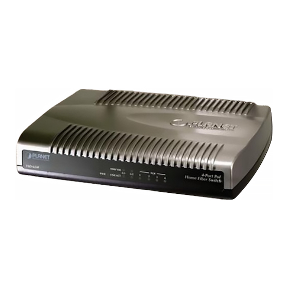
The LED Indicators are also located on the front panel of the Web Smart Switch. 4-Port POF 1000/100 Home Fiber Switch LNK/ACT Figure 2-1 FSD-624SF Switch front panel 2.1.1 LED indicators System Color Function Green Lights to indicate that the Switch has power. -
Page 9: Rear Panel
2.2 Rear Panel The rear panel of the Web Smart Switch indicates a DC power connector, which accepts input power of DC 5V 2A. Figure 2-2 FSD-624SF Switch rear panel Power Notice: 1. The device is a power-required device, it means, it will not work till it is powered. If your networks should active all the time, please consider using UPS (Uninterrupted Power Supply) for your device. - Page 10 Figure 2-3 Plug-in the SFP transceiver Approved PLANET SFP Transceivers PLANET Web Smart Switch supports both single mode and multi mode SFP transceiver. The following list of approved PLANET SFP transceivers is correct at the time of publication: ■MGB-SX SFP (1000Base-SX SFP transceiver ) ■MGB-LX SFP (1000Base-LX SFP transceiver )
- Page 11 Connect the fiber cable Attach the duplex LC connector on the network cable into the SFP transceiver. Connect the other end of the cable to a device – switches with SFP installed, fiber NIC on a workstation or a Media Converter..
-
Page 12: Switch Management
User can manage the Web Smart Switch by Web Management via a network connection. 3.2.1 Web Management The PLANET FSD-624SF provides a built-in browser interface. You can manage the Switch remotely by having a remote host with Web browser, such as Microsoft Internet Explorer, Netscape Navigator or Mozilla Firefox. -
Page 13: Planet Smart Discovery Utility
3.2.2 PLANET Smart Discovery Utility For easily list the FSD-624SF in your Ethernet environment, the Planet Smart Discovery Utility from user’s manual CD-ROM is an ideal solution. The following install instructions guiding you for run the Planet Smart Discovery Utility. -
Page 14: Logging On To The Fsd-624Sf
Figure 3-3. 7. Press “Exit” button to shutdown the planet Smart Discovery Utility. 3.3 Logging on to the FSD-624SF When you log on to the Web Smart Switch Web interface for the first time, a sign-on string appears and you are prompted for a Web login username and password. -
Page 15: Web Management
4. WEB MANAGEMENT To modify your PC’s IP domain to the same with Web Smart Switch then use the default IP address (192.168.0.100) to remote configure Web Smart Switch through the Web interface. 4.1 Login in to the Switch To access the Web-browser interface you must first enter the user name and password, the default user name and password is "admin”. - Page 16 The Switch Menu provide seven major management functions, the screen in Figure 4-2 appears. Figure 4-2 Web Main Menu Screen The seven items and it description shown as below: ◆ System: Provide System configuration of Web Smart Switch. Explained in section 4.2. ◆...
-
Page 17: System
4.2 System This section provides System Information, IP Configuration, Password Setting, Factory Default, Firmware Update and Reboot functions of Web Smart Switch, the screen in Figure 4-3 appears and Table 4-1 describes the System object of Web Smart Switch. Figure 4-3 System Web Page Screen Object Description System Information Display the MAC address, Hardware Version, and Software Version, Device Description. -
Page 18: System Information
4.2.1 System Information This section displays the MAC address, Hardware Version and Software Version, also allow define the device description and press “Apply” button to take affect. The screen in Figure 4-4 appears. Figure 4-4 System Information Web Page Screen Notice: Up to 16 characters is allowed for the Device Description. -
Page 19: Ip Configuration
4.2.2 IP Configuration This section provides change the IP Address, Subnet Mask and Gateway, the screen in Figure 4-5 appears. Figure 4-5 IP Configuration Web Page Screen .After setup complete and press “Apply” button to take affect. The following screen in Figure 4-6 appears and then another Web page login screen with new IP address will show up. -
Page 20: Password Setting
4.2.3 Password Setting This section provides change the Username and Password, the screen in Figure 4-7 appears. Figure 4-7 Password Setting Web Page Screen Notice: Up to 8 characters is allowed for the username and password assign. - 20 -... -
Page 21: Factory Default
4.2.4 Factory Default This section provides reset the Web Smart Switch to factory default mode, the screen in Figure 4-8 appears. Figure 4-8 Factory Default Web Page Screen Press “Factory Default” button to take affect. The following screen in Figure 4-9 appears and then another Web page login screen with default setting will show up. -
Page 22: Firmware Update
4.2.5 Firmware Update This section provides firmware upgrade of the Web Smart Switch, the screen in Figure 4-10 appears. Figure 4-10 Firmware Update Web Page Screen Press “Update” button for start the firmware upgrade process, the screen in Figure 4-11 & 4-12 appears. - Page 23 Figure 4-12 Firmware Update Web page Screen Then the following screen appears, press “Browser” button to find the firmware location administrator PC, the screen in Figure 4-13 appears. Figure 4-13 Firmware Update Web Page Screen - 23 -...
- Page 24 After find the firmware location from administrator PC, press “Update” button to start the firmware upgrade process. The screen in Figure 4-14 appears. Figure 4-14 Firmware Update Web Page Screen When firmware upgrade process is completed then the following screen appears, please wait for a while for system reboot.
-
Page 25: Reboot
4.2.6 Reboot This section allows reboot the Web Smart Switch, the screen in Figure 4-16 appears. Figure 4-16 Reboot Web Page Screen Press “Reboot” button to reboot the Web Smart Switch, the screen in Figure 4-17 appears. After device reboot completed, the Web login screen appears and login for further management. -
Page 26: Port Management
4.3 Port Management This section provides Port Configuration, Port Mirroring, Bandwidth Control, Broadcast Storm Control and Port Statistics from Web Smart Switch, the screen in Figure 4-18 appears and Table 4-2 describes the system object of Web Smart Switch. Figure 4-18 Port Management Web Page Screen Object Description Port Configuration... -
Page 27: Port Configuration
4.3.1 Port Configuration This section introduces detail settings of per port on Web Smart Switch; the screen in Figure 4-19 appears and Table 4-3 & descriptions the Port Configuration objects of Web Smart Switch. Figure 4-19 Port Configuration Web Page Screen Object Description Port... - Page 28 Object Description Port Indicate port 1 to port 4 and port G1, port G2. Current Status Display per port Current Status, such as Link, Speed Mode and Flow Control. Link Display current link status from each port of the Web Smart Switch. Speed Mode Display current speed mode from each port of the Web Smart Switch.
-
Page 29: Port Mirroring
4.3.2 Port Mirroring This section introduces detail settings of Port Mirroring function of Web Smart Switch; the screen in Figure 4-20 appears Table 4-5 descriptions the Port Mirroring objects of Web Smart Switch. Figure 4-20 Port Mirroring Web Page Screen Object Description Monitored Packets Provide disable and enable the Port Mirroring function, the available options are Disable, RX,... -
Page 30: Bandwidth Control
4.3.3 Bandwidth Control This section introduces detail settings of Bandwidth Control function of Web Smart Switch; the screen in Figure 4-21 appears and Table 4-6 description the Bandwidth Control objects of Web Smart Switch. Figure 4-21 Bandwidth Control Web Page Screen Object Description Port... -
Page 31: Broadcast Storm Control
4.3.4 Broadcast Storm Control This section introduces detail settings of Broadcast Storm Control function of Web Smart Switch; the screen in Figure 4-22 appears and Table 4-7 descriptions the Broadcast Storm Control objects of Web Smart Switch. Figure 4-22 Broadcast Storm Control Web Page Screen Object Description Filter Mode... -
Page 32: Port Statistics
4.3.5 Port Statistics This section introduces detail information of Port Statistics function of Web Smart Switch; the screen in Figure 4-23 pears and Table 4-8 descriptions the Port Statistics objects of Web Smart Switch. Figure 4-23 Port Statistics Web Page Screen Object Description Counter Mode... -
Page 33: Vlan Setting
4.4 VLAN Setting A Virtual LAN (VLAN) is a logical network grouping that limits the broadcast domain. It allows you to isolate network traffic so only members of the VLAN receive traffic from the same VLAN members. Basically, creating a VLAN from a switch is logically equivalent of reconnecting a group of network devices to another Layer 2 switch. - Page 34 802.1Q Tag User Priority VLAN ID (VID) 3 bits 1 bits 12 bits TPID (Tag Protocol Identifier) TCI (Tag Control Information) 2 bytes 2 bytes Destination Source Ad- Ethernet Preamble VLAN TAG Data Address dress Type 6 bytes 6 bytes 4 bytes 2 bytes 46-1517 bytes...
- Page 35 VLAN Settings This section provides VLAN Configuration from Web Smart Switch, the screen in Figure 4-24 appears and Table 4-9 describes the VLAN Configuration object of Web Smart Switch. Figure 4-24 VLAN Setting Web Page Screen Object Description VLAN Mode Provide different VLAN operation mode, the available options are shown as below: No VLAN 802.1Q VLAN.
-
Page 36: 802.1Q Vlan
4.4.1 802.1Q VLAN This section introduces detail information of IEEE 802.1Q VLAN function of Web Smart Switch; Choose “802.1Q VLAN” from VLAN from the VLAN Mode and press “Apply” button to enable the 802.1Q VLAN function. The screen in Figure 4-25 &... - Page 37 Object Description Group Display the existence 802.1Q VLAN groups. Display different VLAN ID from multi-802.1Q VLAN groups. VLAN Name Assign and display different VLAN name from multi-802.1Q VLAN groups. Up to maximum 8 char- acters allow. Port Indicate port 1 to port 4 and port G1, port G2. Member Allow to click specific port as member port from different 802.1Q VLAN groups.
-
Page 38: Port Based Vlan
4.4.2 Port Based VLAN This section introduces detail information of Port Based VLAN function of Web Smart Switch; Choose “Port Based VLAN” from VLAN from the VLAN Mode and press “Apply” button to enable the port based VLAN function. The screen in Figure 4-28 &... - Page 39 Object Description Display different VLAN ID from multi-port based VLAN groups. VLAN Name Assign and display different VLAN name from multi-port based VLAN groups. Up to maximum 8 characters allow. Port Indicate port 1 to port 4 and port G1, port G2. Member Allow to click specific port as member port from different port based VLAN groups.
-
Page 40: Mtu Vlan
4.4.3 MTU VLAN This section introduces detail information of MTU VLAN function of Web Smart Switch; Choose “MTU” from VLAN from the VLAN Mode and press “Apply” button to enable the MTU VLAN function. The screen in Figure 4-30 appears and Table 4-13 description the MTU VLAN objects of Web Smart Switch. -
Page 41: Qos Setting
4.5 QoS Setting This function provides QoS Setting of Web Smart Switch; the screen in Figure 4-31 appears and Table 4-14 descriptions the QoS Setting of Web Smart Switch. Figure 4-31 QoS Setting Web Page Screen Object Description Priority Mode Provide three different Priority polices on Web Smart Switch. -
Page 42: Priority Mode
4.5.1 Priority Mode This section introduces detail information of Priority Mode of Web Smart Switch; the screen in Figure 4-32 appears and Table 4-15 descriptions the Priority Mode of Web Smart Switch. Figure 4-32 Priority Mode Web Page Screen Object Description Priority Mode Provide three different Priority polices on Web Smart Switch, the available options are shown as... -
Page 43: Class Of Service Configuration
4.5.2 Class of Service Configuration This section introduces detail information of Class of Service Configuration of Web Smart Switch; the screen in Figure 4-33 appears and Table 4-16 descriptions the Class of Service Configuration of Web Smart Switch. Figure 4-33 Class of Service Configuration Web Page Screen Object Description Enable High Priority... - Page 44 IP TOS/DSCP Priority value define TOS/DSCP Value AF11 AF21 AF31 AF41 High Priority DSCP 46 DSCP 10 DSCP 18 DSCP 26 DSCP 34 (101110) (001010) (010010) (011010) (100010) Low Priority Other DSCP values DSCP: Differentiated Services Code Point EF: Expected Forwarding AF: Assured Forwarding - 44 -...
-
Page 45: Tcp / Udp Port Based Qos
4.5.3 TCP / UDP Port Based QoS This section introduces detail information of TCP / UDP Port Based QoS Configuration of Web Smart Switch; the screen in Figure 4-34 & 4-35 appears and Table 4-17 descriptions the TCP / UDP Port Based QoS Configuration of Web Smart Switch. - Page 46 Object Description Protocol Display different Protocol for define the QoS policy in option FTP(20,21) Provide F-I-F-O, Discard, Low, High options. SSH(22) Provide F-I-F-O, Discard, Low, High options. TELNET(23) Provide F-I-F-O, Discard, Low, High options. SMTP(25) Provide F-I-F-O, Discard, Low, High options. DNS(53) Provide F-I-F-O, Discard, Low, High options.
-
Page 47: Security Filter
4.6 Security Filter This function provides Security Filter of Web Smart Switch; the screen in Figure 4-36 appears and Table 4-18 descriptions the Security Filter of Web Smart Switch. Figure 4-36 Security Filter Web Page Screen Object Description MAC Address Filter Allow define three MAC Address on per port of Web Smart Switch. -
Page 48: Mac Address Filter
4.6.1 MAC Address Filter This section introduces detail information of MAC Address Filter of Web Smart Switch; the screen in Figure 4-37 appears Table 4-19 & 4-20 descriptions the MAC Address Filter of Web Smart Switch. Figure 4-37 MAC Address Filter Web Page Screen Object Description MAC Address... -
Page 49: Tcp / Udp Filter
4.6.2 TCP / UDP Filter This section introduces detail information of TCP / UDP Filter of Web Smart Switch; the screen in Figure 4-38 appears and Table 4-21 descriptions the TCP / UDP Filter Configuration of Web Smart Switch. Figure 4-38 TCP / UDP Filter Web Page Screen - 49 -... - Page 50 Object Description Function Enable Allow to Disable or Enable the TCP / UDP Filter function. Default mode is Disable. Port Filtering Rule Allow to Forward or Block the Port Filtering Rule. Default mode is Block. Protocol Display different Protocol for define the TCP / UDP Filter policy. FTP(20,21) SSH(22) TELNET(23)
-
Page 51: Misc Operation
4.7 Misc Operation This function provides Misc Operation of Web Smart Switch; the screen in Figure 4-39 appears and Table 4-22 descrip- tions the Misc Operation of Web Smart Switch. Figure 4-39 Misc Operation Web Page Screen Object Description Output Queue Aging Time Allow define the Output Queue Aging Time of Web Smart Switch, the available options are Disable, 200ms, 400ms, 600ms and 800ms. -
Page 52: Logout
4.8 Logout This section provide Web logout function on Web Smart Switch, after choose this function and the following screen appears Figure 4-40 & 4-41. Please press “Logout” button to take effect and Login Web Screen appears. Please re-login the Web Smart Switch for further management. -
Page 53: Switch Operation
5. SWITCH OPERATION 5.1 Address Table The Switch is implemented with an address table. This address table composed of many entries. Each entry is used to store the address information of some node in network, including MAC address, port no, etc. This information comes from the learning process of Ethernet Switch. -
Page 54: Troubleshooting
Check the LNK/ACT LED of 1000Base-T port on the switch and Make sure the cable is installed properly. Also make sure the cable is the right type, turn off the power. After a while, turn on power again. How to deal forgotten password situation of FSD-624SF? Solution:... -
Page 55: Appendix A Networking Connection
APPENDIX A NETWORKING CONNECTION A.1 Switch‘s RJ-45 Pin Assignments 1000Mbps, 1000Base-T RJ-45 Connector pin assignment Contact MDI-X BI_DA+ BI_DB+ BI_DA- BI_DB- BI_DB+ BI_DA+ BI_DC+ BI_DD+ BI_DC- BI_DD- BI_DB- BI_DA- BI_DD+ BI_DC+ BI_DD- BI_DC- 10/100Mbps, 10/100Base-TX RJ-45 Connector pin assignment MDI-X Contact Media Dependant In- Media Dependant... -
Page 56: 100Mbps, 100Base-Fx, Smi Type Connector
Please make sure your connected cables are with same pin assignment and color as above picture before deploying the cables into your network. A.3 100Mbps, 100Base-FX, SMI type connector The FSD-624SF is using Optolock POF connector that is mostly being used for IEEE1394b transmission. The followings show the basic information and its installation. Basic Information: The Optolock POF connector will as like following screen. - Page 57 Installation: Pull out the Optolock POF connector and connect the POF cable to the POF connector, the screen appears in following. → Figure A-4: Optolock POF connector installation Pull in the Optolock POF connector and the screen in following screen appears. Figure A-5: Optolock POF connector installation 2080-A33190-000 - 57 -...
-
Page 58: Ec Declaration Of Conformity
EC Declaration of Conformity For the following equipment: *Type of Product: 4-Port 100Base-FX POF + 2 Gigabit Web Smart Switch *Model Number: FSD-624SF * Produced by: Manufacturer‘s Name : Planet Technology Corp. Manufacturer‘s Address: 11F, No 96, Min Chuan Road Hsin Tien, Taipei, Taiwan , R.
Need help?
Do you have a question about the FSD-624SF and is the answer not in the manual?
Questions and answers