Table of Contents
Advertisement
Quick Links
Advertisement
Table of Contents
Troubleshooting

Related Manuals for ZyXEL Communications MES3500 Series


Summary of Contents for ZyXEL Communications MES3500 Series
- Page 1 MES3500/MGS3520 Series Layer 2 Management Switch Version 4.10 Edition 1, 05/2015 Quick Start Guide User’s Guide Default Login Details LAN IP Address http://192.168.1.1 User Name admin Password 1234 www.zyxel.com Copyright © 2015 ZyXEL Communications Corporation...
- Page 2 IMPORTANT! READ CAREFULLY BEFORE USE. KEEP THIS GUIDE FOR FUTURE REFERENCE. Screenshots and graphics in this book may differ slightly from your product due to differences in your product firmware or your computer operating system. Every effort has been made to ensure that the information in this manual is accurate.
-
Page 3: Table Of Contents
Contents Overview Contents Overview User’s Guide ............................16 Getting to Know Your Switch ........................17 Hardware Installation and Connection ....................22 Hardware Overview ..........................25 The Web Configurator ..........................35 Initial Setup Example ..........................43 Tutorials ..............................47 Technical Reference ..........................72 System Status and Port Statistics ......................73 Basic Setting ............................78 VLAN ...............................89 Static MAC Forward Setup ........................105... - Page 4 Contents Overview DHCP ..............................260 Maintenance ............................268 Access Control ............................274 Diagnostic .............................301 Syslog ..............................302 Cluster Management ..........................305 MAC Table ............................. 311 ARP Table .............................314 Configure Clone ............................316 Troubleshooting ............................318 MES3500/MGS3520 Series User’s Guide...
-
Page 5: Table Of Contents
Table of Contents Table of Contents Contents Overview ..........................3 Table of Contents ..........................5 Part I: User’s Guide ..................16 Chapter 1 Getting to Know Your Switch......................17 1.1 Introduction ............................17 1.1.1 Backbone Application ......................17 1.1.2 Bridging Example ........................18 1.1.3 High Performance Switching Example ..................18 1.1.4 IEEE 802.1Q VLAN Application Examples ................19 1.1.5 IPv6 Support ..........................20 1.2 Ways to Manage the Switch ......................20... - Page 6 Table of Contents 4.1 Introduction ............................35 4.2 System Login ..........................35 4.3 The Web Configurator Layout ......................36 4.3.1 Change Your Password ......................39 4.4 Saving Your Configuration ........................40 4.5 Switch Lockout ..........................40 4.6 Resetting the Switch ........................41 4.6.1 Reload the Configuration File ....................41 4.7 Logging Out of the Web Configurator ....................42 4.8 Help ..............................42 Chapter 5...
- Page 7 Table of Contents 7.1 Overview ............................73 7.2 Port Status Summary ........................73 7.2.1 Status: Port Details ......................74 Chapter 8 Basic Setting ............................78 8.1 Overview ............................78 8.2 System Information ........................78 8.3 General Setup ..........................79 8.4 Introduction to VLANs ........................81 8.4.1 Smart Isolation .........................82 8.5 Switch Setup ..........................83 8.6 IP Setup ............................85...
- Page 8 Table of Contents Chapter 11 Static Multicast Forward Setup .......................107 11.1 Static Multicast Forwarding Overview ...................107 11.2 Configuring Static Multicast Forwarding ..................108 Chapter 12 Filtering.............................. 110 12.1 Configure a Filtering Rule ......................110 Chapter 13 Spanning Tree Protocol........................112 13.1 STP/RSTP Overview ........................112 13.1.1 STP Terminology ........................
- Page 9 Table of Contents 17.1 Link Aggregation Overview ......................137 17.2 Dynamic Link Aggregation ......................137 17.2.1 Link Aggregation ID ......................138 17.3 Link Aggregation Status .......................138 17.4 Link Aggregation Setting ......................139 17.5 Link Aggregation Control Protocol .....................141 17.6 Static Trunking Example .......................142 Chapter 18 Port Authentication ..........................144 18.1 Port Authentication Overview .......................144 18.1.1 IEEE 802.1x Authentication ....................144...
- Page 10 Table of Contents 22.1.2 Weighted Fair Queuing ......................165 22.1.3 Weighted Round Robin Scheduling (WRR) .................166 22.2 Configuring Queuing ........................166 Chapter 23 VLAN Stacking ..........................168 23.1 VLAN Stacking Overview ......................168 23.1.1 VLAN Stacking Example ......................168 23.2 VLAN Stacking Port Roles ......................169 23.3 VLAN Tag Format ..........................169 23.3.1 Frame Format ........................170 23.4 Configuring VLAN Stacking ......................170...
- Page 11 Table of Contents 25.2.4 Vendor Specific Attribute .....................197 25.2.5 Tunnel Protocol Attribute .....................198 25.3 Supported RADIUS Attributes .......................198 25.3.1 Attributes Used for Authentication ..................199 25.3.2 Attributes Used for Accounting ....................199 Chapter 26 IP Source Guard..........................202 26.1 IP Source Guard Overview ......................202 26.1.1 DHCP Snooping Overview ....................202 26.1.2 ARP Inspection Overview ....................204 26.2 IP Source Guard ...........................206...
- Page 12 Table of Contents 30.1 sFlow Overview ..........................231 30.2 sFlow Port Configuration .......................231 30.2.1 sFlow Collector Configuration ....................233 Chapter 31 PPPoE ..............................235 31.1 PPPoE Intermediate Agent Overview ..................235 31.1.1 PPPoE Intermediate Agent Tag Format ................235 31.1.2 Sub-Option Format ......................235 31.1.3 Port State ..........................236 31.2 The PPPoE Screen ........................237 31.3 PPPoE Intermediate Agent ......................237 31.3.1 PPPoE IA Per-Port ......................239...
- Page 13 Table of Contents 35.3 Activating DiffServ ........................254 35.3.1 Configuring 2-Rate 3 Color Marker Settings ...............255 35.3.2 Configuring DSCP Profiles ....................257 35.4 DSCP-to-IEEE 802.1p Priority Settings ..................258 35.4.1 Configuring DSCP Settings ....................258 Chapter 36 DHCP..............................260 36.1 DHCP Overview ...........................260 36.1.1 DHCP Modes ........................260 36.1.2 DHCP Configuration Options ....................260 36.2 DHCP Status ..........................260 36.2.1 Option 82 Profile ........................261...
- Page 14 Table of Contents 38.3.4 Configuring SNMP ......................285 38.3.5 Configuring SNMP Trap Group ..................287 38.3.6 Enabling/Disabling Sending of SNMP Traps on a Port ............288 38.3.7 Configuring SNMP User ....................289 38.4 Setting Up Login Accounts ......................291 38.5 SSH Overview ..........................292 38.6 How SSH works ..........................292 38.7 SSH Implementation on the Switch ....................293 38.7.1 Requirements for Using SSH ....................294 38.8 Introduction to HTTPS ........................294...
- Page 15 Table of Contents 43.2 The ARP Table Screen .........................314 Chapter 44 Configure Clone..........................316 44.1 Configure Clone ...........................316 Chapter 45 Troubleshooting..........................318 45.1 Power, Hardware Connections, and LEDs ..................318 45.2 Switch Access and Login ......................319 45.3 Switch Configuration ........................321 Appendix A Common Services ......................322 Appendix B Legal Information......................325 Index ..............................330 MES3500/MGS3520 Series User’s Guide...
-
Page 16: User's Guide
User’s Guide... -
Page 17: Getting To Know Your Switch
H A PT ER Getting to Know Your Switch This chapter introduces the main features and applications of the Switch. 1.1 Introduction The Switch is a layer-2 standalone Ethernet switch. The Switch has two or four GbE dual personality interfaces with each interface comprising one mini-GBIC slot and one 100/1000 Mbps RJ-45 port, with either port or slot active at a time. -
Page 18: Bridging Example
Chapter 1 Getting to Know Your Switch In this example, all computers can share high-speed applications on the server. To expand the network, simply add more networking devices such as switches, routers, computers, print servers etc. Figure 1 Backbone Application 1.1.2 Bridging Example In this example, the Switch connects different company departments (RD and Sales) to the corporate backbone. -
Page 19: Ieee 802.1Q Vlan Application Examples
Chapter 1 Getting to Know Your Switch Switching to higher-speed LANs such as ATM (Asynchronous Transmission Mode) is not feasible for most people due to the expense of replacing all existing Ethernet cables and adapter cards, restructuring your network and complex maintenance. The Switch can provide the same bandwidth as ATM at much lower cost while still being able to use existing adapters and switches. -
Page 20: Ipv6 Support
Chapter 1 Getting to Know Your Switch Figure 4 Shared Server Using VLAN Example 1.1.5 IPv6 Support IPv6 (Internet Protocol version 6), is designed to enhance IP address size and features. The increase in IPv6 address size to 128 bits (from the 32-bit IPv4 address) allows up to 3.4 x 10 addresses. -
Page 21: Good Habits For Managing The Switch
Chapter 1 Getting to Know Your Switch 1.3 Good Habits for Managing the Switch Do the following things regularly to make the Switch more secure and to manage the Switch more effectively. • Change the password. Use a password that’s not easy to guess and that consists of different types of characters, such as numbers and letters. -
Page 22: Hardware Installation And Connection
H A PT ER Hardware Installation and Connection This chapter shows you how to install and connect the Switch. 2.1 Installation Scenarios The Switch can be placed on a desktop or rack-mounted on a standard EIA rack. Use the rubber feet in a desktop installation and the brackets in a rack-mounted installation. -
Page 23: Attaching The Mounting Brackets To The Switch
Chapter 2 Hardware Installation and Connection 2.3.1.1 Precautions • Make sure the rack will safely support the combined weight of all the equipment it contains. • Make sure the position of the Switch does not make the rack unstable or top-heavy. Take all necessary precautions to anchor the rack securely before installing the unit. - Page 24 Chapter 2 Hardware Installation and Connection Figure 6 Mounting the Switch on a Rack Using a #2 Philips screwdriver, install the M5 flat head screws through the mounting bracket holes into the rack. Repeat steps to attach the second mounting bracket on the other side of the rack. MES3500/MGS3520 Series User’s Guide...
-
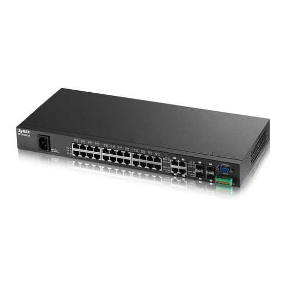
Page 25: Hardware Overview
H A PT ER Hardware Overview This chapter describes the front panel and rear panel of the Switch and shows you how to make the hardware connections. 3.1 Front Panel The following figure shows the front panel of the Switch. Figure 7 MES3500-24 Front Panel: AC Model Dual Personality Interfaces LEDs... - Page 26 Chapter 3 Hardware Overview Figure 10 MES3500-24F Front Panel: DC Model Dual Personality Interfaces Power Switch Console Port LEDs Signal slot Power Connection SFP Slots Figure 11 MES3500-10 Front Panel: AC Model Dual Personality Interfaces LEDs Console Port Power Connection Signal slot Fast Ethernet Ports Figure 12 MGS3520-28 Front Panel: AC/DC Model...
-
Page 27: Console Port
Chapter 3 Hardware Overview Figure 14 MGS3520-50 Front Panel: AC/DC Model Dual Personality Interfaces Power Switch SFP slot Gigabit Ethernet Ports LEDs Figure 15 MGS3520-50 Rear Panel: AC/DC Model AC Power Connection DC Power Connection Console Port Signal slot The following table describes the port labels on the front panel. Table 2 Front Panel Connections LABEL DESCRIPTION... -
Page 28: Ethernet Ports
Chapter 3 Hardware Overview • VT100 • Terminal emulation • 9600 bps • No parity, 8 data bits, 1 stop bit • No flow control Connect the male 9-pin end of the console cable to the console port of the Switch. Connect the female end to a serial port (COM1, COM2 or other COM port) of your computer. -
Page 29: Transceiver Slots
Chapter 3 Hardware Overview 3.1.3 Transceiver Slots These are slots for mini-GBIC (Gigabit Interface Converter) transceivers or 100 Mbps Small Form- factor Pluggable (SFP) transceivers. A transceiver is a single unit that houses a transmitter and a receiver. The Switch does not come with transceivers. You must use transceivers that comply with the SFP Transceiver MultiSource Agreement (MSA). -
Page 30: Power Connector
Chapter 3 Hardware Overview Open the transceiver’s latch (latch styles vary). Pull the transceiver out of the slot. Figure 18 Removing the Fiber Optic Cables Figure 19 Opening the Transceiver’s Latch Example Figure 20 Transceiver Removal Example 3.1.4 Power Connector Make sure you are using the correct power source as shown on the panel and that no objects obstruct the airflow of the fans. -
Page 31: Signal Slot
Chapter 3 Hardware Overview 3.1.4.2 DC Power Connection The Switch uses a single ETB series terminal block plug with four pins which allows you to connect up to two separate power supplies. If one power supply fails the system can operate on the remaining power supply. - Page 32 Chapter 3 Hardware Overview Use a connector to connect wires of the correct gauge (18 AWG or larger) to the sensor’s signal output pins. Check the sensor’s documentation to identify its two signal output pins. Connect these two wires to any one of the following pairs of signal input pins on the Switch’s Signal connector--(4,5) (6,7) (8,9) (10,11).
-
Page 33: Leds
Chapter 3 Hardware Overview Figure 22 Daisy-chaining an External Alarm Sensor to Other Switches of the Same Model ..11 10 ..11 10 ..11 10 Pin Assignments 3.2 LEDs After you connect the power to the Switch, view the LEDs to ensure proper functioning of the Switch and as an aid in troubleshooting. - Page 34 Chapter 3 Hardware Overview Table 3 LED Descriptions (continued) COLOR STATUS DESCRIPTION 1 ~ 24 Amber The port has a successfule connection. No Ethernet device is connected to this port. Blinking This port is receiving or transmitting data. 100/1000 Mbps SFP Slots (MGS3520-28F) 1 ~ 24 Green The port has a successful 1000 Mbps connection.
-
Page 35: The Web Configurator
H A PT ER The Web Configurator This section introduces the configuration and functions of the web configurator. 4.1 Introduction The web configurator is an HTML-based management interface that allows easy Switch setup and management via Internet browser. Use Internet Explorer 6.0 and later or Firefox 2.0 and later versions. -
Page 36: The Web Configurator Layout
Chapter 4 The Web Configurator Figure 23 Web Configurator: Login Click OK to view the first web configurator screen. 4.3 The Web Configurator Layout The Status screen is the first screen that displays when you access the web configurator. This guide uses the MES3500-24 screens as an example. - Page 37 Chapter 4 The Web Configurator B, C, D, E - These are quick links which allow you to perform certain tasks no matter which screen you are currently working in. B - Click this link to save your configuration into the Switch’s nonvolatile memory. Nonvolatile memory is saved in the configuration file from which the Switch booted from and it stays the same even if the Switch’s power is turned off.
- Page 38 Chapter 4 The Web Configurator Table 5 Navigation Panel Links (continued) LINK DESCRIPTION General Setup This link takes you to a screen where you can configure general identification information and time settings for the Switch. Switch Setup This link takes you to a screen where you can set up global Switch parameters such as VLAN type, MAC address learning, GARP and priority queues.
-
Page 39: Change Your Password
Chapter 4 The Web Configurator Table 5 Navigation Panel Links (continued) LINK DESCRIPTION VLAN Mapping This link takes you to screens where you can configure VLAN mapping settings on the Switch. Layer 2 Protocol This link takes you to a screen where you can configure L2PT (Layer 2 Protocol Tunneling) Tunneling settings on the Switch. -
Page 40: Saving Your Configuration
Chapter 4 The Web Configurator Figure 25 Change Administrator Login Password 4.4 Saving Your Configuration When you are done modifying the settings in a screen, click Apply to save your changes back to the run-time memory. Settings in the run-time memory are lost when the Switch’s power is turned off. -
Page 41: Resetting The Switch
Chapter 4 The Web Configurator Forget the password and/or IP address. Prevent all services from accessing the Switch. Change a service port number but forget it. Note: Be careful not to lock yourself and others out of the Switch. If you do lock yourself out, try using out-of-band management (via the management port) to configure the Switch. -
Page 42: Logging Out Of The Web Configurator
Chapter 4 The Web Configurator Figure 26 Resetting the Switch: Via the Console Port Bootbase Version: V1.00 | 11/02/2011 11:09:37 RAM: Size = 65536 Kbytes DRAM POST: Testing: 65536K DRAM Test SUCCESS ! ZyNOS Version: MES3500-24_4.00(AABB.0)b1 | 11/04/2011 17:32:28 Press any key to enter debug mode within 3 seconds............. -
Page 43: Initial Setup Example
H A PT ER Initial Setup Example This chapter shows how to set up the Switch for an example network. 5.1 Overview The following lists the configuration steps for the initial setup: • Create a VLAN • Set port VLAN ID •... -
Page 44: Setting Port Vid
Chapter 5 Initial Setup Example In the Static VLAN screen, select ACTIVE, enter a descriptive name in the Name field and enter 2 in the VLAN Group ID field for the VLAN2 network. Note: The VLAN Group ID field in this screen and the VID field in the IP Setup screen refer to the same VLAN ID. -
Page 45: Configuring Switch Management Ip Address
Chapter 5 Initial Setup Example Figure 29 Initial Setup Network Example: Port VID Click Advanced Applications > VLAN in the navigation panel. Then click the VLAN Port Setting link. Enter 2 in the PVID field for port 1 and click Apply to save your changes back to the run-time memory. - Page 46 Chapter 5 Initial Setup Example Open your web browser and enter 192.168.1.1 (the default management IP address) in the address bar to access the web configurator. See Section 4.2 on page 35 for more information. Click Basic Setting > IP Setup in the navigation panel.
-
Page 47: Tutorials
H A PT ER Tutorials This chapter provides some examples of using the web configurator to set up and use the Switch. The tutorials include: • How to Use DHCP Snooping on the Switch • How to Use DHCP Relay on the Switch •... - Page 48 Chapter 6 Tutorials Go to Advanced Application > VLAN > Static VLAN, and create a VLAN with ID of 100. Add ports 5, 6 and 7 in the VLAN by selecting Fixed in the Control field as shown. Deselect Tx Tagging because you don’t want outgoing traffic to contain this VLAN tag. Click Add.
- Page 49 Chapter 6 Tutorials Click the Port link at the top right corner. The DHCP Snooping Port Configure screen appears. Select Trusted in the Server Trusted state field for port 5 because the DHCP server is connected to port 5. Keep ports 6 and 7 Untrusted because they are connected to DHCP clients. Click Apply. Go to Advanced Application >...
-
Page 50: How To Use Dhcp Relay On The Switch
Chapter 6 Tutorials Click Save at the top right corner of the web configurator to save the configuration permanently. Connect your DHCP server to port 5 and a computer (as DHCP client) to either port 6 or 7. The computer should be able to get an IP address from the DHCP server. If you put the DHCP server on port 6 or 7, the computer will not able to get an IP address. -
Page 51: Creating A Vlan
Chapter 6 Tutorials DHCP Server Port 2 192.168.2.3 PVID=102 VLAN 102 172.16.1.18 6.2.2 Creating a VLAN Follow the steps below to configure port 2 as a member of VLAN 102. Access the web configurator through the Switch’s port which is not in VLAN 102. Go to Basic Setting >... - Page 52 Chapter 6 Tutorials Click Add to save the settings to the run-time memory. Settings in the run-time memory are lost when the Switch’s power is turned off. Click the VLAN Status link in the Static VLAN screen and then the VLAN Port Setting link in the VLAN Status screen.
-
Page 53: Configuring Dhcp Relay
Chapter 6 Tutorials 11 Click the Save link in the upper right corner of the web configurator to save your configuration permanently. 6.2.3 Configuring DHCP Relay Follow the steps below to enable DHCP relay on the Switch and allow the Switch to add relay agent information (such as the VLAN ID) to DHCP requests. -
Page 54: Troubleshooting
Chapter 6 Tutorials Click the Save link in the upper right corner of the web configurator to save your configuration permanently. The DHCP server can then assign a specific IP address based on the DHCP request. 6.2.4 Troubleshooting Check the client A’s IP address. If it did not receive the IP address 172.16.1.18, make sure: Client A is connected to the Switch’s port 2 in VLAN 102. -
Page 55: Configuring Switch A
Chapter 6 Tutorials Note: For related information about PPPoE IA, see Section 31.3 on page 237. The settings in this tutorial are as follows: Table 7 Settings in this Tutorial SWITCH PORT CONNECTED VLAN CIRCUIT-ID REMOTE-ID PPPOE IA PORT TRUSTED Port 5 (to C) userC 00134900000A... - Page 56 Chapter 6 Tutorials Then Click Intermediate Agent on the top of the screen. The Intermediate Agent screen appears. Click VLAN on the top of the screen. Enter 1 for both Start VID and End VID since both the Switch and PPPoE server are in VLAN 1 in this example.
-
Page 57: Configuring Switch B
Chapter 6 Tutorials Then select Yes to enable PPPoE IA in VLAN 1 and also select Circuit-id and Remote-id to allow the Switch to add these two strings to frames tagged with VLAN 1 and pass to the PPPoE server. Click Apply. - Page 58 Chapter 6 Tutorials Click Port on the top of the screen. Select Trusted for ports 11 and 12 and then click Apply. Then Click Intermediate Agent on the top of the screen. The Intermediate Agent screen appears. Click VLAN on the top of the screen. MES3500/MGS3520 Series User’s Guide...
- Page 59 Chapter 6 Tutorials Enter 1 for both Start VID and End VID. Click Apply. Then select Yes to enable PPPoE IA in VLAN 1 and also select Circuit-id and Remote-id to allow the Switch to add these two strings to frames tagged with VLAN 1 and pass to the PPPoE server. Click Apply.
-
Page 60: How To Use Error Disable And Recovery On The Switch
Chapter 6 Tutorials The settings are completed now. If you miss some settings above, subscriber C could not successfully receive an IP address assigned by the PPPoE Server. If this happens, make sure you follow the steps exactly in this tutorial. 6.4 How to Use Error Disable and Recovery on the Switch This tutorial shows you how to shut down a port when: •... - Page 61 Chapter 6 Tutorials Click Advanced Application > Errdisable > Errdisable Detect, select Active for cause ARP and inactive-port as the mode. Then click Apply. Click Advanced Application > Errdisable > Errdisable Recovery, select Active and Timer Status for loopguard and ARP entries. Also enter 180 (180 seconds = 3 minutes) in the Interval field for both entries.
-
Page 62: How To Set Up A Guest Vlan
Chapter 6 Tutorials 6.5 How to Set Up a Guest VLAN All ports on the Switch are in VLAN 1 by default. Say you enable IEEE 802.1x authentication on ports 1 to 8. Clients that connect to these ports should provide the correct user name and password in order to access the ports. - Page 63 Chapter 6 Tutorials Click Advanced Application > VLAN > Static VLAN. In the Static VLAN screen, select ACTIVE, enter a descriptive name (VLAN 200 for example) in the Name field and enter 200 in the VLAN Group ID field. Select Fixed to configure ports 1, 2, 3 and 10 to be permanent members of this VLAN. Clear the TX Tagging check box to set the Switch to remove VLAN tags before sending frames out of these ports.
- Page 64 Chapter 6 Tutorials Click the VLAN Status link in the Static VLAN screen and then the VLAN Port Setting link in the VLAN Status screen. Enter 200 in the PVID field for ports 1, 2, 3 and 10 to add a tag to incoming untagged frames received on these ports so that the frames are forwarded to the VLAN group that the tag defines.
-
Page 65: Enabling Ieee 802.1X Port Authentication
Chapter 6 Tutorials 11 Click the Save link in the upper right corner of the web configurator to save your configuration permanently. 6.5.2 Enabling IEEE 802.1x Port Authentication Follow the steps below to enable port authentication to validate access to ports 1~8 to clients based on a RADIUS server. -
Page 66: Enabling Guest Vlan
Chapter 6 Tutorials 6.5.3 Enabling Guest VLAN Click the Guest Vlan link in the 802.1x screen. Select Active and enter the guest VLAN ID (200 in this example) on ports 1, 2 and 3. The Switch puts unauthenticated clients in the specified guest VLAN. Set Host-mode to Multi-Secure to have the Switch authenticate each client that connects to one of these ports, and specify the maximum number of clients that the Switch will authenticate on each of these port (5 in this example). -
Page 67: How To Do Port Isolation In A Vlan
Chapter 6 Tutorials Click the Save link in the upper right corner of the web configurator to save your configuration permanently. Clients that attach to port 1, 2 or 3 and fail to authenticate with the RADIUS server now should be in VLAN 200 and can access the Internet, but cannot communicate with devices in VLAN 1. -
Page 68: Creating A Vlan
Chapter 6 Tutorials 6.6.1 Creating a VLAN Follow the steps below to configure port 2, 3, 4 and 25 as a member of VLAN 123. Access the web configurator through the Switch’s port which is not in VLAN 123. Go to Basic Setting > Switch Setup and set the VLAN type to 802.1Q. Click Apply to save the settings to the run-time memory. - Page 69 Chapter 6 Tutorials Click the VLAN Status link in the Static VLAN screen and then the VLAN Port Setting link in the VLAN Status screen. Enter 123 in the PVID field for ports 2, 3, 4 and 25 to add a tag to incoming untagged frames received on these ports so that the frames are forwarded to the VLAN group that the tag defines.
-
Page 70: Creating A Private Vlan Rule
Chapter 6 Tutorials 11 Click the Save link in the upper right corner of the web configurator to save your configuration permanently. 6.6.2 Creating a Private VLAN Rule Follow the steps below to configure private VLAN for VLAN 123. Click Advanced Application > Private VLAN. In the Private VLAN screen, select Active. - Page 71 Chapter 6 Tutorials Click the Save link in the upper right corner of the web configurator to save your configuration permanently. Ports 2, 3 and 4 in this VLAN will be added to the isolated port list automatically and cannot send traffic to each other.
-
Page 72: Technical Reference
Technical Reference... -
Page 73: System Status And Port Statistics
H A PT ER System Status and Port Statistics This chapter describes the system status (web configurator home page) and port details screens. 7.1 Overview The home screen of the web configurator displays a port statistical summary with links to each port showing statistical details. -
Page 74: Status: Port Details
Chapter 7 System Status and Port Statistics Table 8 Status (continued) LABEL DESCRIPTION Link This field displays the speed (either 10M for 10Mbps, 100M for 100Mbps or 1000M for 1000Mbps) and the duplex (F for full duplex or H for half). It also shows the cable type (Copper or Fiber) for the combo ports. - Page 75 Chapter 7 System Status and Port Statistics Figure 32 Status > Port Details The following table describes the labels in this screen. Table 9 Status: Port Details LABEL DESCRIPTION Port Info Port NO. This field displays the port number you are viewing. Name This field displays the name of the port.
- Page 76 Chapter 7 System Status and Port Statistics Table 9 Status: Port Details (continued) LABEL DESCRIPTION Errors This field shows the number of received errors on this port. Tx KB/s This field shows the number kilobytes per second transmitted on this port. Rx KB/s This field shows the number of kilobytes per second received on this port.
- Page 77 Chapter 7 System Status and Port Statistics Table 9 Status: Port Details (continued) LABEL DESCRIPTION 1024-1518 This field shows the number of packets (including bad packets) received that were between 1024 and 1518 octets in length. Giant This field shows the number of packets (including bad packets) received that were between 1519 octets and the maximum frame size.
-
Page 78: Basic Setting
H A PT ER Basic Setting This chapter describes how to configure the System Info, General Setup, Switch Setup, IP Setup and Port Setup screens. 8.1 Overview The System Info screen displays general Switch information (such as firmware version number) and hardware polling information (such as temperatures). -
Page 79: General Setup
Chapter 8 Basic Setting The following table describes the labels in this screen. Table 10 Basic Setting > System Info LABEL DESCRIPTION System Name This field displays the descriptive name of the Switch for identification purposes. Product Model This field displays the model number of the Switch. ZyNOS F/W This field displays the version number of the Switch 's current firmware including the date Version... - Page 80 Chapter 8 Basic Setting Figure 34 Basic Setting > General Setup The following table describes the labels in this screen. Table 11 Basic Setting > General Setup LABEL DESCRIPTION System Name Choose a descriptive name for identification purposes. This name consists of up to 64 printable characters;...
-
Page 81: Introduction To Vlans
Chapter 8 Basic Setting Table 11 Basic Setting > General Setup (continued) LABEL DESCRIPTION Current Time This field displays the time you open this menu (or refresh the menu). New Time Enter the new time in hour, minute and second format. The new time then appears in the (hh:min:ss) Current Time field after you click Apply. -
Page 82: Smart Isolation
Chapter 8 Basic Setting VLAN also increases network performance by limiting broadcasts to a smaller and more manageable logical broadcast domain. In traditional switched environments, all broadcast packets go to each and every individual port. With VLAN, all broadcasts are confined to a specific broadcast domain. -
Page 83: Switch Setup
Chapter 8 Basic Setting You should enable RSTP or MRSTP before you can use smart isolation on the Switch. If the network topology changes, the Switch automatically updates the isolated port list with the latest designated port information. Note: The uplink port connected to the Internet should be the root port. Otherwise, with smart isolation enabled, the isolated ports cannot access the Internet. - Page 84 Chapter 8 Basic Setting Table 12 Basic Setting > Switch Setup (continued) LABEL DESCRIPTION Aging Time Enter a time from 10 to 3000 seconds. This is how long all dynamically learned MAC addresses remain in the MAC address table before they age out (and must be relearned). GARP Timer: Switches join VLANs by making a declaration.
-
Page 85: Ip Setup
Chapter 8 Basic Setting 8.6 IP Setup Use the IP Setup screen to configure the Switch IP address, default gateway device, the default domain name server and the management VLAN ID. The default gateway specifies the IP address of the default gateway (next hop) for outgoing traffic. 8.6.1 Management IP Addresses The Switch needs an IP address for it to be managed over the network. - Page 86 Chapter 8 Basic Setting The following table describes the labels in this screen. Table 13 Basic Setting > IP Setup LABEL DESCRIPTION Domain Name DNS (Domain Name System) is for mapping a domain name to its corresponding IP Server address and vice versa. Enter a domain name server IP address in order to be able to use a domain name instead of an IP address.
-
Page 87: Port Setup
Chapter 8 Basic Setting Table 13 Basic Setting > IP Setup (continued) LABEL DESCRIPTION Delete Check the management IP addresses that you want to remove in the Delete column, then click the Delete button. Cancel Click Cancel to clear the selected check boxes in the Delete column. 8.7 Port Setup Use this screen to configure Switch port settings. - Page 88 Chapter 8 Basic Setting Table 14 Basic Setting > Port Setup (continued) LABEL DESCRIPTION Speed/Duplex Select the speed and the duplex mode of the Ethernet connection on this port. Choices are Auto, 10M/Half Duplex, 10M/Full Duplex, 100M/Half Duplex, 100M/Full Duplex and 1000M/Full Duplex (Gigabit connections only).
-
Page 89: Vlan
H A PT ER VLAN The type of screen you see here depends on the VLAN Type you selected in the Switch Setup screen. This chapter shows you how to configure 802.1Q tagged and port-based VLANs.? 9.1 Introduction to IEEE 802.1Q Tagged VLANs A tagged VLAN uses an explicit tag (VLAN ID) in the MAC header to identify the VLAN membership of a frame across bridges - they are not confined to the switch on which they were created. -
Page 90: Automatic Vlan Registration
Chapter 9 VLAN 9.2 Automatic VLAN Registration GARP and GVRP are the protocols used to automatically register VLAN membership across switches. 9.2.1 GARP GARP (Generic Attribute Registration Protocol) allows network switches to register and de-register attribute values with other GARP participants within a bridged LAN. GARP is a protocol that provides a generic mechanism for protocols that serve a more specific application, for example, GVRP. -
Page 91: Port Vlan Trunking
Chapter 9 VLAN 9.3 Port VLAN Trunking Enable VLAN Trunking on a port to allow frames belonging to unknown VLAN groups to pass through that port. This is useful if you want to set up VLAN groups on end devices without having to configure the same VLAN groups on intermediary devices. -
Page 92: Vlan Status
Chapter 9 VLAN 9.5.1 VLAN Status Section 9.1 on page 89 for more information on Static VLAN. Click Advanced Application > VLAN from the navigation panel to display the VLAN Status screen as shown next. Figure 40 Advanced Application > VLAN: VLAN Status The following table describes the labels in this screen. -
Page 93: Configure A Static Vlan
Chapter 9 VLAN Figure 41 Advanced Application > VLAN > VLAN Detail The following table describes the labels in this screen. Table 17 Advanced Application > VLAN > VLAN Detail LABEL DESCRIPTION VLAN Status Click this to go to the VLAN Status screen. This is the VLAN identification number that was configured in the Static VLAN screen. - Page 94 Chapter 9 VLAN Figure 42 Advanced Application > VLAN > Static VLAN The following table describes the related labels in this screen. Table 18 Advanced Application > VLAN > Static VLAN LABEL DESCRIPTION ACTIVE Select this check box to activate the VLAN settings. Name Enter a descriptive name for the VLAN group for identification purposes.
-
Page 95: Configure Vlan Port Settings
Chapter 9 VLAN Table 18 Advanced Application > VLAN > Static VLAN (continued) LABEL DESCRIPTION Clear Click Clear to start configuring the screen again. This field displays the ID number of the VLAN group. Click the number to edit the VLAN settings. -
Page 96: Subnet Based Vlans
Chapter 9 VLAN Table 19 Advanced Application > VLAN > VLAN Port Setting (continued) LABEL DESCRIPTION PVID A PVID (Port VLAN ID) is a tag that adds to incoming untagged frames received on a port so that the frames are forwarded to the VLAN group that the tag defines. Enter a number between 1and 4094 as the port VLAN ID. -
Page 97: Configuring Subnet Based Vlan
Chapter 9 VLAN Figure 44 Subnet Based VLAN Application Example Tagged Frames Internet Untagged Frames 10.1.1.0/24 172.16.1.0/24 192.168.1.0/24 VID = 300 VID = 100 VID = 200 9.7 Configuring Subnet Based VLAN Click Subnet Based VLAN in the VLAN Port Setting screen to display the configuration screen as shown. -
Page 98: Protocol Based Vlans
Chapter 9 VLAN The following table describes the labels in this screen. Table 20 Advanced Application > VLAN > VLAN Port Setting > Subnet Based VLAN Setup LABEL DESCRIPTION Active Check this box to activate this subnet based VLANs on the Switch. DHCP-Vlan When DHCP snooping is enabled DHCP clients can renew their IP address through the DHCP Override... -
Page 99: Configuring Protocol Based Vlan
Chapter 9 VLAN Note: Protocol based VLAN applies to un-tagged packets and is applicable only when you use IEEE 802.1Q tagged VLAN. For example, ports 1, 2, 3 and 4 belong to static VLAN 100, and ports 4, 5, 6, 7 belong to static VLAN 120. -
Page 100: Create An Ip-Based Vlan Example
Chapter 9 VLAN The following table describes the labels in this screen. Table 21 Advanced Application > VLAN > VLAN Port Setting > Protocol Based VLAN Setup LABEL DESCRIPTION Active Check this box to activate this protocol based VLAN. Port Type a port number to be included in this protocol based VLAN. -
Page 101: Port-Based Vlan Setup
Chapter 9 VLAN Type the VLAN ID of an existing VLAN. In our example we already created a static VLAN with an ID of 5. Type 5. Leave the priority set to 0 and click Add. Figure 48 Protocol Based VLAN Configuration Example EXAMPLE To add more ports to this protocol based VLAN. -
Page 102: Configure A Port-Based Vlan
Chapter 9 VLAN 9.11.1 Configure a Port-based VLAN Select Port Based as the VLAN Type in the Switch Setup screen and then click VLAN from the navigation panel to display the following screen. Select either All Connected or Port Isolated from the drop-down list depending on your VLAN and VLAN security requirements. - Page 103 Chapter 9 VLAN Figure 50 Advanced Application > VLAN: Port Based VLAN Setup (Port Isolation) MES3500/MGS3520 Series User’s Guide...
- Page 104 Chapter 9 VLAN The following table describes the labels in this screen. Table 22 Advanced Application > VLAN: Port Based VLAN Setup LABEL DESCRIPTION Setting Choose All connected or Port isolation. Wizard All connected means all ports can communicate with each other, that is, there are no virtual LANs.
-
Page 105: Static Mac Forward Setup
HAPTER Static MAC Forward Setup Use these screens to configure static MAC address forwarding. 10.1 Overview This chapter discusses how to configure forwarding rules based on MAC addresses of devices on your network. 10.2 Configuring Static MAC Forwarding A static MAC address is an address that has been manually entered in the MAC address table. Static MAC addresses do not age out. - Page 106 Chapter 10 Static MAC Forward Setup The following table describes the labels in this screen. Table 23 Advanced Application > Static MAC Forwarding LABEL DESCRIPTION Active Select this check box to activate your rule. You may temporarily deactivate a rule without deleting it by clearing this check box.
-
Page 107: Static Multicast Forward Setup
HAPTER Static Multicast Forward Setup Use these screens to configure static multicast address forwarding. 11.1 Static Multicast Forwarding Overview A multicast MAC address is the MAC address of a member of a multicast group. A static multicast address is a multicast MAC address that has been manually entered in the multicast table. Static multicast addresses do not age out. -
Page 108: Configuring Static Multicast Forwarding
Chapter 11 Static Multicast Forward Setup Figure 54 Static Multicast Forwarding to Multiple Ports 11.2 Configuring Static Multicast Forwarding Use this screen to configure rules to forward specific multicast frames, such as streaming or control frames, to specific port(s). Click Advanced Application > Static Multicast Forwarding to display the configuration screen as shown. - Page 109 Chapter 11 Static Multicast Forward Setup Table 24 Advanced Application > Static Multicast Forwarding (continued) LABEL DESCRIPTION You can forward frames with matching destination MAC address to port(s) within a VLAN group. Enter the ID that identifies the VLAN group here. If you don’t have a specific target VLAN, enter 1.
-
Page 110: Filtering
HAPTER Filtering This chapter discusses MAC address port filtering. 12.1 Configure a Filtering Rule Configure the Switch to filter traffic based on the traffic’s source, destination MAC addresses and/or VLAN group (ID). Click Advanced Application > Filtering in the navigation panel to display the screen as shown next. - Page 111 Chapter 12 Filtering Table 25 Advanced Application > FIltering (continued) LABEL DESCRIPTION Type a MAC address in a valid MAC address format, that is, six hexadecimal character pairs. Type the VLAN group identification number. Click Add to save your changes to the Switch’s run-time memory. The Switch loses these changes if it is turned off or loses power, so use the Save link on the top navigation panel to save your changes to the non-volatile memory when you are done configuring.
-
Page 112: Spanning Tree Protocol
HAPTER Spanning Tree Protocol The Switch supports Spanning Tree Protocol (STP), Rapid Spanning Tree Protocol (RSTP) and Multiple Spanning Tree Protocol (MSTP) as defined in the following standards. • IEEE 802.1D Spanning Tree Protocol • IEEE 802.1w Rapid Spanning Tree Protocol •... -
Page 113: How Stp Works
Chapter 13 Spanning Tree Protocol Table 26 STP Path Costs RECOMMENDED RECOMMENDED ALLOWED LINK SPEED VALUE RANGE RANGE Path Cost 1Gbps 3 to 10 1 to 65535 Path Cost 10Gbps 1 to 5 1 to 65535 On each bridge, the bridge communicates with the root through the root port. The root port is the port on this Switch with the lowest path cost to the root (the root path cost). -
Page 114: Multiple Stp
Chapter 13 Spanning Tree Protocol In the following example, there are two RSTP instances (MRSTP 1 and MRSTP2) on switch A. Figure 57 MRSTP Network Example To set up MRSTP, activate MRSTP on the Switch and specify which port(s) belong to which spanning tree. - Page 115 Chapter 13 Spanning Tree Protocol Figure 58 STP/RSTP Network Example VLAN 1 VLAN 2 With MSTP, VLANs 1 and 2 are mapped to different spanning trees in the network. Thus traffic from the two VLANs travel on different paths. The following figure shows the network example using MSTP.
- Page 116 Chapter 13 Spanning Tree Protocol 13.1.5.3 MST Instance An MST Instance (MSTI) is a spanning tree instance. VLANs can be configured to run on a specific MSTI. Each created MSTI is identified by a unique number (known as an MST ID) known internally to a region.
-
Page 117: Spanning Tree Protocol Status Screen
Chapter 13 Spanning Tree Protocol 13.2 Spanning Tree Protocol Status Screen The Spanning Tree Protocol status screen changes depending on what standard you choose to implement on your network. Click Advanced Application > Spanning Tree Protocol to see the screen as shown. Figure 62 Advanced Application >... -
Page 118: Configure Rapid Spanning Tree Protocol
Chapter 13 Spanning Tree Protocol The following table describes the labels in this screen. Table 28 Advanced Application > Spanning Tree Protocol > Configuration LABEL DESCRIPTION Spanning Tree You can activate one of the STP modes on the Switch. Mode Select Rapid Spanning Tree, Multiple Rapid Spanning Tree or Multiple Spanning Tree. - Page 119 Chapter 13 Spanning Tree Protocol The following table describes the labels in this screen. Table 29 Advanced Application > Spanning Tree Protocol > RSTP LABEL DESCRIPTION Status Click Status to display the RSTP Status screen (see Figure 65 on page 120).
-
Page 120: Rapid Spanning Tree Protocol Status
Chapter 13 Spanning Tree Protocol Table 29 Advanced Application > Spanning Tree Protocol > RSTP (continued) LABEL DESCRIPTION Path Cost Path cost is the cost of transmitting a frame on to a LAN through that port. It is recommended to assign this value according to the speed of the bridge. The slower the media, the higher the cost - see Table 26 on page 112 for more information. -
Page 121: Configure Multiple Rapid Spanning Tree Protocol
Chapter 13 Spanning Tree Protocol Table 30 Advanced Application > Spanning Tree Protocol > Status: RSTP (continued) LABEL DESCRIPTION Forwarding Delay This is the time (in seconds) the root switch will wait before changing states (that is, (second) listening to learning to forwarding). See Section 13.1.3 on page 113 for information on port states. - Page 122 Chapter 13 Spanning Tree Protocol Table 31 Advanced Application > Spanning Tree Protocol > MRSTP (continued) LABEL DESCRIPTION Active Select this check box to activate an STP tree. Clear this checkbox to disable an STP tree. Note: You must also activate Multiple Rapid Spanning Tree in the Advanced Application >...
-
Page 123: Multiple Rapid Spanning Tree Protocol Status
Chapter 13 Spanning Tree Protocol Table 31 Advanced Application > Spanning Tree Protocol > MRSTP (continued) LABEL DESCRIPTION Apply Click Apply to save your changes to the Switch’s run-time memory. The Switch loses these changes if it is turned off or loses power, so use the Save link on the top navigation panel to save your changes to the non-volatile memory when you are done configuring. -
Page 124: Configure Multiple Spanning Tree Protocol
Chapter 13 Spanning Tree Protocol Table 32 Advanced Application > Spanning Tree Protocol > Status: MRSTP (continued) LABEL DESCRIPTION Cost to Bridge This is the path cost from the root port on this Switch to the root switch. Port ID This is the priority and number of the port on the Switch through which this Switch must communicate with the root of the Spanning Tree. - Page 125 Chapter 13 Spanning Tree Protocol Figure 68 Advanced Application > Spanning Tree Protocol > MSTP The following table describes the labels in this screen. Table 33 Advanced Application > Spanning Tree Protocol > MSTP LABEL DESCRIPTION Port Click Port to display the MSTP Port Configuration screen (see Figure 69 on page 128).
- Page 126 Chapter 13 Spanning Tree Protocol Table 33 Advanced Application > Spanning Tree Protocol > MSTP (continued) LABEL DESCRIPTION Active Select this check box to activate MSTP on the Switch. Clear this checkbox to disable MSTP on the Switch. Note: You must also activate Multiple Spanning Tree in the Advanced Application > Spanning Tree Protocol >...
-
Page 127: Multiple Spanning Tree Protocol Port Configuration
Chapter 13 Spanning Tree Protocol Table 33 Advanced Application > Spanning Tree Protocol > MSTP (continued) LABEL DESCRIPTION Settings in this row apply to all ports. Use this row only if you want to make some settings the same for all ports. Use this row first to set the common settings and then make adjustments on a port-by-port basis. -
Page 128: Multiple Spanning Tree Protocol Status
Chapter 13 Spanning Tree Protocol Figure 69 Advanced Application > Spanning Tree Protocol > MSTP > Port The following table describes the labels in this screen. Table 34 Advanced Application > Spanning Tree Protocol > MSTP > Port LABEL DESCRIPTION Port This field displays the port number. - Page 129 Chapter 13 Spanning Tree Protocol Note: This screen is only available after you activate MSTP on the Switch. Figure 70 Advanced Application > Spanning Tree Protocol > Status: MSTP The following table describes the labels in this screen. Table 35 Advanced Application > Spanning Tree Protocol > Status: MSTP LABEL DESCRIPTION Configuration...
- Page 130 Chapter 13 Spanning Tree Protocol Table 35 Advanced Application > Spanning Tree Protocol > Status: MSTP (continued) LABEL DESCRIPTION Configuration A configuration digest is generated from the VLAN-MSTI mapping information. Digest This field displays the 16-octet signature that is included in an MSTP BPDU. This field displays the digest when MSTP is activated on the system.
-
Page 131: Bandwidth Control
HAPTER Bandwidth Control This chapter shows you how you can cap the maximum bandwidth using the Bandwidth Control screen. 14.1 Bandwidth Control Overview Bandwidth control means defining a maximum allowable bandwidth for incoming and/or out-going traffic flows on a port. 14.1.1 CIR and PIR The Committed Information Rate (CIR) is the guaranteed bandwidth for the incoming traffic flow on a port. - Page 132 Chapter 14 Bandwidth Control Figure 71 Advanced Application > Bandwidth Control The following table describes the related labels in this screen. Table 36 Advanced Application > Bandwidth Control LABEL DESCRIPTION Active Select this check box to enable bandwidth control on the Switch. Port This field displays the port number.
-
Page 133: Broadcast Storm Control
HAPTER Broadcast Storm Control This chapter introduces and shows you how to configure the broadcast storm control feature. 15.1 Broadcast Storm Control Setup Broadcast storm control limits the number of broadcast, multicast and destination lookup failure (DLF) packets the Switch receives per second on the ports. When the maximum number of allowable broadcast, multicast and/or DLF packets is reached per second, the subsequent packets are discarded. - Page 134 Chapter 15 Broadcast Storm Control The following table describes the labels in this screen. Table 37 Advanced Application > Broadcast Storm Control LABEL DESCRIPTION Active Select this check box to enable traffic storm control on the Switch. Clear this check box to disable this feature.
-
Page 135: Mirroring
HAPTER Mirroring This chapter discusses port mirroring setup screens. 16.1 Port Mirroring Setup Port mirroring allows you to copy a traffic flow to a monitor port (the port you copy the traffic to) in order that you can examine the traffic from the monitor port without interference. Click Advanced Application >... - Page 136 Chapter 16 Mirroring Table 38 Advanced Application > Mirroring (continued) LABEL DESCRIPTION Settings in this row apply to all ports. Use this row only if you want to make some settings the same for all ports. Use this row first to set the common settings and then make adjustments on a port-by-port basis.
-
Page 137: Link Aggregation
HAPTER Link Aggregation This chapter shows you how to logically aggregate physical links to form one logical, higher- bandwidth link. 17.1 Link Aggregation Overview Link aggregation (trunking) is the grouping of physical ports into one logical higher-capacity link. You may want to trunk ports if for example, it is cheaper to use multiple lower-speed links than to under-utilize a high-speed, but more costly, single-port link. -
Page 138: Link Aggregation Id
Chapter 17 Link Aggregation Configure trunk groups or LACP before you connect the Ethernet switch to avoid causing network topology loops. 17.2.1 Link Aggregation ID LACP aggregation ID consists of the following information Table 39 Link Aggregation ID: Local Switch SYSTEM MAC ADDRESS PORT PRIORITY PORT NUMBER... -
Page 139: Link Aggregation Setting
Chapter 17 Link Aggregation Table 41 Advanced Application > Link Aggregation Status (continued) LABEL DESCRIPTION Aggregator ID Link Aggregator ID consists of the following: system priority, MAC address, key, port priority and port number. Refer to Section 17.2.1 on page 138 for more information on this field. - Page 140 Chapter 17 Link Aggregation Figure 75 Advanced Application > Link Aggregation > Link Aggregation Setting The following table describes the labels in this screen. Table 42 Advanced Application > Link Aggregation > Link Aggregation Setting LABEL DESCRIPTION Link This is the only screen you need to configure to enable static link aggregation. Aggregation Setting Group ID...
-
Page 141: Link Aggregation Control Protocol
Chapter 17 Link Aggregation Table 42 Advanced Application > Link Aggregation > Link Aggregation Setting (continued) LABEL DESCRIPTION Port This field displays the port number. Group Select the trunk group to which a port belongs. Note: When you enable the port security feature on the Switch and configure port security settings for a port, you cannot include the port in an active trunk group. -
Page 142: Static Trunking Example
Chapter 17 Link Aggregation The following table describes the labels in this screen. Table 43 Advanced Application > Link Aggregation > Link Aggregation Setting > LACP LABEL DESCRIPTION Link Aggregation Note: Do not configure this screen unless you want to enable dynamic link aggregation. Control Protocol Active Select this checkbox to enable Link Aggregation Control Protocol (LACP). - Page 143 Chapter 17 Link Aggregation Figure 77 Trunking Example - Physical Connections Configure static trunking - Click Advanced Application > Link Aggregation > Link Aggregation Setting. In this screen activate trunk group T1, select the traffic distribution algorithm used by this group and select the ports that should belong to this group as shown in the figure below.
-
Page 144: Port Authentication
HAPTER Port Authentication This chapter describes the IEEE 802.1x and MAC authentication methods. 18.1 Port Authentication Overview Port authentication is a way to validate access to ports on the Switch to clients based on an external server (authentication server). The Switch supports the following methods for port authentication: •... -
Page 145: Mac Authentication
Chapter 18 Port Authentication Figure 79 IEEE 802.1x Authentication Process New Connection Identity Request Login Credentials Authentication Request Access Challenge Challenge Request Challenge Response Access Request Authentication Reply Session Granted/Denied 18.1.2 MAC Authentication MAC authentication works in a very similar way to IEEE 802.1x authentication. The main difference is that the Switch does not prompt the client for login credentials. -
Page 146: Port Authentication Configuration
Chapter 18 Port Authentication Figure 80 MAC Authentication Process New Connection Authentication Request Authentication Reply Session Granted/Denied 18.2 Port Authentication Configuration To enable port authentication, first activate the port authentication method(s) you want to use (both on the Switch and the port(s)), then configure the RADIUS server settings in the AAA > Radius Server Setup screen. - Page 147 Chapter 18 Port Authentication Figure 82 Advanced Application > Port Authentication > 802.1x The following table describes the labels in this screen. Table 44 Advanced Application > Port Authentication > 802.1x LABEL DESCRIPTION Active Select this check box to permit 802.1x authentication on the Switch. Note: You must first enable 802.1x authentication on the Switch before configuring it on each port.
-
Page 148: Guest Vlan
Chapter 18 Port Authentication Table 44 Advanced Application > Port Authentication > 802.1x (continued) LABEL DESCRIPTION Quiet-period Specify the number of seconds the port remains in the HELD state and rejects further authentication requests from the connected client after a failed authentication exchange. Tx-period Specify the number of seconds the Switch waits for client’s response before re-sending an identity request to the client. - Page 149 Chapter 18 Port Authentication Figure 84 Advanced Application > Port Authentication > 802.1x > Guest VLAN The following table describes the labels in this screen. Table 45 Advanced Application > Port Authentication > 802.1x > Guest VLAN LABEL DESCRIPTION Port This field displays a port number.
-
Page 150: Activate Mac Authentication
Chapter 18 Port Authentication Table 45 Advanced Application > Port Authentication > 802.1x > Guest VLAN (continued) LABEL DESCRIPTION Apply Click Apply to save your changes to the Switch’s run-time memory. The Switch loses these changes if it is turned off or loses power, so use the Save link on the top navigation panel to save your changes to the non-volatile memory when you are done configuring. - Page 151 Chapter 18 Port Authentication Table 46 Advanced Application > Port Authentication > MAC Authentication (continued) LABEL DESCRIPTION Timeout Specify the amount of time before the Switch allows a client MAC address that fails authentication to try and authenticate again. Maximum time is 3000 seconds. When a client fails MAC authentication, its MAC address is learned by the MAC address table with a status of denied.
-
Page 152: Port Security
HAPTER Port Security This chapter shows you how to set up port security. 19.1 About Port Security Port security allows only packets with dynamically learned MAC addresses and/or configured static MAC addresses to pass through a port on the Switch. The Switch can learn up to 16K MAC addresses in total with no limit on individual ports other than the sum cannot exceed 16K. - Page 153 Chapter 19 Port Security The following table describes the labels in this screen. Table 47 Advanced Application > Port Security LABEL DESCRIPTION Port List Enter the number of the port(s) (separated by a comma) on which you want to enable port security and disable MAC address learning.
-
Page 154: Classifier
HAPTER Classifier This chapter introduces and shows you how to configure the packet classifier on the Switch. 20.1 About the Classifier and QoS Quality of Service (QoS) refers to both a network's ability to deliver data with minimum delay, and the networking methods used to control the use of bandwidth. - Page 155 Chapter 20 Classifier Figure 87 Advanced Application > Classifier The following table describes the labels in this screen. Table 48 Advanced Application > Classifier LABEL DESCRIPTION Active Select this option to enable this rule. Name Enter a descriptive name for this rule for identifying purposes. Layer 2 Specify the fields below to configure a layer-2 classifier.
- Page 156 Chapter 20 Classifier Table 48 Advanced Application > Classifier (continued) LABEL DESCRIPTION Priority Select Any to classify traffic from any priority level or select the second option and specify a priority level in the field provided. Ethernet Select an Ethernet type or select Other and enter the Ethernet type number in hexadecimal Type value.
-
Page 157: Viewing And Editing Classifier Configuration
Chapter 20 Classifier Table 48 Advanced Application > Classifier (continued) LABEL DESCRIPTION Enter a destination IP address in dotted decimal notation. Address/ Specify the address prefix by entering the number of ones in the subnet mask. Address Prefix Socket Note: You must select either UDP or TCP in the IP Protocol field before you configure the socket Number numbers. -
Page 158: Classifier Example
Chapter 20 Classifier The following table shows some other common Ethernet types and the corresponding protocol number. Table 50 Common Ethernet Types and Protocol Number ETHERNET TYPE PROTOCOL NUMBER IP ETHII 0800 X.75 Internet 0801 NBS Internet 0802 ECMA Internet 0803 Chaosnet 0804... - Page 159 Chapter 20 Classifier Figure 89 Classifier: Example EXAMPLE After you have configured a classifier, you can configure a policy to define action(s) on the classified traffic flow. See Chapter 21 on page 160 for information on configuring a policy rule. MES3500/MGS3520 Series User’s Guide...
-
Page 160: Policy Rule
HAPTER Policy Rule This chapter shows you how to configure policy rules. 21.1 Policy Rules Overview A classifier distinguishes traffic into flows based on the configured criteria (refer to Chapter 20 on page 154 for more information). A policy rule ensures that a traffic flow gets the requested treatment in the network. - Page 161 Chapter 21 Policy Rule Click Advanced Applications > Policy Rule in the navigation panel to display the screen as shown. Figure 90 Advanced Application > Policy Rule The following table describes the labels in this screen. Table 52 Advanced Application > Policy Rule LABEL DESCRIPTION Active...
-
Page 162: Viewing And Editing Policy Configuration
Chapter 21 Policy Rule Table 52 Advanced Application > Policy Rule (continued) LABEL DESCRIPTION General Egress Port Type the number of an outgoing port. Priority Specify a priority level. DSCP Specify a DSCP (DiffServ Code Point) number between 0 and 63. Specify the type of service (TOS) priority level. -
Page 163: Policy Example
Chapter 21 Policy Rule Figure 91 Advanced Application > Policy Rule: Summary Table The following table describes the labels in this screen. Table 53 Policy: Summary Table LABEL DESCRIPTION Rule Usage This field displays how many rules have been configured on the Switch. Index This field displays the policy index number. - Page 164 Chapter 21 Policy Rule Figure 92 Policy Example EXAMPLE MES3500/MGS3520 Series User’s Guide...
-
Page 165: Queuing Method
HAPTER Queuing Method This chapter introduces the queuing methods supported. 22.1 Queuing Method Overview Queuing is used to help solve performance degradation when there is network congestion. Use the Queuing Method screen to configure queuing algorithms for outgoing traffic. See also Priority Queue Assignment in Switch Setup and 802.1p Priority in Port Setup for related information. -
Page 166: Weighted Round Robin Scheduling (Wrr)
Chapter 22 Queuing Method 22.1.3 Weighted Round Robin Scheduling (WRR) Round Robin Scheduling services queues on a rotating basis and is activated only when a port has more traffic than it can handle. A queue is a given an amount of bandwidth irrespective of the incoming traffic on that port. - Page 167 Chapter 22 Queuing Method The following table describes the labels in this screen. Table 54 Advanced Application > Queuing Method LABEL DESCRIPTION Port This label shows the port you are configuring. Settings in this row apply to all ports. Use this row only if you want to make some settings the same for all ports. Use this row first to set the common settings and then make adjustments on a port-by-port basis.
-
Page 168: Vlan Stacking
HAPTER VLAN Stacking This chapter shows you how to configure VLAN stacking on your Switch. See the chapter on VLANs for more background information on Virtual LAN. 23.1 VLAN Stacking Overview A service provider can use VLAN stacking to allow it to distinguish multiple customers VLANs, even those with the same (customer-assigned) VLAN ID, within its network. -
Page 169: Vlan Stacking Port Roles
Chapter 23 VLAN Stacking Figure 94 VLAN Stacking Example 23.2 VLAN Stacking Port Roles Each port can have three VLAN stacking “roles”, Normal, Access Port and Tunnel Port (the latter is for Gigabit ports only). • Select Normal for “regular” (non-VLAN stacking) IEEE 802.1Q frame switching. •... -
Page 170: Frame Format
Chapter 23 VLAN Stacking Type is a standard Ethernet type code identifying the frame and indicates that whether the frame carries IEEE 802.1Q tag information. SP TPID (Service Provider Tag Protocol Identifier) is the service provider VLAN stacking tag type. Many vendors use 0x8100 or 0x9100. TPID (Tag Protocol Identifier) is the customer IEEE 802.1Q tag. - Page 171 Chapter 23 VLAN Stacking Figure 95 Advanced Application > VLAN Stacking The following table describes the labels in this screen. Table 58 Advanced Application > VLAN Stacking LABEL DESCRIPTION Active Select this checkbox to enable VLAN stacking on the Switch. Port The port number identifies the port you are configuring.
-
Page 172: Port-Based Q-In-Q
Chapter 23 VLAN Stacking 23.4.1 Port-based Q-in-Q Port-based Q-in-Q lets the Switch treat all frames received on the same port as the same VLAN flows and add the same outer VLAN tag to them, even they have different customer VLAN IDs. Click Port-based QinQ in the Advanced Application >... - Page 173 Chapter 23 VLAN Stacking Note: Selective Q-in-Q rules are only applied to single-tagged frames received on the access ports. If the incoming frames are untagged or single-tagged but received on a tunnel port or cannot match any selective Q-in-Q rules, the Switch applies the port-based Q-in-Q rules to them.
- Page 174 Chapter 23 VLAN Stacking Table 60 Advanced Application > VLAN Stacking > Selective QinQ (continued) LABEL DESCRIPTION Priority This is the service provider’s priority level in the packets. Delete Check the rule(s) that you want to remove in the Delete column and then click the Delete button. Cancel Click Cancel to clear the Delete check boxes.
-
Page 175: Multicast
HAPTER Multicast This chapter shows you how to configure various multicast features. 24.1 Multicast Overview Traditionally, IP packets are transmitted in one of either two ways - Unicast (1 sender to 1 recipient) or Broadcast (1 sender to everybody on the network). Multicast delivers IP packets to just a group of hosts on the network. -
Page 176: Igmp Snooping And Vlans
Chapter 24 Multicast 24.1.4 IGMP Snooping and VLANs The Switch can perform IGMP snooping on up to 16 VLANs. You can configure the Switch to automatically learn multicast group membership of any VLANs. The Switch then performs IGMP snooping on the first 16 VLANs that send IGMP packets. This is referred to as auto mode. Alternatively, you can specify the VLANs that IGMP snooping should be performed on. - Page 177 Chapter 24 Multicast Figure 99 Advanced Application > Multicast > Multicast Setting The following table describes the labels in this screen. Table 62 Advanced Application > Multicast > Multicast Setting LABEL DESCRIPTION IGMP Snooping Use these settings to configure IGMP Snooping. Active Select Active to enable IGMP Snooping to forward group multicast traffic only to ports that are members of that group.
- Page 178 Chapter 24 Multicast Table 62 Advanced Application > Multicast > Multicast Setting (continued) LABEL DESCRIPTION Reserved The IP address range of 224.0.0.0 to 224.0.0.255 are reserved for multicasting on the Multicast Group local network only. For example, 224.0.0.1 is for all hosts on a local network segment and 224.0.0.9 is used to send RIP routing information to all RIP v2 routers on the same network segment.
-
Page 179: Igmp Snooping Vlan
Chapter 24 Multicast Table 62 Advanced Application > Multicast > Multicast Setting (continued) LABEL DESCRIPTION Throttling IGMP throttling controls how the Switch deals with the IGMP reports when the maximum number of the IGMP groups a port can join is reached. Select Deny to drop any new IGMP join report received on this port until an existing multicast forwarding table entry is aged out. - Page 180 Chapter 24 Multicast Figure 100 Advanced Application > Multicast > Multicast Setting > IGMP Snooping VLAN The following table describes the labels in this screen. Table 63 Advanced Application > Multicast > Multicast Setting > IGMP Snooping VLAN LABEL DESCRIPTION Mode Select auto to have the Switch learn multicast group membership information of any VLANs automatically.
-
Page 181: Igmp Filtering Profile
Chapter 24 Multicast Table 63 Advanced Application > Multicast > Multicast Setting > IGMP Snooping VLAN (continued) LABEL DESCRIPTION This field displays the ID number of the VLAN group. Delete Check the rule(s) that you want to remove in the Delete column, then click the Delete button. -
Page 182: Mvr Overview
Chapter 24 Multicast Table 64 Advanced Application > Multicast > Multicast Setting > IGMP Filtering Profile (continued) LABEL DESCRIPTION Click Add to save the profile to the Switch’s run-time memory. The Switch loses these changes if it is turned off or loses power, so use the Save link on the top navigation panel to save your changes to the non-volatile memory when you are done configuring. -
Page 183: Mvr Modes
Chapter 24 Multicast 24.6.2 MVR Modes You can set your Switch to operate in either dynamic or compatible mode. In dynamic mode, the Switch sends IGMP leave and join reports to the other multicast devices (such as multicast routers or servers) in the multicast VLAN. This allows the multicast devices to update the multicast forwarding table to forward or not forward multicast traffic to the receiver ports. - Page 184 Chapter 24 Multicast Figure 104 Advanced Application > Multicast > Multicast Setting > MVR The following table describes the related labels in this screen. Table 65 Advanced Application > Multicast > Multicast Setting > MVR LABEL DESCRIPTION Active Select this check box to enable MVR to allow one single multicast VLAN to be shared among different subscriber VLANs on the network.
-
Page 185: Mvr Group Configuration
Chapter 24 Multicast Table 65 Advanced Application > Multicast > Multicast Setting > MVR (continued) LABEL DESCRIPTION None Select this option to set the port not to participate in MVR. No MVR multicast traffic is sent or received on this port. Tagging Select this checkbox if you want the port to tag the VLAN ID in all outgoing frames transmitted. -
Page 186: Mvr Configuration Example
Chapter 24 Multicast The following table describes the labels in this screen. Table 66 Advanced Application > Multicast > Multicast Setting > MVR: Group Configuration LABEL DESCRIPTION Multicast Select a multicast VLAN ID (that you configured in the MVR screen) from the drop-down list VLAN ID box. - Page 187 Chapter 24 Multicast Figure 107 MVR Configuration Example EXAMPLE To set the Switch to forward the multicast group traffic to the subscribers, configure multicast group settings in the Group Configuration screen. The following figure shows an example where two multicast groups (News and Movie) are configured for the multicast VLAN 200. Figure 108 MVR Group Configuration Example EXAMPLE MES3500/MGS3520 Series User’s Guide...
- Page 188 Chapter 24 Multicast Figure 109 MVR Group Configuration Example EXAMPLE MES3500/MGS3520 Series User’s Guide...
-
Page 189: Aaa
HAPTER This chapter describes how to configure authentication, authorization and accounting settings on the Switch. 25.1 Authentication, Authorization and Accounting (AAA) Authentication is the process of determining who a user is and validating access to the Switch. The Switch can authenticate users who try to log in based on user accounts configured on the Switch itself. -
Page 190: Radius And Tacacs
Chapter 25 AAA 25.1.2 RADIUS and TACACS+ RADIUS and TACACS+ are security protocols used to authenticate users by means of an external server instead of (or in addition to) an internal device user database that is limited to the memory capacity of the device. - Page 191 Chapter 25 AAA Figure 112 Advanced Application > AAA > RADIUS Server Setup The following table describes the labels in this screen. Table 68 Advanced Application > AAA > RADIUS Server Setup LABEL DESCRIPTION Authentication Use this section to configure your RADIUS authentication settings. Server Mode This field only applies if you configure multiple RADIUS servers.
-
Page 192: Tacacs+ Server Setup
Chapter 25 AAA Table 68 Advanced Application > AAA > RADIUS Server Setup (continued) LABEL DESCRIPTION Delete Check this box if you want to remove an existing RADIUS server entry from the Switch. This entry is deleted when you click Apply. Apply Click Apply to save your changes to the Switch’s run-time memory. - Page 193 Chapter 25 AAA Figure 113 Advanced Application > AAA > TACACS+ Server Setup The following table describes the labels in this screen. Table 69 Advanced Application > AAA > TACACS+ Server Setup LABEL DESCRIPTION Authentication Use this section to configure your TACACS+ authentication settings. Server Mode This field is only valid if you configure multiple TACACS+ servers.
-
Page 194: Aaa Setup
Chapter 25 AAA Table 69 Advanced Application > AAA > TACACS+ Server Setup (continued) LABEL DESCRIPTION Delete Check this box if you want to remove an existing TACACS+ server entry from the Switch. This entry is deleted when you click Apply. Apply Click Apply to save your changes to the Switch’s run-time memory. - Page 195 Chapter 25 AAA Figure 114 Advanced Application > AAA > AAA Setup The following table describes the labels in this screen. Table 70 Advanced Application > AAA > AAA Setup LABEL DESCRIPTION Authentication Use this section to specify the methods used to authenticate users accessing the Switch. Privilege Enable These fields specify which database the Switch should use (first, second and third) to authenticate access privilege level for administrator accounts (users for Switch...
- Page 196 Chapter 25 AAA Table 70 Advanced Application > AAA > AAA Setup (continued) LABEL DESCRIPTION Login These fields specify which database the Switch should use (first, second and third) to authenticate administrator accounts (users for Switch management). Configure the local user accounts in the Access Control > Logins screen. The TACACS+ and RADIUS are external servers.
-
Page 197: Vendor Specific Attribute
Chapter 25 AAA Table 70 Advanced Application > AAA > AAA Setup (continued) LABEL DESCRIPTION Mode The Switch supports two modes of recording login events. Select: • start-stop - to have the Switch send information to the accounting server when a user begins a session, during a user’s session (if it lasts past the Update Period), and when a user ends a session. -
Page 198: Tunnel Protocol Attribute
Chapter 25 AAA The following table describes the VSAs supported on the Switch. Note that these attributes only work when you enable authorization (see Section 25.2.3 on page 194). Table 71 Supported VSAs FUNCTION ATTRIBUTE Ingress Bandwidth Vendor-Id = 890 Assignment Vendor-Type = 1 Vendor-data =... -
Page 199: Attributes Used For Authentication
Chapter 25 AAA Refer to RFC 2865 for more information about RADIUS attributes used for authentication. Refer to RFC 2866 and RFC 2869 for RADIUS attributes used for accounting. This section lists the attributes used by authentication and accounting functions on the Switch. In cases where the attribute has a specific format associated with it, the format is specified. - Page 200 Chapter 25 AAA 25.3.2.1 Attributes Used for Accounting System Events NAS-IP-Address NAS-Identifier Acct-Status-Type Acct-Session-ID - The format of Acct-Session-Id is date+time+8-digit sequential number, for example, 2007041917210300000001. (date: 2007/04/19, time: 17:21:03, serial number: 00000001) Acct-Delay-Time 25.3.2.2 Attributes Used for Accounting Exec Events The attributes are listed in the following table along with the time that they are sent (the difference between Console and Telnet/SSH Exec events is that the Telnet/SSH events utilize the Calling- Station-Id attribute):...
- Page 201 Chapter 25 AAA 25.3.2.3 Attributes Used for Accounting IEEE 802.1x Events The attributes are listed in the following table along with the time of the session they are sent: Table 75 RADIUS Attributes - Exec Events via Console ATTRIBUTE START INTERIM-UPDATE STOP User-Name...
-
Page 202: Ip Source Guard
HAPTER IP Source Guard Use IP source guard to filter unauthorized DHCP and ARP packets in your network. 26.1 IP Source Guard Overview IP source guard uses a binding table to distinguish between authorized and unauthorized DHCP and ARP packets in your network. A binding contains these key attributes: •... - Page 203 Chapter 26 IP Source Guard Trusted ports are connected to DHCP servers or other switches. The Switch discards DHCP packets from trusted ports only if the rate at which DHCP packets arrive is too high. The Switch learns dynamic bindings from trusted ports. Note: The Switch will drop all DHCP requests if you enable DHCP snooping and there are no trusted ports.
-
Page 204: Arp Inspection Overview
Chapter 26 IP Source Guard 26.1.1.3 DHCP Relay Option 82 Information The Switch can add information to DHCP requests that it does not discard. This provides the DHCP server more information about the source of the requests. The Switch can add the following information: •... - Page 205 Chapter 26 IP Source Guard • It pretends to be computer A and responds to computer B. • It pretends to be computer B and sends a message to computer A. As a result, all the communication between computer A and computer B passes through computer X.
-
Page 206: Ip Source Guard
Chapter 26 IP Source Guard 26.2 IP Source Guard Use this screen to look at the current bindings for DHCP snooping and ARP inspection. Bindings are used by DHCP snooping and ARP inspection to distinguish between authorized and unauthorized packets in the network. The Switch learns the bindings by snooping DHCP packets (dynamic bindings) and from information provided manually by administrators (static bindings). -
Page 207: Dhcp Snooping
Chapter 26 IP Source Guard Figure 118 IP Source Guard Static Binding The following table describes the labels in this screen. Table 77 IP Source Guard Static Binding LABEL DESCRIPTION MAC Address Enter the source MAC address in the binding. IP Address Enter the IP address assigned to the MAC address in the binding. - Page 208 Chapter 26 IP Source Guard Figure 119 DHCP Snooping The following table describes the labels in this screen. Table 78 DHCP Snooping LABEL DESCRIPTION Database Status This section displays the current settings for the DHCP snooping database. You can configure them in the DHCP Snooping Configure screen. See Section 26.5 on page 210.
- Page 209 Chapter 26 IP Source Guard Table 78 DHCP Snooping (continued) LABEL DESCRIPTION Agent running This field displays the status of the current update or access of the DHCP snooping database. none: The Switch is not accessing the DHCP snooping database. read: The Switch is loading dynamic bindings from the DHCP snooping database.
-
Page 210: Dhcp Snooping Configure
Chapter 26 IP Source Guard Table 78 DHCP Snooping (continued) LABEL DESCRIPTION Parse failures This field displays the number of bindings the Switch ignored because the Switch was unable to understand the binding in the DHCP binding database. Expired leases This field displays the number of bindings the Switch ignored because the lease time had already expired. - Page 211 Chapter 26 IP Source Guard Figure 120 DHCP Snooping Configure The following table describes the labels in this screen. Table 79 DHCP Snooping Configure LABEL DESCRIPTION Active Select this to enable DHCP snooping on the Switch. You still have to enable DHCP snooping on specific VLAN and specify trusted ports.
-
Page 212: Dhcp Snooping Port Configure
Chapter 26 IP Source Guard Table 79 DHCP Snooping Configure (continued) LABEL DESCRIPTION Renew DHCP Enter the location of a DHCP snooping database, and click Renew if you want the Snooping URL Switch to load it. You can use this to load dynamic bindings from a different DHCP snooping database than the one specified in Agent URL. -
Page 213: Dhcp Snooping Vlan Configure
Chapter 26 IP Source Guard The following table describes the labels in this screen. Table 80 DHCP Snooping Port Configure LABEL DESCRIPTION Port This field displays the port number. If you configure the * port, the settings are applied to all of the ports. -
Page 214: Arp Inspection Status
Chapter 26 IP Source Guard The following table describes the labels in this screen. Table 81 DHCP Snooping VLAN Configure LABEL DESCRIPTION Show VLAN Use this section to specify the VLANs you want to manage in the section below. Start VID Enter the lowest VLAN ID you want to manage in the section below. -
Page 215: Arp Inspection Vlan Status
Chapter 26 IP Source Guard Table 82 ARP Inspection Status (continued) LABEL DESCRIPTION MAC Address This field displays the source MAC address in the MAC address filter. This field displays the source VLAN ID in the MAC address filter. Port This field displays the source port of the discarded ARP packet. -
Page 216: Arp Inspection Log Status
Chapter 26 IP Source Guard Table 83 ARP Inspection VLAN Status LABEL DESCRIPTION Received This field displays the total number of ARP packets received from the VLAN since the Switch last restarted. Request This field displays the total number of ARP Request packets received from the VLAN since the Switch last restarted. -
Page 217: Arp Inspection Configure
Chapter 26 IP Source Guard Table 84 ARP Inspection Log Status (continued) LABEL DESCRIPTION Reason This field displays the reason the log message was generated. dhcp deny: An ARP packet was discarded because it violated a dynamic binding with the same MAC address and VLAN ID. static deny: An ARP packet was discarded because it violated a static binding with the same MAC address and VLAN ID. -
Page 218: Arp Inspection Port Configure
Chapter 26 IP Source Guard The following table describes the labels in this screen. Table 85 ARP Inspection Configure LABEL DESCRIPTION Active Select this to enable ARP inspection on the Switch. You still have to enable ARP inspection on specific VLAN and specify trusted ports. Filter Aging Time Filter aging time This setting has no effect on existing MAC address filters. -
Page 219: Arp Inspection Vlan Configure
Chapter 26 IP Source Guard Figure 127 ARP Inspection Port Configure The following table describes the labels in this screen. Table 86 ARP Inspection Port Configure LABEL DESCRIPTION Port This field displays the port number. If you configure the * port, the settings are applied to all of the ports. - Page 220 Chapter 26 IP Source Guard Figure 128 ARP Inspection VLAN Configure The following table describes the labels in this screen. Table 87 ARP Inspection VLAN Configure LABEL DESCRIPTION VLAN Use this section to specify the VLANs you want to manage in the section below. Start VID Enter the lowest VLAN ID you want to manage in the section below.
-
Page 221: Loop Guard
HAPTER Loop Guard This chapter shows you how to configure the Switch to guard against loops on the edge of your network. 27.1 Loop Guard Overview Loop guard allows you to configure the Switch to shut down a port if it detects that packets sent out on that port loop back to the Switch. - Page 222 Chapter 27 Loop Guard Figure 130 Switch in Loop State The loop guard feature checks to see if a loop guard enabled port is connected to a switch in loop state. This is accomplished by periodically sending a probe packet and seeing if the packet returns on the same port.
-
Page 223: Loop Guard Setup
Chapter 27 Loop Guard 27.2 Loop Guard Setup Click Advanced Application > Loop Guard in the navigation panel to display the screen as shown. Note: The loop guard feature can not be enabled on the ports that have Spanning Tree Protocol (RSTP, MRSTP or MSTP) enabled. -
Page 224: Vlan Mapping
HAPTER VLAN Mapping This chapter shows you how to configure VLAN mapping on the Switch. 28.1 VLAN Mapping Overview With VLAN mapping enabled, the Switch can map the VLAN ID and priority level of packets received from a private network to those used in the service provider’s network. The Switch checks incoming traffic from the switch ports (non-management ports) against the VLAN mapping table first, the MAC learning table and then the VLAN table before forwarding them through the Gigabit uplink port. -
Page 225: Configuring Vlan Mapping
Chapter 28 VLAN Mapping Figure 135 VLAN Mapping The following table describes the labels in this screen. Table 89 VLAN Mapping LABEL DESCRIPTION Active Select this option to enable VLAN mapping on the Switch. Port This field displays the port number. Use this row to make the setting the same for all ports. - Page 226 Chapter 28 VLAN Mapping Figure 136 VLAN Mapping Configuration The following table describes the labels in this screen. Table 90 VLAN Mapping Configuration LABEL DESCRIPTION Active Check this box to activate this rule. Name Enter a descriptive name (up to 32 printable ASCII characters) for identification purposes. Port Type a port to be included in this rule.
-
Page 227: Layer 2 Protocol Tunneling
HAPTER Layer 2 Protocol Tunneling This chapter shows you how to configure layer-2 protocol tunneling on the Switch. 29.1 Layer 2 Protocol Tunneling Overview Layer-2 protocol tunneling (L2PT) is used on the service provider's edge devices. L2PT allows edge switches (1 and 2 in the following figure) to tunnel layer-2 STP (Spanning Tree Protocol), CDP (Cisco Discovery Protocol) and VTP (VLAN Trunking Protocol) packets between customer switches (A, B and C in the following figure) connected through the service provider’s network. -
Page 228: Layer-2 Protocol Tunneling Mode
Chapter 29 Layer 2 Protocol Tunneling Figure 138 L2PT Network Example Service Provider's Network 29.1.1 Layer-2 Protocol Tunneling Mode Each port can have two layer-2 protocol tunneling modes, Access and Tunnel. • The Access port is an ingress port on the service provider's edge device (1 or 2 in Figure 138 on page 228) and connected to a customer switch (A or B). - Page 229 Chapter 29 Layer 2 Protocol Tunneling Figure 139 Advanced Application > Layer 2 Protocol Tunneling The following table describes the labels in this screen. Table 91 Advanced Application > Layer 2 Protocol Tunneling LABEL DESCRIPTION Active Select this to enable layer-2 protocol tunneling on the Switch. Destination Specify an MAC address with which the Switch uses to encapsulate the layer-2 protocol MAC Address...
- Page 230 Chapter 29 Layer 2 Protocol Tunneling Table 91 Advanced Application > Layer 2 Protocol Tunneling (continued) LABEL DESCRIPTION Point to Point The Switch supports PAgP (Port Aggregation Protocol), LACP (Link Aggregation Control Protocol) and UDLD (UniDirectional Link Detection) tunneling for a point-to-point topology. Both PAgP and UDLD are Cisco’s proprietary data link layer protocols.
-
Page 231: Sflow
HAPTER sFlow This chapter shows you how to configure sFlow to have the Switch monitor traffic in a network and send information to an sFlow collector for analysis. 30.1 sFlow Overview sFlow (RFC 3176) is a standard technology for monitoring switched networks. An sFlow agent embedded on a switch or router gets sample data and packet statistics from traffic forwarded through its ports. - Page 232 Chapter 30 sFlow Figure 141 Advanced Application > sFlow The following table describes the labels in this screen. Table 92 Advanced Application > sFlow LABEL DESCRIPTION Active Select this to enable the sFlow agent on the Switch. Apply Click Apply to save your changes to the Switch’s run-time memory. The Switch loses these changes if it is turned off or loses power, so use the Save link on the top navigation panel to save your changes to the non-volatile memory when you are done configuring.
-
Page 233: Sflow Collector Configuration
Chapter 30 sFlow Table 92 Advanced Application > sFlow (continued) LABEL DESCRIPTION Collector Enter the IP address of the sFlow collector. Address Note: You must have the sFlow collector already configured in the sFlow > Collector screen. The sFlow collector does not need to be in the same subnet as the Switch, but it must be accessible from the Switch. - Page 234 Chapter 30 sFlow Table 93 Advanced Application > sFlow > Collector (continued) LABEL DESCRIPTION Clear Click Clear to clear the fields to the factory defaults. Index This field displays the index number of this entry. Collector This field displays IP address of the sFlow collector. Address UDP Port This field displays port number the Switch uses to send sFlow datagram to the collector.
-
Page 235: Pppoe
HAPTER PPPoE This chapter describes how the Switch gives a PPPoE termination server additional information that the server can use to identify and authenticate a PPPoE client. 31.1 PPPoE Intermediate Agent Overview A PPPoE Intermediate Agent (PPPoE IA) is deployed between a PPPoE server and PPPoE clients. It helps the PPPoE server identify and authenticate clients by adding subscriber line specific information to PPPoE discovery packets from clients on a per-port or per-port-per-VLAN basis before forwarding them to the PPPoE server. -
Page 236: Port State
Chapter 31 PPPoE Table 96 PPPoE IA Remote ID Sub-option Format SubOpt Length Value 0x02 MAC Address or String (1 byte) (1 byte) (63 bytes) The 1 in the first field identifies this as an Agent Circuit ID sub-option and 2 identifies this as an Agent Remote ID sub-option. -
Page 237: The Pppoe Screen
Chapter 31 PPPoE Trusted ports are connected to PPPoE servers. • If a PADO (PPPoE Active Discovery Offer), PADS (PPPoE Active Discovery Session-confirmation), or PADT (PPPoE Active Discovery Terminate) packet is sent from a PPPoE server and received on a trusted port, the Switch forwards it to all other ports. •... - Page 238 Chapter 31 PPPoE Figure 144 Advanced Application > PPPoE > Intermediate Agent The following table describes the labels in this screen. Table 99 Advanced Application > PPPoE > Intermediate Agent LABEL DESCRIPTION Active Select this option to enable the PPPoE intermediate agent globally on the Switch. access-node- Enter up to 20 ASCII characters to identify the PPPoE intermediate agent.
-
Page 239: Pppoe Ia Per-Port
Chapter 31 PPPoE Table 99 Advanced Application > PPPoE > Intermediate Agent (continued) LABEL DESCRIPTION Apply Click Apply to save your changes to the Switch’s run-time memory. The Switch loses these changes if it is turned off or loses power, so use the Save link on the top navigation panel to save your changes to the non-volatile memory when you are done configuring. -
Page 240: Pppoe Ia Per-Port Per-Vlan
Chapter 31 PPPoE Table 100 Advanced Application > PPPoE > Intermediate Agent > Port (continued) LABEL DESCRIPTION Server Trusted Select whether this port is a trusted port (Trusted) or an untrusted port (Untrusted). State Trusted ports are uplink ports connected to PPPoE servers. •... - Page 241 Chapter 31 PPPoE Figure 146 Advanced Application > PPPoE > Intermediate Agent > Port > VLAN The following table describes the labels in this screen. Table 101 Advanced Application > PPPoE > Intermediate Agent > Port > VLAN LABEL DESCRIPTION Show Port Enter a port number to show the PPPoE Intermediate Agent settings for the specified VLAN(s) on the port.
-
Page 242: Pppoe Ia For Vlan
Chapter 31 PPPoE 31.3.3 PPPoE IA for VLAN Use this screen to set whether the PPPoE Intermediate Agent is enabled on a VLAN and whether the Switch appends the Circuit ID and/or Remote ID to PPPoE discovery packets from a specific VLAN. Click the VLAN link in the Intermediate Agent screen to display the screen as shown. -
Page 243: Error Disable
HAPTER Error Disable This chapter shows you how to configure the rate limit for control packets on a port, and set the Switch to take an action (such as to shut down a port or stop sending packets) on a port when the Switch detects a pre-configured error. -
Page 244: Cpu Protection Configuration
Chapter 32 Error Disable Advanced Application > Errdisable Figure 148 32.4 CPU Protection Configuration Use this screen to limit the maximum number of control packets (ARP, BPDU and/or IGMP) that the Switch can receive or transmit on a port. Click the Click Here link next to CPU protection in the Advanced Application >... -
Page 245: Error-Disable Detect Configuration
Chapter 32 Error Disable Table 103 Advanced Application > Errdisable > CPU protection (continued) LABEL DESCRIPTION Rate Limit (pkt/ Enter a number from 0 to 256 to specify how many control packets this port can receive or transmit per second. 0 means no rate limit. -
Page 246: Error-Disable Recovery Configuration
Chapter 32 Error Disable Table 104 Advanced Application > Errdisable > Errdisable Detect (continued) LABEL DESCRIPTION Apply Click Apply to save your changes to the Switch’s run-time memory. The Switch loses these changes if it is turned off or loses power, so use the Save link on the top navigation panel to save your changes to the non-volatile memory when you are done configuring. -
Page 247: Private Vlan
HAPTER Private VLAN This chapter shows you how to configure the Switch to prevent communications between ports in a VLAN. 33.1 Private VLAN Overview Private VLAN allows you to do port isolation within a VLAN in a simple way. If you enable a private VLAN rule for a VLAN on the Switch, the Switch automatically adds all ports (except the uplink port(s)) in this VLAN to the isolated port list and blocks traffic between the isolated ports. - Page 248 Chapter 33 Private VLAN Figure 153 Advanced Application > Private VLAN The following table describes the labels in this screen. Table 106 Advanced Application > Private VLAN LABEL DESCRIPTION Active Check this box to enable private VLAN in a VLAN. Name Enter a descriptive name (up to 32 printable ASCII characters) for identification purposes.
-
Page 249: Static Route
HAPTER Static Route This chapter shows you how to configure static routes. 34.1 Static Routing Overview The Switch uses IP for communication with management computers, for example using HTTP, Telnet, SSH, or SNMP. Use IP static routes to have the Switch respond to remote management stations that are not reachable through the default gateway. - Page 250 Chapter 34 Static Route Figure 155 IP Application > Static Routing The following table describes the related labels you use to create a static route. Table 107 IP Application > Static Routing LABEL DESCRIPTION Active This field allows you to activate/deactivate this static route. Name Enter a descriptive name (up to 10 printable ASCII characters) for identification purposes.
- Page 251 Chapter 34 Static Route Table 107 IP Application > Static Routing (continued) LABEL DESCRIPTION Delete Click Delete to remove the selected entry from the summary table. Cancel Click Cancel to clear the Delete check boxes. MES3500/MGS3520 Series User’s Guide...
-
Page 252: Differentiated Services
HAPTER Differentiated Services This chapter shows you how to configure Differentiated Services (DiffServ) on the Switch. 35.1 DiffServ Overview Quality of Service (QoS) is used to prioritize source-to-destination traffic flows. All packets in the flow are given the same priority. You can use CoS (class of service) to give different priorities to different packet types. -
Page 253: Two Rate Three Color Marker Traffic Policing
Chapter 35 Differentiated Services various traffic policies to the traffic flows. An example traffic policy, is to give higher drop precedence to one traffic flow over others. In our example, packets in the Bronze traffic flow are more likely to be dropped when congestion occurs than the packets in the Platinum traffic flow as they move across the DiffServ network. -
Page 254: Trtcm-Color-Blind Mode
Chapter 35 Differentiated Services 35.2.1 TRTCM-Color-blind Mode All packets are evaluated against the PIR. If a packet exceeds the PIR it is marked red. Otherwise it is evaluated against the CIR. If it exceeds the CIR then it is marked yellow. Finally, if it is below the CIR then it is marked green. -
Page 255: Configuring 2-Rate 3 Color Marker Settings
Chapter 35 Differentiated Services Figure 160 IP Application > DiffServ The following table describes the labels in this screen. Table 108 IP Application > DiffServ LABEL DESCRIPTION Active Select this option to enable DiffServ on the Switch. Port This field displays the index number of a port on the Switch. Settings in this row apply to all ports. - Page 256 Chapter 35 Differentiated Services Figure 161 IP Application > DiffServ > 2-rate 3 Color Marker The following table describes the labels in this screen. Table 109 IP Application > DiffServ > 2-rate 3 Color Marker LABEL DESCRIPTION Active Select this to activate TRTCM (Two Rate Three Color Marker) on the Switch. The Switch evaluates and marks the packets based on the TRTCM settings.
-
Page 257: Configuring Dscp Profiles
Chapter 35 Differentiated Services Table 109 IP Application > DiffServ > 2-rate 3 Color Marker (continued) LABEL DESCRIPTION Peak Specify the Peak Information Rate (PIR) for this port. Rate DSCP Select the DSCP profile that you want to apply to packets on this port. In a DSCP profile you can specify the DSCP values to assign to packets based on the color they are marked via TRTCM. -
Page 258: Dscp-To-Ieee 802.1P Priority Settings
Chapter 35 Differentiated Services Table 110 IP Application > DiffServ > 2-rate 3 Color Marker > DSCP Profile (continued) LABEL DESCRIPTION Yellow This field displays the DSCP value to use for packets with medium packet loss priority in this profile. This field displays the DSCP value to use for packets with high packet loss priority in this profile. - Page 259 Chapter 35 Differentiated Services Table 112 IP Application > DiffServ > DSCP Setting (continued) LABEL DESCRIPTION Apply Click Apply to save your changes to the Switch’s run-time memory. The Switch loses these changes if it is turned off or loses power, so use the Save link on the top navigation panel to save your changes to the non-volatile memory when you are done configuring.
-
Page 260: Dhcp
HAPTER DHCP This chapter shows you how to configure the DHCP feature. 36.1 DHCP Overview DHCP (Dynamic Host Configuration Protocol RFC 2131 and RFC 2132) allows individual computers to obtain TCP/IP configuration at start-up from a server. You can configure the Switch as a DHCP server or a DHCP relay agent. -
Page 261: Option 82 Profile
Chapter 36 DHCP The following table describes the labels in this screen. Table 113 IP Application > DHCP LABEL DESCRIPTION Relay Mode This field displays: • None: if the Switch is not configured as a DHCP relay agent. • Global: if the Switch is configured as a DHCP relay agent only. •... -
Page 262: Dhcp Relay
Chapter 36 DHCP Table 114 IP Application > DHCP > Option 82 Profile (continued) LABEL DESCRIPTION vlan Select this option to have the Switch add the ID of VLAN which the port belongs to. hostname This is the system name you configure in the Basic Setting > General Setup screen. Select this option for the Switch to add the system name to the client DHCP requests that it relays to a DHCP server. -
Page 263: Dhcp Relay Agent Information
Chapter 36 DHCP 36.3.1 DHCP Relay Agent Information The Switch can add information about the source of client DHCP requests that it relays to a DHCP server by adding Relay Agent Information. This helps provide authentication about the source of the requests. -
Page 264: Global Dhcp Relay Configuration Example
Chapter 36 DHCP Table 116 IP Application > DHCP > Global (continued) LABEL DESCRIPTION Option 82 Select a pre-defined DHCPv4 option 82 profile that the Switch applies to all ports. The Switch Profile adds the Circuit ID sub-option and/or Remote ID sub-option specified in the profile to DHCP requests that it relays to a DHCP server. -
Page 265: Configuring Dhcp Vlan Settings
Chapter 36 DHCP Figure 168 DHCP Relay Configuration Example EXAMPLE 36.4 Configuring DHCP VLAN Settings Use this screen to configure your DHCP settings based on the VLAN domain of the DHCP clients. Click IP Application > DHCP in the navigation panel, then click the VLAN link In the DHCP Status screen that displays. -
Page 266: Example: Dhcp Relay For Two Vlans
Chapter 36 DHCP The following table describes the labels in this screen. Table 117 IP Application > DHCP > VLAN LABEL DESCRIPTION Enter the ID number of the VLAN to which these DHCP settings apply. Remote DHCP Enter the IP address of a DHCP server in dotted decimal notation. Server 1 .. - Page 267 Chapter 36 DHCP Figure 171 DHCP Relay for Two VLANs Configuration Example MES3500/MGS3520 Series User’s Guide...
-
Page 268: Maintenance
HAPTER Maintenance This chapter explains how to configure the screens that let you maintain the firmware and configuration files. 37.1 The Maintenance Screen Use this screen to manage firmware and your configuration files. Click Management > Maintenance in the navigation panel to open the following screen. Figure 172 Management >... -
Page 269: Load Factory Default
Chapter 37 Maintenance 37.2 Load Factory Default Follow the steps below to reset the Switch back to the factory defaults. In the Maintenance screen, click the Click Here button next to Load Factory Default to clear all Switch configuration information you configured and return to the factory defaults. Click OK to reset all Switch configurations to the factory defaults. -
Page 270: Firmware Upgrade
Chapter 37 Maintenance Figure 174 Reboot System: Confirmation Click OK again and then wait for the Switch to restart. This takes up to two minutes. This does not affect the Switch’s configuration. Click Config 2 and follow steps 1 to 2 to reboot and load configuration two on the Switch. 37.5 Firmware Upgrade Make sure you have downloaded (and unzipped) the correct model firmware and version to your computer before uploading to the device. -
Page 271: Backup A Configuration File
Chapter 37 Maintenance Figure 176 Management > Maintenance > Restore Configuration Type the path and file name of the configuration file you wish to restore in the File Path text box or click Browse to locate it. After you have specified the file, click Restore. "config" is the name of the configuration file on the Switch, so your backup configuration file is automatically renamed when you restore using this screen. -
Page 272: Filename Conventions
Chapter 37 Maintenance 37.8.1 Filename Conventions The configuration file (also known as the romfile or ROM) contains the factory default settings in the screens such as password, Switch setup, IP Setup, and so on. Once you have customized the Switch’s settings, they can be saved back to your computer under a filename of your choosing. ZyNOS (ZyXEL Network Operating System sometimes referred to as the “ras”... -
Page 273: Gui-Based Ftp Clients
Chapter 37 Maintenance Enter open, followed by a space and the IP address of your Switch. Press [ENTER] when prompted for a username. Enter your password as requested (the default is “1234”). Enter bin to set transfer mode to binary. Use put to transfer files from the computer to the Switch, for example, put firmware.bin ras-0 transfers the firmware on your computer (firmware.bin) to the Switch and renames it to “ras-0”. -
Page 274: Access Control
HAPTER Access Control This chapter describes how to control access to the Switch. 38.1 Access Control Overview A console port and FTP are allowed one session each, Telnet and SSH share nine sessions, up to five Web sessions (five different user names and passwords) and/or limitless SNMP access control sessions are allowed. -
Page 275: Snmp V3 And Security
Chapter 38 Access Control SNMP version 3. The next figure illustrates an SNMP management operation. SNMP is only available if TCP/IP is configured. Figure 179 SNMP Management Model An SNMP managed network consists of two main components: agents and a manager. An agent is a management software module that resides in a managed switch (the Switch). -
Page 276: Supported Mibs
The Switch sends traps to an SNMP manager when an event occurs. The following tables outline the SNMP traps by category. 38.3.3.1 MES3500 Series: An OID (Object ID) that begins with “1.3.6.1.4.1.890.1.5.8” is defined in private MIBs. Otherwise, it is a standard MIB OID. - Page 277 Chapter 38 Access Control Table 122 SNMP System Traps (continued) OPTION OBJECT LABEL OBJECT ID DESCRIPTION voltage VoltageEventOn 1.3.6.1.4.1.890.1.5.8.68.27.2.1 This trap is sent when the voltage goes above or below the normal operating range. 1.3.6.1.4.1.890.1.5.8.57.27.2.1 1.3.6.1.4.1.890.1.5.8.80.27.2.1 VoltageEventClear 1.3.6.1.4.1.890.1.5.8.68.27.2.2 This trap is sent when the voltage returns to the normal operating range.
- Page 278 Chapter 38 Access Control Table 122 SNMP System Traps (continued) OPTION OBJECT LABEL OBJECT ID DESCRIPTION externalalar ExternalAlarmEventOn 1.3.6.1.4.1.890.1.5.8.68.27.2.1 This trap is sent when the external alarm is received. 1.3.6.1.4.1.890.1.5.8.57.27.2.1 1.3.6.1.4.1.890.1.5.8.80.27.2.1 ExternalAlarmEventClear 1.3.6.1.4.1.890.1.5.8.68.27.2.2 This trap is sent when the external alarm stops sending an alert.
- Page 279 Chapter 38 Access Control Table 124 AAA Traps OPTION OBJECT LABEL OBJECT ID DESCRIPTION authentication authenticationFailure 1.3.6.1.6.3.1.1.5.5 This trap is sent when authentication fails due to incorrect user name and/or password. AuthenticationFailureEventOn 1.3.6.1.4.1.890.1.5.8.68.27.2.1 This trap is sent when authentication fails due to incorrect user name and/or 1.3.6.1.4.1.890.1.5.8.57.27.2.1 password.
- Page 280 Chapter 38 Access Control Table 126 SNMP Switch Traps OPTION OBJECT LABEL OBJECT ID DESCRIPTION STPNewRoot 1.3.6.1.2.1.17.0.1 This trap is sent when the STP root switch changes. MRSTPNewRoot 1.3.6.1.4.1.890.1.5.8.68.36.2.1 This trap is sent when the MRSTP root switch changes. 1.3.6.1.4.1.890.1.5.8.57.36.2.1 1.3.6.1.4.1.890.1.5.8.80.36.2.1 MSTPNewRoot 1.3.6.1.4.1.890.1.5.8.68.107.70.1...
- Page 281 Chapter 38 Access Control Table 127 SNMP System Traps (continued) OPTION OBJECT LABEL OBJECT ID DESCRIPTION fanspeed zyHwMonitorFanSpeedOut 1.3.6.1.4.1.890.1.15.3.26.2.1 This trap is sent when the fan speed goes OfRange above or below the normal operating range. zyHwMonitorFANSpeedOut 1.3.6.1.4.1.890.1.15.3.26.2.6 This trap is sent when the fan speed is OfRangeRecovered recovered from the out of range to normal operating range.
- Page 282 Chapter 38 Access Control Table 127 SNMP System Traps (continued) OPTION OBJECT LABEL OBJECT ID DESCRIPTION loopguard zyLoopGuardLoopDetect 1.3.6.1.4.1.890.1.15.3.45.2.1 This trap is sent when loopguard shuts down a port. errdisable zyErrdisableDetect 1.3.6.1.4.1.890.1.15.3.24.4.1 This trap is sent when an error is detected on a port, such as a loop occurs or the rate limit for specific control packets is exceeded.
- Page 283 Chapter 38 Access Control Table 128 SNMP InterfaceTraps (continued) OPTION OBJECT LABEL OBJECT ID DESCRIPTION transceiver-ddm zyTransceiverDdmiTemperatur 1.3.6.1.4.1.890.1.15.3.84.3.1 This trap is sent when the eOutOfRange transceiver temperature is above or below the normal operating range. zyTransceiverDdmiTxPowerOut 1.3.6.1.4.1.890.1.15.3.84.3.2 This trap is sent when the OfRange transmitted optical power is above or below the normal operating...
- Page 284 Chapter 38 Access Control Table 129 AAA Traps OPTION OBJECT LABEL OBJECT ID DESCRIPTION authentication authenticationFailure 1.3.6.1.6.3.1.1.5.5 This trap is sent when authentication fails due to incorrect user name and/ or password. zyAaaAuthenticationFailure 1.3.6.1.4.1.890.1.15.3.8.3.1 This trap is sent when authentication fails due to incorrect user name and/ or password.
-
Page 285: Configuring Snmp
Chapter 38 Access Control Table 131 SNMP Switch Traps OPTION OBJECT LABEL OBJECT ID DESCRIPTION STPNewRoot 1.3.6.1.2.1.17.0.1 This trap is sent when the STP root switch changes. zyMrstpNewRoot 1.3.6.1.4.1.890.1.15 This trap is sent when the MRSTP root switch .3.52.3.1 changes. zyMstpNewRoot 1.3.6.1.4.1.890.1.15 This trap is sent when the MSTP root switch changes. - Page 286 Chapter 38 Access Control Figure 180 Management > Access Control > SNMP The following table describes the labels in this screen. Table 132 Management > Access Control > SNMP LABEL DESCRIPTION General Setting Use this section to specify the SNMP version and community (password) values. Version Select the SNMP version for the Switch.
-
Page 287: Configuring Snmp Trap Group
Chapter 38 Access Control Table 132 Management > Access Control > SNMP (continued) LABEL DESCRIPTION Version Specify the version of the SNMP trap messages. Enter the IP addresses of up to four managers to send your SNMP traps to. Port Enter the port number upon which the manager listens for SNMP traps. -
Page 288: Enabling/Disabling Sending Of Snmp Traps On A Port
Chapter 38 Access Control Table 133 Management > Access Control > SNMP > Trap Group (continued) LABEL DESCRIPTION Options Select the individual SNMP traps that the Switch is to send to the SNMP station. See Section 38.3.3 on page 276 for individual trap descriptions. -
Page 289: Configuring Snmp User
Chapter 38 Access Control Table 134 Management > Access Control > SNMP > Trap Group > Port (continued) LABEL DESCRIPTION Active Select this check box to enable the sending of SNMP traps on this port. The Switch sends the related traps received on this port to the SNMP manager. Clear this check box to disable the sending of SNMP traps on this port. - Page 290 Chapter 38 Access Control Table 135 Management > Access Control > SNMP > User (continued) LABEL DESCRIPTION Security Level Select whether you want to implement authentication and/or encryption for SNMP communication from this user. Choose: • noauth -to use the username as the password string to send to the SNMP manager. This is equivalent to the Get, Set and Trap Community in SNMP v2c.
-
Page 291: Setting Up Login Accounts
Chapter 38 Access Control Table 135 Management > Access Control > SNMP > User (continued) LABEL DESCRIPTION Delete Click Delete to remove the selected entry from the summary table. Cancel Click Cancel to begin configuring this screen afresh. 38.4 Setting Up Login Accounts Up to five people (one administrator and four non-administrators) may access the Switch via web configurator at any one time. -
Page 292: Ssh Overview
Chapter 38 Access Control The following table describes the labels in this screen. Table 136 Management > Access Control > Logins LABEL DESCRIPTION Administrator This is the default administrator account with the “admin” user name. You cannot change the default administrator user name. -
Page 293: Ssh Implementation On The Switch
Chapter 38 Access Control Figure 186 How SSH Works Host Identification The SSH client sends a connection request to the SSH server. The server identifies itself with a host key. The client encrypts a randomly generated session key with the host key and server key and sends the result back to the server. -
Page 294: Requirements For Using Ssh
Chapter 38 Access Control 38.7.1 Requirements for Using SSH You must install an SSH client program on a client computer (Windows or Linux operating system) that is used to connect to the Switch over SSH. 38.8 Introduction to HTTPS HTTPS (HyperText Transfer Protocol over Secure Socket Layer, or HTTP over SSL) is a web protocol that encrypts and decrypts web pages. -
Page 295: Https Example
Chapter 38 Access Control 38.9 HTTPS Example If you haven’t changed the default HTTPS port on the Switch, then in your browser enter “https:// Switch IP Address/” as the web site address where “Switch IP Address” is the IP address or domain name of the Switch you wish to access. -
Page 296: Mozilla Firefox Warning Messages
Chapter 38 Access Control After you log in, you will see the red address bar with the message Certificate Error. Click on Certificate Error next to the address bar and click View certificates. Figure 190 Certificate Error (Internet Explorer 7 or 8) EXAMPLE Click Install Certificate... - Page 297 Chapter 38 Access Control Figure 192 Security Alert (Mozilla Firefox) Confirm the HTTPS server URL matches. Click Confirm Security Exception to proceed to the web configurator login screen. Figure 193 Security Alert (Mozilla Firefox) EXAMPLE MES3500/MGS3520 Series User’s Guide...
-
Page 298: The Main Screen
Chapter 38 Access Control 38.9.3 The Main Screen After you accept the certificate and enter the login username and password, the Switch main screen appears. The lock displayed in the bottom right of the browser status bar (in 6 or Internet Explorer Mozilla Firefox) or next to the address bar (in 7 or 8) denotes a secure... -
Page 299: Remote Management
Chapter 38 Access Control Figure 195 Management > Access Control > Service Access Control The following table describes the fields in this screen. Table 137 Management > Access Control > Service Access Control LABEL DESCRIPTION Services Services you may use to access the Switch are listed here. Active Select this option for the corresponding services that you want to allow to access the Switch. - Page 300 Chapter 38 Access Control Figure 196 Management > Access Control > Remote Management The following table describes the labels in this screen. Table 138 Management > Access Control > Remote Management LABEL DESCRIPTION Entry This is the client set index number. A “client set” is a group of one or more “trusted computers”...
-
Page 301: Diagnostic
HAPTER Diagnostic This chapter explains the Diagnostic screen. 39.1 Diagnostic Click Management > Diagnostic in the navigation panel to open this screen. Use this screen to check system logs, ping IP addresses or perform port tests. Figure 197 Management > Diagnostic The following table describes the labels in this screen. -
Page 302: Syslog
HAPTER Syslog This chapter explains the syslog screens. 40.1 Syslog Overview The syslog protocol allows devices to send event notification messages across an IP network to syslog servers that collect the event messages. A syslog-enabled device can generate a syslog message and send it to a syslog server. -
Page 303: Syslog Server Setup
Chapter 40 Syslog Figure 198 Management > Syslog The following table describes the labels in this screen. Table 141 Management > Syslog LABEL DESCRIPTION Syslog Select Active to turn on syslog (system logging) and then configure the syslog setting Logging Type This column displays the names of the categories of logs that the device can generate. - Page 304 Chapter 40 Syslog Figure 199 Management > Syslog > Syslog Server Setup The following table describes the labels in this screen. Table 142 Management > Syslog > Syslog Server Setup LABEL DESCRIPTION Active Select this check box to have the device send logs to this syslog server. Clear the check box if you want to create a syslog server entry but not have the device send logs to it (you can edit the entry later).
-
Page 305: Cluster Management
HAPTER Cluster Management This chapter introduces cluster management. 41.1 Cluster Management Status Overview Cluster Management allows you to manage switches through one Switch, called the cluster manager. The switches must be directly connected and be in the same VLAN group so as to be able to communicate with one another. -
Page 306: Cluster Management Status
Chapter 41 Cluster Management Figure 200 Clustering Application Example 41.2 Cluster Management Status Click Management > Cluster Management in the navigation panel to display the following screen. Note: A cluster can only have one manager. Figure 201 Management > Cluster Management: Status MES3500/MGS3520 Series User’s Guide... -
Page 307: Cluster Member Switch Management
Chapter 41 Cluster Management The following table describes the labels in this screen. Table 144 Management > Cluster Management: Status LABEL DESCRIPTION Status This field displays the role of this Switch within the cluster. Manager Member (you see this if you access this screen in the cluster member switch directly and not via the cluster manager) None (neither a manager nor a member of a cluster) Manager... -
Page 308: Clustering Management Configuration
Chapter 41 Cluster Management 41.2.1.1 Uploading Firmware to a Cluster Member Switch You can use FTP to upload firmware to a cluster member switch through the cluster manager switch as shown in the following example. Figure 203 Example: Uploading Firmware to a Cluster Member Switch C:\>ftp 192.168.1.1 Connected to 192.168.1.1. - Page 309 Chapter 41 Cluster Management Figure 204 Management > Cluster Management > Configuration The following table describes the labels in this screen. Table 146 Management > Cluster Management > Configuration LABEL DESCRIPTION Clustering Manager Active Select Active to have this Switch become the cluster manager switch. A cluster can only have one manager.
- Page 310 Chapter 41 Cluster Management Table 146 Management > Cluster Management > Configuration (continued) LABEL DESCRIPTION Cancel Click Cancel to begin configuring this screen afresh. Clustering The following fields relate to the switches that are potential cluster members. Candidate List A list of suitable candidates found by auto-discovery is shown here. The switches must be directly connected.
-
Page 311: Mac Table
HAPTER MAC Table This chapter introduces the MAC Table screen. 42.1 MAC Table Overview The MAC Table screen (a MAC table is also known as a filtering database) shows how frames are forwarded or filtered across the Switch’s ports. It shows what device MAC address, belonging to what VLAN group (if any) is forwarded to which port(s) and whether the MAC address is dynamic (learned by the Switch) or static (manually entered in the Static MAC Forwarding screen). -
Page 312: Viewing The Mac Table
Chapter 42 MAC Table 42.2 Viewing the MAC Table Click Management > MAC Table in the navigation panel to display the following screen. Figure 206 Management > MAC Table The following table describes the labels in this screen. Table 147 Management > MAC Table LABEL DESCRIPTION Condition... - Page 313 Chapter 42 MAC Table Table 147 Management > MAC Table (continued) LABEL DESCRIPTION Transfer Type Select Dynamic to MAC forwarding and click the Transfer button to change all dynamically learned MAC address entries in the summary table below into static entries. They also display in the Static MAC Forwarding screen.
-
Page 314: Arp Table
HAPTER ARP Table This chapter introduces ARP Table. 43.1 ARP Table Overview Address Resolution Protocol (ARP) is a protocol for mapping an Internet Protocol address (IP address) to a physical machine address, also known as a Media Access Control or MAC address, on the local area network. - Page 315 Chapter 43 ARP Table Figure 207 Management > ARP Table The following table describes the labels in this screen. Table 148 Management > ARP Table LABEL DESCRIPTION Condition Specify how you want the Switch to remove ARP entries when you click Flush. Select All to remove all of the dynamic entries from the ARP table.
-
Page 316: Configure Clone
HAPTER Configure Clone This chapter shows you how you can copy the settings of one port onto other ports. 44.1 Configure Clone Cloning allows you to copy the basic and advanced settings from a source port to a destination port or ports. - Page 317 Chapter 44 Configure Clone The following table describes the labels in this screen. Table 149 Management > Configure Clone LABEL DESCRIPTION Source/ Enter the source port under the Source label. This port’s attributes are copied. Destination Enter the destination port or ports under the Destination label. These are the ports which Port are going to have the same attributes as the source port.
-
Page 318: Troubleshooting
HAPTER Troubleshooting This chapter offers some suggestions to solve problems you might encounter. The potential problems are divided into the following categories. • Power, Hardware Connections, and LEDs • Switch Access and Login • Switch Configuration 45.1 Power, Hardware Connections, and LEDs The Switch does not turn on. -
Page 319: Switch Access And Login
Chapter 45 Troubleshooting One of the LEDs does not behave as expected. Make sure you understand the normal behavior of the LED. See Section 3.2 on page Check the hardware connections. See Section 3.1 on page Inspect your cables for damage. Contact the vendor to replace any damaged cables. Turn the Switch off and on (in DC models or if the DC power supply is connected in AC/DC models). - Page 320 Chapter 45 Troubleshooting • If you changed the IP address and have forgotten it, see the troubleshooting suggestions for forgot the IP address for the Switch. Check the hardware connections, and make sure the LEDs are behaving as expected. See Section 3.2 on page Make sure your Internet browser does not block pop-up windows and has JavaScripts and Java...
-
Page 321: Switch Configuration
Chapter 45 Troubleshooting I cannot see some of Advanced Application submenus at the bottom of the navigation panel. The recommended screen resolution is 1024 by 768 pixels. Adjust the value in your computer and then you should see the rest of Advanced Application submenus at the bottom of the navigation panel. -
Page 322: Appendix A Common Services
PP EN D I X Common Services The following table lists some commonly-used services and their associated protocols and port numbers. For a comprehensive list of port numbers, ICMP type/code numbers and services, visit the IANA (Internet Assigned Number Authority) web site. •... - Page 323 Appendix A Common Services Table 150 Commonly Used Services (continued) NAME PROTOCOL PORT(S) DESCRIPTION HTTP Hyper Text Transfer Protocol - a client/server protocol for the world wide web. HTTPS HTTPS is a secured http session often used in e-commerce. ICMP User-Defined Internet Control Message Protocol is often used for diagnostic or routing purposes.
- Page 324 Appendix A Common Services Table 150 Commonly Used Services (continued) NAME PROTOCOL PORT(S) DESCRIPTION SMTP Simple Mail Transfer Protocol is the message- exchange standard for the Internet. SMTP enables you to move messages from one e- mail server to another. SNMP TCP/UDP Simple Network Management Program.
-
Page 325: Appendix B Legal Information
The contents of this publication may not be reproduced in any part or as a whole, transcribed, stored in a retrieval system, translated into any language, or transmitted in any form or by any means, electronic, mechanical, magnetic, optical, chemical, photocopying, manual, or otherwise, without the prior written permission of ZyXEL Communications Corporation. Published by ZyXEL Communications Corporation. All rights reserved. - Page 326 Appendix B Legal Information List of National Codes COUNTRY ISO 3166 2 LETTER CODE COUNTRY ISO 3166 2 LETTER CODE Austria Liechtenstein Belgium Lithuania Bulgaria Luxembourg Croatia Malta Cyprus Netherlands Czech Republic Norway Denmark Poland Estonia Portugal Finland Romania France Serbia Germany Slovakia...
- Page 327 Appendix B Legal Information Environment Statment WEEE Directive Your product is marked with this symbol, which is known as the WEEE mark. WEEE stands for Waste Electronics and Electrical Equipment. It means that used electrical and electronic products should not be mixed with general waste. Used electrical and electronic equipment should be treated separately.
- Page 328 Appendix B Legal Information Environmental Product Declaration MES3500/MGS3520 Series User’s Guide...
-
Page 329: Zyxel Limited Warranty
North American products. Trademarks ZyNOS (ZyXEL Network Operating System) and ZON (ZyXEL One Network)are registered trademarks of ZyXEL Communications, Inc. Other trademarks mentioned in this publication are used for identification purposes only and may be properties of their respective owners. -
Page 330: Index
Index Index auto-crossover Numbers automatic VLAN registration 802.1P priority back up, configuration file basic settings access control limitations basic setup tutorial login account binding remote management binding table service port building SNMP BPDUs (Bridge Protocol Data Units) accounting Bridge Protocol Data Units (BPDUs) setup address learning, MAC 97, 99... - Page 331 Index cluster manager DHCP snooping 305, 309 47, 202 cluster member configuring 305, 310 cluster member firmware upgrade DHCP relay option 82 network example trusted ports setup untrusted ports specification DHCP snooping database status diagnostics switch models Ethernet port test ping web configurator system log...
- Page 332 Index FCC interference statement hardware installation file transfer using FTP hardware monitor command example hardware overview filename convention, configuration hello time filtering hops rules HTTPS filtering database, MAC table certificates firmware implementation upgrade public keys, private keys 270, 308 flow control HTTPS example back pressure IEEE802.3x...
- Page 333 Index IP source guard non-administrator ARP inspection login accounts 202, 204 DHCP snooping configuring via web configurator static bindings multiple IP subnet mask number of IPv6 login password Neighbor Discovery Protocol loop guard ping how it works port shut down probe packet loop guard, vs STP L2PT...
- Page 334 Index Multiple STP, see MSTP hops MDIX (Media Dependent Interface Crossover) configuration group configuration Metric network example MVR (Multicast VLAN Registration) and SNMP supported MIBs MIB (Management Information Base) mirroring ports monitor port mounting brackets network applications MST Instance, See MSTI network management system (NMS) MST region NTP (RFC-1305)
- Page 335 Index port details isolate traffic priority port isolation 98, 100 PVID port mirroring 89, 96 direction PVID (Priority Frame) egress ingress port redundancy port security address learning limit MAC address learning and classifier MAC address learning queue weight overview queuing setup 152, 223, 228 port setup...
- Page 336 Index static bindings static MAC address static MAC forwarding save configuration 97, 99, 105 40, 269 static multicast address service access control service port static multicast forwarding sFlow Static route collector Setup configuration static routes datagram static trunking example overview Static VLAN poll interval static VLAN...
- Page 337 Index settings DHCP snooping setup Error Disable severity levels PPPoE IA system information Two Rate Three Color Marker (TRTCM) system log Type of Service (ToS) system reboot UDLD TACACS+ UniDirectional Link Detection, see UDLD setup untrusted ports TACACS+ (Terminal Access Controller Access- ARP inspection Control System Plus) DHCP snooping...
- Page 338 Index VLAN mapping activating configuration example priority level tagged traffic flow untagged VLAN ID VLAN stacking 168, 170 configuration example frame format port roles 169, 171 port-based Q-in-Q priority selective Q-in-Q VLAN Trunking Protocol, see VTP VLAN, protocol based, See protocol based VLAN VLAN, subnet based, See subnet based VLANs VT100 warranty...
Need help?
Do you have a question about the MES3500 Series and is the answer not in the manual?
Questions and answers