Table of Contents
Advertisement
Quick Links
Advertisement
Table of Contents
Troubleshooting

Related Manuals for ZyXEL Communications MGS3520 Series


Summary of Contents for ZyXEL Communications MGS3520 Series
- Page 1 MGS3520 Series Layer 2 Management Switch Version 4.10 Edition 1, 12/2015 Quick Start Guide User’s Guide Default Login Details LAN IP Address http://192.168.1.1 User Name admin Password 1234 www.zyxel.com Copyright © 2015 ZyXEL Communications Corporation...
- Page 2 Note: It is recommended you use the Web Configurator to configure the Switch. • Web Configurator Online Help Click the help icon in any screen for help in configuring that screen and supplementary information. • More Information Go to support.zyxel.com to find other information on the Switch. MGS3520 Series User’s Guide...
-
Page 3: Table Of Contents
Queuing Method ............................190 VLAN Stacking ............................193 Multicast ..............................200 AAA ...............................223 IP Source Guard ...........................236 Loop Guard ............................257 VLAN Mapping ............................260 Layer 2 Protocol Tunneling ........................263 sFlow ..............................267 PPPoE ..............................271 Error Disable ............................279 Private VLAN ............................285 Green Ethernet ............................287 MGS3520 Series User’s Guide... - Page 4 Differentiated Services ..........................317 DHCP ..............................321 ARP Setup ............................335 Maintenance ............................339 Access Control ............................348 Diagnostic .............................372 Syslog ..............................374 Cluster Management ..........................377 MAC Table .............................384 ARP Table .............................387 Path MTU Table ............................389 Configure Clone ............................390 Neighbor Table ............................393 Troubleshooting ............................395 MGS3520 Series User’s Guide...
-
Page 5: Table Of Contents
Hardware Overview ..........................26 3.1 Front Panel ............................26 3.1.1 Console Port ..........................27 3.1.2 Ethernet Ports .........................28 3.1.3 Transceiver Slots ........................28 3.1.4 Power Connector ........................30 3.1.5 Signal Slot ..........................31 3.2 LEDs ..............................33 Chapter 4 The Web Configurator ........................34 MGS3520 Series User’s Guide... - Page 6 6.5.3 Enabling Guest VLAN ......................65 6.6 How to Do Port Isolation in a VLAN ....................66 6.6.1 Creating a VLAN ........................67 6.6.2 Creating a Private VLAN Rule ....................69 Part II: Technical Reference................71 Chapter 7 System Status and Port Statistics.....................72 MGS3520 Series User’s Guide...
- Page 7 9.5.3 Configure a Static VLAN ....................104 9.5.4 Configure VLAN Port Settings ...................106 9.6 Subnet Based VLANs ........................107 9.6.1 Configuring Subnet Based VLAN ..................108 9.7 Protocol Based VLANs ........................110 9.7.1 Configuring Protocol Based VLAN ..................111 MGS3520 Series User’s Guide...
- Page 8 13.8 Configure Multiple Spanning Tree Protocol ................140 13.8.1 Multiple Spanning Tree Protocol Port Configuration ............142 13.9 Multiple Spanning Tree Protocol Status ..................144 Chapter 14 Bandwidth Control..........................146 14.1 Bandwidth Control Overview .......................146 14.2 Bandwidth Control Setup ......................146 MGS3520 Series User’s Guide...
- Page 9 19.1 About Port Security ........................171 19.2 Port Security Setup ........................171 Chapter 20 Range Profile.............................174 20.1 Range Profile Overview .......................174 20.2 Range Profile Screen ........................174 20.3 VLAN Range Profile ........................174 20.4 Port Range Profile ........................175 20.5 IP Address Range Profile ......................176 MGS3520 Series User’s Guide...
- Page 10 24.3.1 Frame Format ........................195 24.4 Configuring VLAN Stacking ......................195 24.4.1 Port-based Q-in-Q .......................197 24.4.2 Selective Q-in-Q .........................198 Chapter 25 Multicast ............................200 25.1 Multicast Overview ........................200 25.1.1 IP Multicast Addresses ......................200 25.1.2 IGMP Filtering ........................200 25.1.3 IGMP Snooping ........................200 MGS3520 Series User’s Guide...
- Page 11 26.3.1 Attributes Used for Authentication ..................233 26.3.2 Attributes Used for Accounting ....................233 Chapter 27 IP Source Guard..........................236 27.1 IP Source Guard Overview ......................236 27.1.1 DHCP Snooping Overview ....................236 27.1.2 ARP Inspection Overview ....................238 27.2 IP Source Guard ...........................240 MGS3520 Series User’s Guide...
- Page 12 31.1 sFlow Overview ..........................267 31.2 sFlow Port Configuration .......................267 31.2.1 sFlow Collector Configuration ....................269 Chapter 32 PPPoE ..............................271 32.1 PPPoE Intermediate Agent Overview ..................271 32.1.1 PPPoE Intermediate Agent Tag Format ................271 32.1.2 Sub-Option Format ......................271 32.1.3 Port State ..........................272 MGS3520 Series User’s Guide...
- Page 13 36.6 LLDP Configuration ........................303 36.6.1 LLDP Configuration Basic TLV Setting ................305 36.6.2 LLDP Configuration Org-specific TLV Setting ..............306 36.7 LLDP-MED Configuration ......................308 36.8 LLDP-MED Network Policy ......................309 36.9 LLDP-MED Location ........................310 Chapter 37 Static Route ............................314 MGS3520 Series User’s Guide...
- Page 14 39.5.2 DHCPv6 Port Configure .....................333 Chapter 40 ARP Setup ............................335 40.1 ARP Overview ..........................335 40.2 ARP Setup ............................337 40.2.1 ARP Learning ........................337 Chapter 41 Maintenance ............................339 41.1 The Maintenance Screen ......................339 41.2 Load Factory Default ........................340 MGS3520 Series User’s Guide...
- Page 15 42.9.1 Internet Explorer Warning Messages ..................365 42.9.2 Mozilla Firefox Warning Messages ..................367 42.9.3 The Main Screen .........................368 42.10 Service Port Access Control ....................369 42.11 Remote Management ......................370 Chapter 43 Diagnostic ............................372 43.1 Diagnostic ............................372 Chapter 44 Syslog ..............................374 MGS3520 Series User’s Guide...
- Page 16 50.1 IPv6 Neighbor Table Overview .....................393 50.2 Viewing the IPv6 Neighbor Table ....................393 Chapter 51 Troubleshooting..........................395 51.1 Power, Hardware Connections, and LEDs ..................395 51.2 Switch Access and Login ......................396 51.3 Switch Configuration ........................398 Appendix A Customer Support ......................399 MGS3520 Series User’s Guide...
- Page 17 Table of Contents Appendix B Common Services ......................405 Appendix C IPv6 ..........................409 Appendix D Legal Information ......................417 Index ..............................422 MGS3520 Series User’s Guide...
-
Page 18: User's Guide
User’s Guide... -
Page 19: Getting To Know Your Switch
Switch’s port or connect other switches to the Switch. In this example, all computers can share high-speed applications on the server. To expand the network, simply add more networking devices such as switches, routers, computers, print servers etc. MGS3520 Series User’s Guide... -
Page 20: Bridging Example
Switching to higher-speed LANs such as ATM (Asynchronous Transmission Mode) is not feasible for most people due to the expense of replacing all existing Ethernet cables and adapter cards, restructuring your network and complex maintenance. The Switch can provide the same bandwidth MGS3520 Series User’s Guide... -
Page 21: Ieee 802.1Q Vlan Application Examples
Shared resources such as a server can be used by all ports in the same VLAN as the server. In the following figure only ports that need access to the server need to be part of VLAN 1. Ports can belong to other VLAN groups too. Figure 4 Shared Server Using VLAN Example MGS3520 Series User’s Guide... -
Page 22: Ipv6 Support
Switch to its factory default settings. If you backed up an earlier configuration file, you would not have to totally re-configure the Switch. You could simply restore your last configuration. MGS3520 Series User’s Guide... -
Page 23: Hardware Installation And Connection
• Two mounting brackets. • Eight M3 flat head screws and a #2 Philips screwdriver. • Four M5 flat head screws and a #2 Philips screwdriver. Failure to use the proper screws may damage the unit. MGS3520 Series User’s Guide... -
Page 24: Attaching The Mounting Brackets To The Switch
Position a mounting bracket (that is already attached to the Switch) on one side of the rack, lining up the two screw holes on the bracket with the screw holes on the side of the rack. MGS3520 Series User’s Guide... - Page 25 Figure 6 Mounting the Switch on a Rack Using a #2 Philips screwdriver, install the M5 flat head screws through the mounting bracket holes into the rack. Repeat steps to attach the second mounting bracket on the other side of the rack. MGS3520 Series User’s Guide...
-
Page 26: Hardware Overview
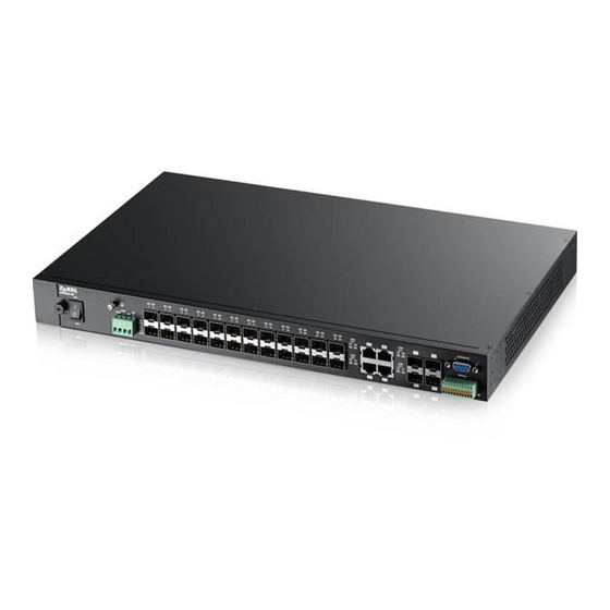
Figure 8 MGS3520-28F Front Panel: AC/DC Model Dual Personality Interfaces Power Switch Console Port LEDs Signal slot Power Connection SFP Slots Figure 9 MGS3520-50 Front Panel: AC/DC Model Dual Personality Interfaces Power Switch SFP slot Gigabit Ethernet Ports LEDs MGS3520 Series User’s Guide... -
Page 27: Console Port
• No flow control Connect the male 9-pin end of the console cable to the console port of the Switch. Connect the female end to a serial port (COM1, COM2 or other COM port) of your computer. MGS3520 Series User’s Guide... -
Page 28: Ethernet Ports
SFP Transceiver MultiSource Agreement (MSA). See the SFF committee’s INF-8074i specification Rev 1.0 for details. You can change transceivers while the Switch is operating. You can use different transceivers to connect to Ethernet switches with different types of fiber-optic or even copper cable connectors. MGS3520 Series User’s Guide... - Page 29 Use the following steps to remove a mini-GBIC transceiver (SFP module). Remove the fiber optic cables from the transceiver. Open the transceiver’s latch (latch styles vary). Pull the transceiver out of the slot. Figure 13 Removing the Fiber Optic Cables MGS3520 Series User’s Guide...
-
Page 30: Power Connector
Note: When installing the power wire, push it wire firmly into the terminal as deep as possible and make sure that no exposed (bare) wire can be seen or touched. Exposed power wire is dangerous. Use extreme care when connecting a DC power source to the device. MGS3520 Series User’s Guide... -
Page 31: Signal Slot
Repeat the process for the sensor’s other signal output wire. A total of four sensors may be connected to the Signal connector in this way using the remaining signal input pins. Insert the alarm connector into the Signal slot. MGS3520 Series User’s Guide... - Page 32 Figure 17 Daisy-chaining an External Alarm Sensor to Other Switches of the Same Model ..11 10 ..11 10 ..11 10 Pin Assignments MGS3520 Series User’s Guide...
-
Page 33: Leds
The link to a 100 Mbps Ethernet network is up. The link to an Ethernet network is down. Amber The Gigabit port is negotiating in full-duplex mode. The Gigabit port is negotiating in half-duplex mode. MGS3520 Series User’s Guide... -
Page 34: The Web Configurator
The login screen appears. The default username is admin and associated default password is 1234. The date and time display as shown if you have not configured a time server nor manually entered a time and date in the General Setup screen. MGS3520 Series User’s Guide... -
Page 35: The Web Configurator Layout
A - Click the menu items to open submenu links, and then click on a submenu link to open the screen in the main window. B, C, D, E - These are quick links which allow you to perform certain tasks no matter which screen you are currently working in. MGS3520 Series User’s Guide... - Page 36 The following table describes the links in the navigation panel. Table 5 Navigation Panel Links LINK DESCRIPTION Basic Settings System Info This link takes you to a screen that displays general system and hardware monitoring information. MGS3520 Series User’s Guide...
- Page 37 VLAN Stacking This link takes you to screens where you can activate and configure VLAN stacking. Multicast This link takes you to screen where you can configure various multicast features, IGMP snooping and create multicast VLANs. MGS3520 Series User’s Guide...
- Page 38 This link takes you to a screen where you can view the MAC address – IP address resolution table. Path MTU Table This link takes you to a screen where you can view the path MTU aging time, index, destination address, MTU, and expire settings. MGS3520 Series User’s Guide...
-
Page 39: Change Your Password
Click the Save link in the upper right hand corner of the web configurator to save your configuration to nonvolatile memory. Nonvolatile memory refers to the Switch’s storage that remains even if the Switch’s power is turned off. Note: Use the Save link when you are done with a configuration session. MGS3520 Series User’s Guide... -
Page 40: Switch Lockout
Disconnect and reconnect the Switch’s power to begin a session. When you reconnect the Switch’s power, you will see the initial screen. When you see the message “Press any key to enter Debug Mode within 3 seconds ...” press any key to enter debug mode. MGS3520 Series User’s Guide... -
Page 41: Logging Out Of The Web Configurator
Figure 22 Web Configurator: Logout Screen 4.8 Help The web configurator’s online help has descriptions of individual screens and some supplementary information. Click the Help link from a web configurator screen to view an online help description of that screen. MGS3520 Series User’s Guide... -
Page 42: Initial Setup Example
In this example, you want to configure port 1 as a member of VLAN 2. Figure 23 Initial Setup Network Example: VLAN Click Advanced Application > VLAN in the navigation panel and click the Static VLAN link. MGS3520 Series User’s Guide... -
Page 43: Setting Port Vid
VLAN group that the tag defines. In the example network, configure 2 as the port VID on port 1 so that any untagged frames received on that port get sent to VLAN 2. MGS3520 Series User’s Guide... -
Page 44: Configuring Switch Management Ip Address
The default management IP address of the Switch is 192.168.1.1. You can configure another IP address in a different subnet for management purposes. The following figure shows an example. Figure 25 Initial Setup Example: Management IP Address MGS3520 Series User’s Guide... - Page 45 VLAN ID you configure in the Static VLAN screen. Click Add to save your changes back to the run-time memory. Settings in the run-time memory are lost when the Switch’s power is turned off. MGS3520 Series User’s Guide...
-
Page 46: Tutorials
DHCP Server (A) 1 and 100 DHCP Client (B) 1 and 100 DHCP Client (C) 1 and 100 Access the Switch through http://192.168.1.1. Log into the Switch by entering the username (default: admin) and password (default: 1234). MGS3520 Series User’s Guide... - Page 47 7 to 100. This tags untagged incoming frames on ports 5, 6 and 7 with the tag 100. Go to Advanced Application > IP Source Guard > DHCP snooping > Configure, activate and specify VLAN 100 as the DHCP VLAN as shown. Click Apply. MGS3520 Series User’s Guide...
- Page 48 If you want to add more information in the DHCP request packets such as source VLAN ID or system name, you can also select the Option82 and Information fields in the entry. See Section 27.1.1.3 on page 238. MGS3520 Series User’s Guide...
-
Page 49: How To Use Dhcp Relay On The Switch
IP address (say 172.16.1.18) and gateway information to DHCP client A based on the system name, VLAN ID and port number in the DHCP request. Client A connects to the Switch’s port 2 in VLAN 102. MGS3520 Series User’s Guide... -
Page 50: Creating A Vlan
Name field and enter 102 in the VLAN Group ID field. Select Fixed to configure port 2 to be a permanent member of this VLAN. Clear the TX Tagging check box to set the Switch to remove VLAN tags before sending. MGS3520 Series User’s Guide... - Page 51 Enter 102 in the PVID field for port 2 to add a tag to incoming untagged frames received on that port so that the frames are forwarded to the VLAN group that the tag defines. 10 Click Apply to save your changes back to the run-time memory. MGS3520 Series User’s Guide...
-
Page 52: Configuring Dhcpv4 Relay
Select a pre-defined Option 82 Profile that includes the system name, VLAN ID and port number in the client DHCP requests (default2 in this example). Click Apply to save your changes back to the run-time memory. MGS3520 Series User’s Guide... -
Page 53: Troubleshooting
Switch B is connected to switch A. In this way, PPPoE server S can identify subscriber C and may apply different settings to it. Port 12 - Trusted Port 11 - Trusted Port 12 - Trusted Port 5 - Untrusted MGS3520 Series User’s Guide... -
Page 54: Configuring Switch A
Click Port on the top of the screen. Select Untrusted for port 5 and enter userC as Circuit-id and 00134900000A as Remote-id. Select Trusted for port 12 and then leave the other fields empty. Click Apply. MGS3520 Series User’s Guide... - Page 55 The Intermediate Agent screen appears. Click VLAN on the top of the screen. Enter 1 for both Start VID and End VID since both the Switch and PPPoE server are in VLAN 1 in this example. Click Apply. MGS3520 Series User’s Guide...
-
Page 56: Configuring Switch B
Switch to add these two strings to frames tagged with VLAN 1 and pass to the PPPoE server. Click Apply. 6.3.2 Configuring Switch B The example uses another MGS3520-28/28F as switch B. Click Advanced Application > PPPoE > Intermediate Agent. Select Active then click Apply. MGS3520 Series User’s Guide... - Page 57 Click Port on the top of the screen. Select Trusted for ports 11 and 12 and then click Apply. Then Click Intermediate Agent on the top of the screen. The Intermediate Agent screen appears. Click VLAN on the top of the screen. MGS3520 Series User’s Guide...
- Page 58 Then select Yes to enable PPPoE IA in VLAN 1 and also select Circuit-id and Remote-id to allow the Switch to add these two strings to frames tagged with VLAN 1 and pass to the PPPoE server. Click Apply. MGS3520 Series User’s Guide...
-
Page 59: How To Use Error Disable And Recovery On The Switch
Click Advanced Application > Errdisable > CPU Protection, select ARP as the reason, enter 100 as the rate limit (packets per second) for the first entry (port *) to apply the setting to all ports. Then click Apply. MGS3520 Series User’s Guide... - Page 60 Click Advanced Application > Errdisable > Errdisable Recovery, select Active and Timer Status for loopguard and ARP entries. Also enter 180 (180 seconds = 3 minutes) in the Interval field for both entries. Then click Apply. MGS3520 Series User’s Guide...
-
Page 61: How To Set Up A Guest Vlan
Access the web configurator through the Switch’s port which is not in VLAN 200. Go to Basic Setting > Switch Setup and set the VLAN type to 802.1Q. Click Apply to save the settings to the run-time memory. MGS3520 Series User’s Guide... - Page 62 Clear the TX Tagging check box to set the Switch to remove VLAN tags before sending frames out of these ports. Click Add to save the settings to the run-time memory. Settings in the run-time memory are lost when the Switch’s power is turned off. MGS3520 Series User’s Guide...
- Page 63 Enter 200 in the PVID field for ports 1, 2, 3 and 10 to add a tag to incoming untagged frames received on these ports so that the frames are forwarded to the VLAN group that the tag defines. 10 Click Apply to save your changes back to the run-time memory. MGS3520 Series User’s Guide...
-
Page 64: Enabling Ieee 802.1X Port Authentication
Click Advanced Application > Port Authentication and then the Click Here link for 802.1x. Select the first Active checkbox to enable 802.1x authentication on the Switch. Select the Active checkboxes for ports 1 to 8 to turn on 802.1x authentication on the selected ports. Click Apply. MGS3520 Series User’s Guide... -
Page 65: Enabling Guest Vlan
Set Host-mode to Multi-Secure to have the Switch authenticate each client that connects to one of these ports, and specify the maximum number of clients that the Switch will authenticate on each of these port (5 in this example). Click Apply. MGS3520 Series User’s Guide... -
Page 66: How To Do Port Isolation In A Vlan
IP routing domain for each individual port. Internet In this example, you put ports 2 to 4 and 25 in VLAN 123 and create a private VLAN rule for VLAN 123 to block traffic between ports 2, 3 and 4. MGS3520 Series User’s Guide... -
Page 67: Creating A Vlan
Clear the TX Tagging check box to set the Switch to remove VLAN tags before sending frames out of these ports. Click Add to save the settings to the run-time memory. Settings in the run-time memory are lost when the Switch’s power is turned off. MGS3520 Series User’s Guide... - Page 68 Enter 123 in the PVID field for ports 2, 3, 4 and 25 to add a tag to incoming untagged frames received on these ports so that the frames are forwarded to the VLAN group that the tag defines. 10 Click Apply to save your changes back to the run-time memory. MGS3520 Series User’s Guide...
-
Page 69: Creating A Private Vlan Rule
Follow the steps below to configure private VLAN for VLAN 123. Click Advanced Application > Private VLAN. In the Private VLAN screen, select Active. Enter a descriptive name (PrivateVLAN123 for example) in the Name field and enter 123 in the VLAN ID field. Click Add. MGS3520 Series User’s Guide... - Page 70 Ports 2, 3 and 4 in this VLAN will be added to the isolated port list automatically and cannot send traffic to each other. From port 2, 3, or 4, you should be able to access the device that attachs to port 25, such as a server or default gateway. MGS3520 Series User’s Guide...
-
Page 71: Technical Reference
Technical Reference... -
Page 72: System Status And Port Statistics
This identifies the Ethernet port. Click a port number to display the Port Details screen (refer to Figure 27 on page 74). Name This is the name you assigned to this port in the Basic Setting > Port Setup screen. MGS3520 Series User’s Guide... -
Page 73: Status: Port Details
7.2.1 Status: Port Details Click a number in the Port column in the Status screen to display individual port statistics. Use this screen to check status and detailed performance data about an individual port on the Switch. MGS3520 Series User’s Guide... - Page 74 This field shows if LACP is enabled on this port or not. TxPkts This field shows the number of transmitted frames on this port RxPkts This field shows the number of received frames on this port MGS3520 Series User’s Guide...
- Page 75 This field shows the number of packets (including bad packets) received that were between 256 and 511 octets in length. 512-1023 This field shows the number of packets (including bad packets) received that were between 512 and 1023 octets in length. MGS3520 Series User’s Guide...
- Page 76 1024 and 1518 octets in length. Giant This field shows the number of packets (including bad packets) received that were between 1519 octets and the maximum frame size. The maximum frame size varies depending on your switch model. MGS3520 Series User’s Guide...
-
Page 77: Basic Setting
In the navigation panel, click Basic Setting > System Info to display the screen as shown. You can check the firmware version number and monitor the Switch temperature, fan speeds and voltage in this screen. Figure 28 Basic Setting > System Info MGS3520 Series User’s Guide... - Page 78 This field displays the minimum voltage measured at this point. Threshold This field displays the percentage tolerance of the voltage with which the Switch still works. Status Normal indicates that the voltage is within an acceptable operating range at this point; otherwise Error is displayed. MGS3520 Series User’s Guide...
-
Page 79: General Setup
1970/1/1 at 0:0:0. NTP (RFC-1305) is similar to Time (RFC-868). None is the default value. Enter the time manually. Each time you turn on the Switch, the time and date will be reset to 1970-1-1 0:0. MGS3520 Series User’s Guide... -
Page 80: Introduction To Vlans
8.3 Introduction to VLANs A VLAN (Virtual Local Area Network) allows a physical network to be partitioned into multiple logical networks. Devices on a logical network belong to one group. A device can belong to more than one MGS3520 Series User’s Guide... -
Page 81: Switch Setup
Click Basic Setting > Switch Setup in the navigation panel to display the screen as shown. The VLAN setup screens change depending on whether you choose 802.1Q or Port Based in the VLAN Type field in this screen. Refer to the chapter on VLAN. Figure 30 Basic Setting > Switch Setup MGS3520 Series User’s Guide... - Page 82 This is for “spare bandwidth”. Level 1 This is typically used for non-critical “background” traffic such as bulk transfers that are allowed but that should not affect other applications and users. Level 0 Typically used for best-effort traffic. MGS3520 Series User’s Guide...
-
Page 83: Ip Setup
The factory default subnet mask is 255.255.255.0. You can configure up to 64 IP addresses which are used to access and manage the Switch from the ports belonging to the pre-defined VLAN(s). Note: You must configure a VLAN first. MGS3520 Series User’s Guide... - Page 84 IP Subnet Mask Enter the IP subnet mask of your Switch in dotted decimal notation for example 255.255.255.0. Default Gateway Enter the IP address of the default outgoing gateway in dotted decimal notation, for example 192.168.1.254. MGS3520 Series User’s Guide...
-
Page 85: Port Setup
Click Cancel to clear the selected check boxes in the Delete column. 8.6 Port Setup Use this screen to configure Switch port settings. Click Basic Setting > Port Setup in the navigation panel to display the configuration screen. MGS3520 Series User’s Guide... - Page 86 MGS3520 Series User’s Guide...
-
Page 87: Interface Setup
Use this screen to set IPv6 interfaces on which you can configure an IPv6 address to access and manage the Switch. Click Basic Setting > Interface Setup in the navigation panel to display the configuration screen. Figure 33 Basic Setting > Interface Setup MGS3520 Series User’s Guide... -
Page 88: Ipv6
This field displays the index number of an IPv6 interface. Click on an index number to view more interface details. Interface This is the name of the IPv6 interface you created. Active This field displays whether the IPv6 interface is activated or not. MGS3520 Series User’s Guide... -
Page 89: Ipv6 Interface Status
ICMPv6 Rate This field displays the maximum number of ICMPv6 error messages which are allowed to Limit Bucket transmit in a given time interval. If the bucket is full, subsequent error messages are Size suppressed. MGS3520 Series User’s Guide... - Page 90 This field displays the Switch’s global address which is assigned by the DHCPv6 server. Preferred This field displays how long (in seconds) that the global address remains preferred. Lifetime Valid This field displays how long (in seconds) that the global address is valid. Lifetime MGS3520 Series User’s Guide...
-
Page 91: Ipv6 Configuration
Click the link to go to a screen where you can create a static IPv6 neighbor entry in the Switch’s IPv6 neighbor table. DHCPv6 Client Setup Click the link to go to a screen where you can configure the Switch DHCP settings. MGS3520 Series User’s Guide... -
Page 92: Ipv6 Global Setup
Use this screen to turn on or off an IPv6 interface and enable stateless autoconfiguration on it. Click the link next to IPv6 Interface Setup in the IPv6 Configuration screen to display the screen as shown next. MGS3520 Series User’s Guide... -
Page 93: Ipv6 Link-Local Address Setup
A link-local unicast address has a predefined prefix of fe80::/10. Use this screen to configure the interface’s link-local address and default gateway. Click the link next to IPv6 Link-Local Address Setup in the IPv6 Configuration screen to display the screen as shown next. MGS3520 Series User’s Guide... -
Page 94: Ipv6 Global Address Setup
8.8.6 IPv6 Global Address Setup Use this screen to configure the interface’s IPv6 global address. Click the link next to IPv6 Global Address Setup in the IPv6 Configuration screen to display the screen as shown next. MGS3520 Series User’s Guide... -
Page 95: Ipv6 Neighbor Discovery Setup
8.8.7 IPv6 Neighbor Discovery Setup Use this screen to configure neighbor discovery settings for each interface. Click the link next to IPv6 Neighbor Discovery Setup in the IPv6 Configuration screen to display the screen as shown next. MGS3520 Series User’s Guide... -
Page 96: Ipv6 Neighbor Setup
Use this screen to create a static IPv6 neighbor entry in the Switch’s IPv6 neighbor table to store the neighbor information permanently. Click the link next to IPv6 Neighbor Setup in the IPv6 Configuration screen to display the screen as shown next. MGS3520 Series User’s Guide... - Page 97 Delete Check the entry(ies) that you want to remove in the Delete column and then click Delete to remove the selected entry(ies) from the summary table. Cancel Click Cancel to clear the Delete check boxes. MGS3520 Series User’s Guide...
-
Page 98: Dhcpv6 Client Setup
This field displays whether the Switch obtains a non-temporary IP address from the DHCPv6 server. Rapid-Commit This field displays whether the Switch obtains information from the DHCPv6 server by a rapid two-message exchange. This field displays whether the Switch obtains DNS server IPv6 addresses from the DHCPv6 server. MGS3520 Series User’s Guide... - Page 99 This field displays whether the Switch obtains a list of domain names from the DHCP server. Information Refresh This field displays the time interval (in seconds) at which the Switch exchanges other Minimum configuration information with a DHCPv6 server again. MGS3520 Series User’s Guide...
-
Page 100: Vlan
A broadcast frame (or a multicast frame for a multicast group that is known by the system) is duplicated only on ports that are members of the VID (except the ingress port itself), thus confining the broadcast to a specific domain. MGS3520 Series User’s Guide... -
Page 101: Automatic Vlan Registration
You may choose to accept both tagged and untagged incoming Type frames, just tagged incoming frames or just untagged incoming frames on a port. Ingress filtering If set, the Switch discards incoming frames for VLANs that do not have this port as a member. MGS3520 Series User’s Guide... -
Page 102: Port Vlan Trunking
• sent to a group whether it has a VLAN tag or not. • blocked from a VLAN group regardless of its VLAN tag. You can also tag all outgoing frames (that were previously untagged) from a port with the specified VID. MGS3520 Series User’s Guide... -
Page 103: Vlan Status
Use this screen to view detailed port settings and status of the VLAN group. See Section 9.1 on page 100 for more information on static VLAN. Click on an index number in the VLAN Status screen to display VLAN details. MGS3520 Series User’s Guide... -
Page 104: Configure A Static Vlan
Use this screen to configure and view 802.1Q VLAN parameters for the Switch. See Section 9.1 on page 100 for more information on static VLAN. To configure a static VLAN, click Static VLAN in the VLAN Status screen to display the screen as shown next. MGS3520 Series User’s Guide... - Page 105 Use this row only if you want to make some settings the same for all ports. Use this row first to set the common settings and then make adjustments on a port-by-port basis. Note: Changes in this row are copied to all the ports as soon as you make them. MGS3520 Series User’s Guide...
-
Page 106: Configure Vlan Port Settings
Use the VLAN Port Setting screen to configure the static VLAN (IEEE 802.1Q) settings on a port. Section 9.1 on page 100 for more information on static VLAN. Click the VLAN Port Setting link in the VLAN Status screen. Figure 49 Advanced Application > VLAN > VLAN Port Setting MGS3520 Series User’s Guide... -
Page 107: Subnet Based Vlans
IP subnet. For example, an ISP (Internet Service Provider) may divide different types of services it provides to customers into different IP subnets. Traffic for voice services is designated for IP subnet MGS3520 Series User’s Guide... -
Page 108: Configuring Subnet Based Vlan
Click Subnet Based VLAN in the VLAN Port Setting screen to display the configuration screen as shown. Note: Subnet based VLAN applies to un-tagged packets and is applicable only when you use IEEE 802.1Q tagged VLAN. MGS3520 Series User’s Guide... - Page 109 Save link on the top navigation panel to save your changes to the non-volatile memory when you are done configuring. Cancel Click Cancel to begin configuring this screen afresh. MGS3520 Series User’s Guide...
-
Page 110: Protocol Based Vlans
Apple Talk traffic from port 6 and 7 will be in another group and have higher priority than ARP traffic when they go through the uplink port to a backbone switch C. Figure 52 Protocol Based VLAN Application Example MGS3520 Series User’s Guide... -
Page 111: Configuring Protocol Based Vlan
Cancel Click Cancel to begin configuring this screen afresh. Index This is the index number identifying this protocol based VLAN. Click on any of these numbers to edit an existing protocol based VLAN. MGS3520 Series User’s Guide... -
Page 112: Create An Ip-Based Vlan Example
Type the VLAN ID of an existing VLAN. In our example we already created a static VLAN with an ID of 5. Type 5. Leave the priority set to 0 and click Add. Figure 54 Protocol Based VLAN Configuration Example EXAMPLE To add more ports to this protocol based VLAN. MGS3520 Series User’s Guide... -
Page 113: Mac Based Vlan
Table 33 Advanced Application > VLAN > VLAN Port Setting > MAC Based VLAN LABEL DESCRIPTION Active Check this box to activate this MAC based VLAN. Name Type a name up to 32 alpha numeric characters for the MAC-based VLAN entry. MGS3520 Series User’s Guide... -
Page 114: Vlan Mac Learning
Click Cancel to clear the check boxes. 9.9 VLAN MAC Learning Use this screen to set the MAC address learning limit on per-port and per-VLAN basis. Click VLAN MAC Learning in the VLAN Status screen to display the screen as shown next. MGS3520 Series User’s Guide... - Page 115 To specify a port, select the second choice and enter the number of the port to which this rule is applied. MAC Learning Select this option to enable the MAC address learning limit in this rule. MGS3520 Series User’s Guide...
-
Page 116: Port-Based Vlan Setup
Note: In screens (such as IP Setup and Filtering) that require a VID, you must enter 1 as the VID. The port-based VLAN setup screen is shown next. The CPU management port forms a VLAN with all Ethernet ports. MGS3520 Series User’s Guide... -
Page 117: Configure A Port-Based Vlan
The following screen shows users on a port-based, all-connected VLAN configuration. Figure 57 Advanced Application > VLAN > Port Based VLAN Setup (All Connected) The following screen shows users on a port-based, port-isolated VLAN configuration. MGS3520 Series User’s Guide... - Page 118 Chapter 9 VLAN Figure 58 Advanced Application > VLAN: Port Based VLAN Setup (Port Isolation) MGS3520 Series User’s Guide...
- Page 119 Save link on the top navigation panel to save your changes to the non-volatile memory when you are done configuring. Cancel Click Cancel to begin configuring this screen afresh. MGS3520 Series User’s Guide...
-
Page 120: Static Mac Forward Setup
Chapter 19 on page 171 for more information on port security. Click Advanced Applications > Static MAC Forwarding in the navigation panel to display the configuration screen as shown. Figure 59 Advanced Application > Static MAC Forwarding MGS3520 Series User’s Guide... - Page 121 This field displays the port where the MAC address shown in the next field will be forwarded. Delete Click Delete to remove the selected entry from the summary table. Cancel Click Cancel to clear the Delete check boxes. MGS3520 Series User’s Guide...
-
Page 122: Static Multicast Forward Setup
3. Figure 62 shows frames being forwarded to ports 2 and 3 within VLAN group 4. Figure 60 No Static Multicast Forwarding Figure 61 Static Multicast Forwarding to A Single Port MGS3520 Series User’s Guide... -
Page 123: Configuring Static Multicast Forwarding
Enter a multicast MAC address which identifies the multicast group. The last binary bit of the first octet pair in a multicast MAC address must be 1. For example, the first octet pair 00000001 is 01 and 00000011 is 03 in hexadecimal, so 01:00:5e:00:00:0A and 03:00:5e:00:00:27 are valid multicast MAC addresses. MGS3520 Series User’s Guide... - Page 124 This field displays the port(s) within a identified VLAN group to which frames containing the specified multicast MAC address will be forwarded. Delete Click Delete to remove the selected entry from the summary table. Cancel Click Cancel to clear the Delete check boxes. MGS3520 Series User’s Guide...
-
Page 125: Filtering
Select Discard destination to drop frames to the destination MAC address (specified in the MAC address). The Switch can still receive frames originating from the MAC address. Select Discard source and Discard destination to block traffic to/from the MAC address specified in the MAC field. MGS3520 Series User’s Guide... - Page 126 This field displays the VLAN group identification number. Delete Check the rule(s) that you want to remove in the Delete column and then click the Delete button. Cancel Click Cancel to clear the selected checkbox(es) in the Delete column. MGS3520 Series User’s Guide...
-
Page 127: Spanning Tree Protocol
The slower the media, the higher the cost. Table 39 STP Path Costs DEFAULT VALUE DEFAULT VALUE LINK SPEED ALLOWED RANGE (SHORT) (LONG) Path Cost 10Mbps 2,000,000 1 to 200,000,000 Path Cost 100Mbps 200,000 1 to 200,000,000 MGS3520 Series User’s Guide... -
Page 128: How Stp Works
MRSTP (Multiple RSTP) is ZyXEL’s proprietary feature that is compatible with RSTP and STP. With MRSTP, you can have more than one spanning tree on your Switch and assign port(s) to each tree. Each spanning tree operates independently with its own bridge information. MGS3520 Series User’s Guide... -
Page 129: Multiple Stp
The following figure shows a network example where two VLANs are configured on the two switches. If the switches are using STP or RSTP, the link for VLAN 2 will be blocked as STP and RSTP allow only one link in the network and block the redundant link. MGS3520 Series User’s Guide... -
Page 130: Mst Region
Devices that belong to the same MST region are configured to have the same MSTP configuration identification settings. These include the following parameters: • Name of the MST region • Revision level as the unique number for the MST region • VLAN-to-MST Instance mapping MGS3520 Series User’s Guide... - Page 131 MST instance are members of the CIST. In an MSTP-enabled network, there is only one CIST that runs between MST regions and single spanning tree devices. A network may contain multiple MST regions and other network segments running RSTP. Figure 69 MSTP and Legacy RSTP Network Example MGS3520 Series User’s Guide...
-
Page 132: Spanning Tree Protocol Status Screen
Use the Spanning Tree Configuration screen to activate one of the STP modes on the Switch. Click Configuration in the Advanced Application > Spanning Tree Protocol. Figure 71 Advanced Application > Spanning Tree Protocol > Configuration MGS3520 Series User’s Guide... -
Page 133: Configure Rapid Spanning Tree Protocol
Click Cancel to begin configuring this screen afresh. 13.4 Configure Rapid Spanning Tree Protocol Use this screen to configure RSTP settings, see Section 13.1 on page 127 for more information on RSTP. Click RSTP in the Advanced Application > Spanning Tree Protocol screen. MGS3520 Series User’s Guide... - Page 134 Bridge Priority determines the root bridge, which in turn determines Hello Time, Max Age and Forwarding Delay. Hello Time This is the time interval in seconds between BPDU (Bridge Protocol Data Units) configuration message generations by the root switch. The allowed range is 1 to 10 seconds. MGS3520 Series User’s Guide...
- Page 135 Save link on the top navigation panel to save your changes to the non-volatile memory when you are done configuring. Cancel Click Cancel to begin configuring this screen afresh. MGS3520 Series User’s Guide...
-
Page 136: Rapid Spanning Tree Protocol Status
Spanning Tree. Topology Changed This is the number of times the spanning tree has been reconfigured. Times Time Since Last This is the time since the spanning tree was last reconfigured. Change MGS3520 Series User’s Guide... -
Page 137: Configure Multiple Rapid Spanning Tree Protocol
Bridge Priority determines the root bridge, which in turn determines Hello Time, Max Age and Forwarding Delay. Hello Time This is the time interval in seconds between BPDU (Bridge Protocol Data Units) configuration message generations by the root switch. The allowed range is 1 to 10 seconds. MGS3520 Series User’s Guide... - Page 138 Save link on the top navigation panel to save your changes to the non-volatile memory when you are done configuring. Cancel Click Cancel to begin configuring this screen afresh. MGS3520 Series User’s Guide...
-
Page 139: Multiple Rapid Spanning Tree Protocol Status
Spanning Tree. Topology Changed This is the number of times the spanning tree has been reconfigured. Times Time Since Last This is the time since the spanning tree was last reconfigured. Change MGS3520 Series User’s Guide... -
Page 140: Configure Multiple Spanning Tree Protocol
13.8 Configure Multiple Spanning Tree Protocol To configure MSTP, click MSTP in the Advanced Application > Spanning Tree Protocol screen. Section 13.1.5 on page 129 for more information on MSTP. Figure 76 Advanced Application > Spanning Tree Protocol > MSTP MGS3520 Series User’s Guide... - Page 141 Switch will be chosen as the root bridge within the spanning tree instance. Enter priority values between 0 and 61440 in increments of 4096 (thus valid values are 4096, 8192, 12288, 16384, 20480, 24576, 28672, 32768, 36864, 40960, 45056, 49152, 53248, 57344 and 61440). MGS3520 Series User’s Guide...
-
Page 142: Multiple Spanning Tree Protocol Port Configuration
Check the rule(s) that you want to remove in the Delete column and then click the Delete button. Cancel Click Cancel to begin configuring this screen afresh. 13.8.1 Multiple Spanning Tree Protocol Port Configuration To configure MSTP ports, click Port in the Advanced Application > Spanning Tree Protocol > MSTP screen. MGS3520 Series User’s Guide... - Page 143 Save link on the top navigation panel to save your changes to the non-volatile memory when you are done configuring. Cancel Click Cancel to begin configuring this screen afresh. MGS3520 Series User’s Guide...
-
Page 144: Multiple Spanning Tree Protocol Status
This is the time (in seconds) the root switch will wait before changing states (that is, (second) listening to learning to forwarding). Cost to Bridge This is the path cost from the root port on this Switch to the root switch. MGS3520 Series User’s Guide... - Page 145 This is the path cost from the root port in this MST instance to the regional root switch. Port ID This is the priority and number of the port on the Switch through which this Switch must communicate with the root of the MST instance. MGS3520 Series User’s Guide...
-
Page 146: Bandwidth Control
Bandwidth control means defining a maximum allowable bandwidth for incoming and/or out-going traffic flows on a port. 14.2 Bandwidth Control Setup Click Advanced Application > Bandwidth Control in the navigation panel to bring up the screen as shown next. Figure 79 Advanced Application > Bandwidth Control MGS3520 Series User’s Guide... - Page 147 Save link on the top navigation panel to save your changes to the non-volatile memory when you are done configuring. Cancel Click Cancel to begin configuring this screen afresh. MGS3520 Series User’s Guide...
-
Page 148: Broadcast Storm Control
You can specify limits for each packet type on each port. Click Advanced Application > Broadcast Storm Control in the navigation panel to display the screen as shown next. Figure 80 Advanced Application > Broadcast Storm Control MGS3520 Series User’s Guide... - Page 149 Save link on the top navigation panel to save your changes to the non-volatile memory when you are done configuring. Cancel Click Cancel to begin configuring this screen afresh. MGS3520 Series User’s Guide...
-
Page 150: Mirroring
Note: If the Switch is not acting as a source or destination device in remote port mirroring, you need to enable port VLAN trunking to allow traffic belonging to the specific RMirror VLAN to pass through it. Alternatively, you can configure a VLAN group for the mirrored traffic. MGS3520 Series User’s Guide... - Page 151 But it cannot be the monitor port in local port mirroring. Table 52 Port Rules between Remote and Local Port Mirroring RMirror Source Mirrored Port Source Mirroring Destination Monitor Port Port Mirrored Local Port Port Monitor Mirroring Port MGS3520 Series User’s Guide...
-
Page 152: Local Port Mirroring Screen
Note: Changes in this row are copied to all the ports as soon as you make them. Mirrored Select this option to mirror the traffic on a port. Direction Specify the direction of the traffic to mirror by selecting from the drop-down list box. Choices are Egress (outgoing), Ingress (incoming) and Both. MGS3520 Series User’s Guide... -
Page 153: Rmirror-Source Screen
Use this screen to set the RMirror VLAN ID, configure the mirroring port and specify the traffic flow to be copied when the Switch is the source device in remote port mirroring. Click the RMirror-Source link in the Mirroring screen. The following screen opens. Figure 82 Advanced Application > Mirroring > RMirror-Source MGS3520 Series User’s Guide... -
Page 154: Rmirror-Destination Screen
Use this screen to specify the RMirror VLAN ID and configure the monitor port when the Switch is the destination device in remote port mirroring. Click the RMirror-Destination link in the Mirroring screen. The following screen opens. MGS3520 Series User’s Guide... - Page 155 Save link on the top navigation panel to save your changes to the nonvolatile memory when you are done configuring. Cancel Click Cancel to begin configuring this screen afresh. MGS3520 Series User’s Guide...
-
Page 156: Link Aggregation
• You must connect all ports point-to-point to the same Ethernet switch and configure the ports for LACP trunking. • LACP only works on full-duplex links. • All ports in the same trunk group must have the same media type, speed, duplex mode and flow control settings. MGS3520 Series User’s Guide... -
Page 157: Link Aggregation Id
These are the ports that are currently transmitting data as one logical link in this trunk Ports group. Port Priority and Port Number are 0 as it is the aggregator ID for the trunk group, not the individual port. MGS3520 Series User’s Guide... -
Page 158: Link Aggregation Setting
LACP - if the ports are configured to join a trunk group via LACP. 17.4 Link Aggregation Setting Click Advanced Application > Link Aggregation > Link Aggregation Setting to display the screen shown next. See Section 17.1 on page 156 for more information on link aggregation. MGS3520 Series User’s Guide... - Page 159 Select src-ip to distribute traffic based on the packet’s source IP address. Select dst-ip to distribute traffic based on the packet’s destination IP address. Select src-dst-ip to distribute traffic based on a combination of the packet’s source and destination IP addresses. MGS3520 Series User’s Guide...
-
Page 160: Link Aggregation Control Protocol
Click in the Advanced Application > Link Aggregation > Link Aggregation Setting > LACP to display the screen shown next. See Section 17.2 on page 156 for more information on dynamic link aggregation. Figure 86 Advanced Application > Link Aggregation > Link Aggregation Setting > LACP MGS3520 Series User’s Guide... -
Page 161: Static Trunking Example
Make your physical connections - make sure that the ports that you want to belong to the trunk group are connected to the same destination. The following figure shows ports 2-5 on switch A connected to switch B. MGS3520 Series User’s Guide... - Page 162 Click Apply when you are done. Figure 88 Trunking Example - Configuration Screen EXAMPLE Your trunk group 1 (T1) configuration is now complete. MGS3520 Series User’s Guide...
-
Page 163: Port Authentication
At the time of writing, IEEE 802.1x is not supported by all operating systems. See your operating system documentation. If your operating system does not support 802.1x, then you may need to install 802.1x client software. MGS3520 Series User’s Guide... -
Page 164: Mac Authentication
Switch does not prompt the client for login credentials. The login credentials are based on the source MAC address of the client connecting to a port on the Switch along with a password configured specifically for MAC authentication on the Switch. MGS3520 Series User’s Guide... -
Page 165: Port Authentication Configuration
Select a port authentication method in the screen that appears. Figure 91 Advanced Application > Port Authentication 18.2.1 Activate IEEE 802.1x Security Use this screen to activate IEEE 802.1x security. In the Port Authentication screen click 802.1x to display the configuration screen as shown. MGS3520 Series User’s Guide... - Page 166 Specify if a subscriber has to periodically re-enter his or her username and password to stay connected to the port. Reauth-period Specify the length of time required to pass before a client has to re-enter his or her username and password to stay connected to the port. MGS3520 Series User’s Guide...
-
Page 167: Guest Vlan
Figure 93 Guest VLAN Example VLAN 100 VLAN 102 Internet Use this screen to enable and assign a guest VLAN to a port. In the Port Authentication > 802.1x screen click Guest Vlan to display the configuration screen as shown. MGS3520 Series User’s Guide... - Page 168 Select Multi-Secure to authenticate each user that connects to this port. Multi-Secure If you set Host-mode to Multi-Secure, specify the maximum number of users (between 1 and 5) that the Switch will authenticate on this port. MGS3520 Series User’s Guide...
-
Page 169: Activate Mac Authentication
If you leave this field blank, then only the MAC address of the client is forwarded to the RADIUS server. Password Type the password the Switch sends along with the MAC address of a client for authentication with the RADIUS server. You can enter up to 32 printable ASCII characters. MGS3520 Series User’s Guide... - Page 170 Save link on the top navigation panel to save your changes to the non-volatile memory when you are done configuring. Cancel Click Cancel to begin configuring this screen afresh. MGS3520 Series User’s Guide...
-
Page 171: Port Security
By default, MAC address learning is still enabled even though the port security is not activated. 19.2 Port Security Setup Click Advanced Application > Port Security in the navigation panel to display the screen as shown. MGS3520 Series User’s Guide... - Page 172 MAC addresses that may be learned on a port is reached. Click the Errdisable link to go to the Errdisable Recovery screen where you can set the port to become active automatically after a specified time interval. Port This field displays a port number. MGS3520 Series User’s Guide...
- Page 173 Save link on the top navigation panel to save your changes to the non-volatile memory when you are done configuring. Cancel Click Cancel to begin configuring this screen afresh. MGS3520 Series User’s Guide...
-
Page 174: Range Profile
Figure 97 Advanced Application > Range Profile 20.3 VLAN Range Profile Use this screen to view, manage and create VLAN range profiles. In the Range Profile screen, click VLAN Range to display the screen as shown. MGS3520 Series User’s Guide... -
Page 175: Port Range Profile
Click Cancel to begin configuring this screen afresh. 20.4 Port Range Profile Use this screen to view, manage and create port range profiles. In the Range Profile screen, click Port Range to display the screen as shown. MGS3520 Series User’s Guide... -
Page 176: Ip Address Range Profile
Click Cancel to begin configuring this screen afresh. 20.5 IP Address Range Profile Use this screen to view, manage and create IP address range profiles. In the Range Profile screen, click IP Address Range to display the screen as shown. MGS3520 Series User’s Guide... -
Page 177: Socket-Port Range Profile
Click Cancel to begin configuring this screen afresh. 20.6 Socket-Port Range Profile Use this screen to view, manage and create socket port range profiles. In the Range Profile screen, click Socket-port Range to display the screen as shown. MGS3520 Series User’s Guide... - Page 178 This field displays whether this profile is in use by a feature, such as classifier. Delete Check the profile(s) that you want to remove in the Delete column and then click the Delete button. Cancel Click Cancel to begin configuring this screen afresh. MGS3520 Series User’s Guide...
-
Page 179: Classifier
(or policy) to act upon the traffic that matches the rules. To configure policy rules, refer to Chapter 22 on page 185. Click Advanced Application > Classifier in the navigation panel to display the configuration screen as shown. MGS3520 Series User’s Guide... - Page 180 Table 69 Advanced Application > Classifier LABEL DESCRIPTION Active Select this option to enable this rule. Name Enter a descriptive name for this rule for identifying purposes. Layer 2 Specify the fields below to configure a layer-2 classifier. MGS3520 Series User’s Guide...
- Page 181 The Next Header field is similar to the IPv4 Protocol field. The IPv6 protocol number ranges from 1 to 255. You may select Establish Only for TCP protocol type. This means that the Switch will identify packets that initiate or acknowledge (establish) TCP connections. MGS3520 Series User’s Guide...
-
Page 182: Viewing And Editing Classifier Configuration
Classifier screen. To change the settings of a rule, click a number in the Index field. Note: When two rules conflict with each other, a higher layer rule has priority over a lower layer rule. Figure 103 Advanced Application > Classifier: Summary Table MGS3520 Series User’s Guide... -
Page 183: Classifier Example
Table 72 Common IP Ports PORT NUMBER PORT NAME Telnet SMTP HTTP POP3 21.4 Classifier Example The following screen shows an example of configuring a classifier that identifies all traffic from MAC address 00:50:ba:ad:4f:81 on port 2. MGS3520 Series User’s Guide... - Page 184 Figure 104 Classifier: Example EXAMPLE After you have configured a classifier, you can configure a policy to define action(s) on the classified traffic flow. See Chapter 22 on page 185 for information on configuring a policy rule. MGS3520 Series User’s Guide...
-
Page 185: Policy Rule
Resources can then be allocated according to the DSCP values and the configured policies. 22.2 Configuring Policy Rules You must first configure a classifier in the Classifier screen. Refer to Section 21.2 on page 179 more information. MGS3520 Series User’s Guide... - Page 186 [SHIFT] and select the choices at the same time. Parameters Set the fields below for this policy. You only have to set the field(s) that is related to the action(s) you configure in the Action field. MGS3520 Series User’s Guide...
-
Page 187: Viewing And Editing Policy Configuration
To view a summary of the classifier configuration, scroll down to the summary table at the bottom of the Policy screen. To change the settings of a rule, click a number in the Index field. Figure 106 Advanced Application > Policy Rule: Summary Table MGS3520 Series User’s Guide... -
Page 188: Policy Example
Click Cancel to clear the Delete check boxes. 22.4 Policy Example The figure below shows an example Policy screen where you configure a policy to limit bandwidth on a traffic flow classified using the Example classifier (refer to Section 21.4 on page 183). MGS3520 Series User’s Guide... - Page 189 Chapter 22 Policy Rule Figure 107 Policy Example EXAMPLE MGS3520 Series User’s Guide...
-
Page 190: Queuing Method
The weights range from 1 to 15 and the actual guaranteed bandwidth is calculated as follows: (Weight -1) x 10 KB If the weight setting is 5, the actual quantum guaranteed to the associated queue would be as follows: x 10KB = 160 KB MGS3520 Series User’s Guide... -
Page 191: Weighted Round Robin Scheduling (Wrr)
This queuing mechanism is highly efficient in that it divides any available bandwidth across the different traffic queues and returns to queues that have not yet emptied. 23.2 Configuring Queuing Click Advanced Application > Queuing Method in the navigation panel. Figure 108 Advanced Application > Queuing Method MGS3520 Series User’s Guide... - Page 192 Save link on the top navigation panel to save your changes to the non-volatile memory when you are done configuring. Cancel Click Cancel to begin configuring this screen afresh. MGS3520 Series User’s Guide...
-
Page 193: Vlan Stacking
VLAN group. The service provider can separate these two VLANs within its network by adding tag 37 to distinguish customer A and tag 48 to distinguish customer B at edge device 1 and then stripping those tags at edge device 2 as the data frames leave the network. MGS3520 Series User’s Guide... -
Page 194: Vlan Stacking Port Roles
Note: Static VLAN Tx Tagging MUST be enabled on a port where you choose Tunnel Port. 24.3 VLAN Tag Format A VLAN tag (service provider VLAN stacking or customer IEEE 802.1Q) consists of the following three fields. Table 76 VLAN Tag Format Type Priority MGS3520 Series User’s Guide... -
Page 195: Frame Format
Length and type of Ethernet frame (SP)TPID (Service Provider) Tag Protocol IDentifier Data Frame data VLAN ID Frame Check Sequence 24.4 Configuring VLAN Stacking Click Advanced Applications > VLAN Stacking to display the screen as shown. MGS3520 Series User’s Guide... - Page 196 Save link on the top navigation panel to save your changes to the non-volatile memory when you are done configuring. Cancel Click Cancel to begin configuring this screen afresh. MGS3520 Series User’s Guide...
-
Page 197: Port-Based Q-In-Q
Save link on the top navigation panel to save your changes to the non-volatile memory when you are done configuring. Cancel Click Cancel to begin configuring this screen afresh. MGS3520 Series User’s Guide... -
Page 198: Selective Q-In-Q
Save link on the top navigation panel to save your changes to the non-volatile memory when you are done configuring. Cancel Click Cancel to begin configuring this screen afresh. MGS3520 Series User’s Guide... - Page 199 This is the service provider’s priority level in the packets. Delete Check the rule(s) that you want to remove in the Delete column and then click the Delete button. Cancel Click Cancel to clear the Delete check boxes. MGS3520 Series User’s Guide...
-
Page 200: Multicast
The Switch forwards multicast traffic destined for multicast groups (that it has learned from IGMP snooping or that you have manually configured) to ports that are members of that group. IGMP snooping generates no additional network traffic, allowing you to significantly reduce multicast traffic passing through your Switch. MGS3520 Series User’s Guide... -
Page 201: Igmp Snooping And Vlans
The connection between ports 8 and 9 is blocked by STP to break the loop. If there is one query from a router (X) or MLD Done or Report message from any upstream port, it will be broadcast to all connected upstream ports. Query Report Done MGS3520 Series User’s Guide... -
Page 202: Mld Messages
Click Advanced Applications > Multicast > IPv4 Multicast to display the screen as shown. This screen shows the IPv4 multicast group information. See Section 25.1 on page 200 for more information on multicasting. Figure 114 Advanced Application > Multicast > IPv4 Multicast MGS3520 Series User’s Guide... -
Page 203: Igmp Snooping
Click the IGMP Snooping link in the Advanced Application > Multicast > IPv4 Multicast screen to display the screen as shown. See Section 25.1 on page 200 for more information on multicasting. Figure 115 Advanced Application > Multicast > IPv4 Multicast > IGMP Snooping MGS3520 Series User’s Guide... - Page 204 Select this option to set the Switch to remove this port from the multicast tree when an IGMP version 2 leave message is received on this port. Select this option if there is only one host connected to this port. MGS3520 Series User’s Guide...
- Page 205 Select Edge to stop the Switch from using the port as an IGMP query port. The Switch will not keep any record of an IGMP router being connected to this port. The Switch does not forward IGMP join or leave packets to this port. MGS3520 Series User’s Guide...
-
Page 206: Igmp Snooping Vlan
Click Apply to save your changes to the Switch’s run-time memory. The Switch loses these changes if it is turned off or loses power, so use the Save link on the top navigation panel to save your changes to the non-volatile memory when you are done configuring. MGS3520 Series User’s Guide... -
Page 207: Igmp Filtering Profile
Click Advanced Application > Multicast > IPv4 Multicast in the navigation panel. Click the IGMP Snooping link and then the IGMP Filtering Profile link to display the screen as shown. Figure 117 Advanced Application > Multicast > IPv4 Multicast > IGMP Snooping > IGMP Filtering Profile MGS3520 Series User’s Guide... -
Page 208: Ipv6 Multicast Status
Table 87 Advanced Application > Multicast > IPv6 Multicast LABEL DESCRIPTION Index This is the index number of the entry. This field displays the multicast VLAN ID. Port This field displays the port number that belongs to the multicast group. MGS3520 Series User’s Guide... -
Page 209: Mld Snooping-Proxy
25.4.2 MLD Snooping-proxy VLAN Click the VLAN link in the Advanced Application > Multicast > IPv6 Multicast > MLD Snooping-proxy screen to display the screen as shown. See Section 25.1 on page 200 for more information on multicasting. MGS3520 Series User’s Guide... - Page 210 This value should be exactly the same as what’s configured in the connected multicast router. This value is used to calculate the amount of time an MLD snooping membership entry (learned only on the upstream port) can remain in the forwarding table. MGS3520 Series User’s Guide...
-
Page 211: Mld Snooping-Proxy Vlan Port Role Setting
Click the Port Role Setting link in the Advanced Application > Multicast > IPv6 Multicast > MLD Snooping-proxy > VLAN screen to display the screen as shown. See Section 25.1 on page for more information on multicasting. MGS3520 Series User’s Guide... - Page 212 Report or Done messages when receiving queries from a multicast router. Otherwise, select None if the port is not joining a multicast group or does not belong to this VLAN. MGS3520 Series User’s Guide...
-
Page 213: Mld Snooping-Proxy Filtering
25.4.4 MLD Snooping-proxy Filtering Use this screen to configure the Switch’s MLD filtering settings. Click the Filtering link in the Advanced Application > Multicast > IPv6 Multicast > MLD Snooping-proxy screen to display the screen as shown. MGS3520 Series User’s Guide... - Page 214 Save link on the top navigation panel to save your changes to the non-volatile memory when you are done configuring. Cancel Click Cancel to reset the fields to your previous configuration. MGS3520 Series User’s Guide...
-
Page 215: Mld Snooping-Proxy Filtering Profile
This field displays the end of the multicast IPv6 address range. Delete Check the profile(s) that you want to remove in the Delete column, then click the Delete button. Cancel Click Cancel to clear the check boxes. MGS3520 Series User’s Guide... -
Page 216: Mvr Overview
The following figure shows a multicast television example where a subscriber device (such as a computer) in VLAN 1 receives multicast traffic from the streaming media server, S, via the Switch. Multiple subscriber devices can connect through a port configured as the receiver on the Switch. MGS3520 Series User’s Guide... -
Page 217: General Mvr Configuration
Note: You can create up to five multicast VLANs and up to 256 multicast rules on the Switch. Note: Your Switch automatically creates a static VLAN (with the same VID) when you create a multicast VLAN in this screen. MGS3520 Series User’s Guide... - Page 218 Select Dynamic to send IGMP reports to all MVR source ports in the multicast VLAN. Select Compatible to set the Switch not to send IGMP reports. Port This field displays the port number on the Switch. MGS3520 Series User’s Guide...
-
Page 219: Mvr Group Configuration
Configure MVR IP multicast group address(es) in the Group Configuration screen. Click Group Configuration in the MVR screen. Note: A port can belong to more than one multicast VLAN. However, IP multicast group addresses in different multicast VLANs cannot overlap. MGS3520 Series User’s Guide... - Page 220 Select the entry(ies) that you want to remove in the Delete column, then click the Delete button to remove the selected entry(ies) from the table. If you delete a multicast VLAN, all multicast groups in this VLAN will also be removed. Cancel Select Cancel to clear the checkbox(es) in the table. MGS3520 Series User’s Guide...
-
Page 221: Mvr Configuration Example
To set the Switch to forward the multicast group traffic to the subscribers, configure multicast group settings in the Group Configuration screen. The following figure shows an example where two multicast groups (News and Movie) are configured for the multicast VLAN 200. MGS3520 Series User’s Guide... - Page 222 Chapter 25 Multicast Figure 130 MVR Group Configuration Example-1 EXAMPLE Figure 131 MVR Group Configuration Example-2 EXAMPLE MGS3520 Series User’s Guide...
-
Page 223: Aaa
By storing user profiles locally on the Switch, your Switch is able to authenticate and authorize users without interacting with a network AAA server. However, there is a limit on the number of users you may authenticate in this way (See Chapter 42 on page 348). MGS3520 Series User’s Guide... -
Page 224: Radius And Tacacs
RADIUS servers and Section 26.3 on page 232 for RADIUS attributes utilized by the authentication and accounting features on the Switch. Click on the RADIUS Server Setup link in the AAA screen to view the screen as shown. MGS3520 Series User’s Guide... - Page 225 RADIUS server and the Switch. This key is not sent over the network. This key must be the same on the external RADIUS server and the Switch. Note that as you type a password, the screen displays an asterisk (*) for each character you type. MGS3520 Series User’s Guide...
-
Page 226: Tacacs+ Server Setup
Use this screen to configure your TACACS+ server settings. See Section 26.1.2 on page 224 more information on TACACS+ servers. Click on the TACACS+ Server Setup link in the Authentication and Accounting screen to view the screen as shown. MGS3520 Series User’s Guide... - Page 227 TACACS+ server and the Switch. This key is not sent over the network. This key must be the same on the external TACACS+ server and the Switch. Note that as you type a password, the screen displays an asterisk (*) for each character you type. MGS3520 Series User’s Guide...
-
Page 228: Aaa Setup
Click Cancel to begin configuring this screen afresh. 26.2.3 AAA Setup Use this screen to configure authentication, authorization and accounting settings on the Switch. Click on the AAA Setup link in the AAA screen to view the screen as shown. MGS3520 Series User’s Guide... - Page 229 Method 2 and Method 3 fields. Select local to have the Switch check the access privilege configured for local authentication. Select radius or tacacs+ to have the Switch check the access privilege via the external servers. MGS3520 Series User’s Guide...
- Page 230 If you don’t select this and you have two accounting servers set up, then the Switch sends information to the first accounting server and if it doesn’t get a response from the accounting server then it tries the second accounting server. MGS3520 Series User’s Guide...
-
Page 231: Vendor Specific Attribute
• Vendor-Type: A vendor specified attribute, identifying the setting you want to modify. • Vendor-data: A value you want to assign to the setting. Note: Refer to the documentation that comes with your RADIUS server on how to configure VSAs for users authenticating via the RADIUS server. MGS3520 Series User’s Guide... -
Page 232: Tunnel Protocol Attribute
Remote Authentication Dial-In User Service (RADIUS) attributes are data used to define specific authentication, and accounting elements in a user profile, which is stored on the RADIUS server. This section lists the RADIUS attributes supported by the Switch. MGS3520 Series User’s Guide... -
Page 233: Attributes Used For Authentication
- This value is set to Ethernet(15) on the Switch. Calling-Station-Id Frame-MTU EAP-Message State Message-Authenticator 26.3.2 Attributes Used for Accounting The following sections list the attributes sent from the Switch to the RADIUS server when performing authentication. MGS3520 Series User’s Guide... - Page 234 NAS-IP-Address Service-Type Calling-Station-Id Acct-Status-Type Acct-Delay-Time Acct-Session-Id Acct-Authentic Acct-Session-Time Acct-Terminate-Cause MGS3520 Series User’s Guide...
- Page 235 Acct-Delay-Time Acct-Session-Id Acct-Authentic Acct-Input-Octets Acct-Output-Octets Acct-Session-Time Acct-Input-Packets Acct-Output-Packets Acct-Terminate-Cause Acct-Input-Gigawords Acct-Output-Gigawords MGS3520 Series User’s Guide...
-
Page 236: Ip Source Guard
Every port is either a trusted port or an untrusted port for DHCP snooping. This setting is independent of the trusted/untrusted setting for ARP inspection. You can also specify the maximum number for DHCP packets that each port (trusted or untrusted) can receive each second. MGS3520 Series User’s Guide... - Page 237 Each binding consists of 72 bytes, a space, and another checksum that is used to validate the binding when it is read. If the calculated checksum is not equal to the checksum in the file, that binding and all others after it are ignored. MGS3520 Series User’s Guide...
-
Page 238: Arp Inspection Overview
In this example, computer B tries to establish a connection with computer A. Computer X is in the same broadcast domain as computer A and intercepts the ARP request for computer A. Then, computer X does the following things: MGS3520 Series User’s Guide... - Page 239 ARP inspection so that the Switch has enough time to build the binding table. Enable ARP inspection on each VLAN. Configure trusted and untrusted ports, and specify the maximum number of ARP packets that each port can receive per second. MGS3520 Series User’s Guide...
-
Page 240: Ip Source Guard
If you try to create a static binding with the same MAC address and VLAN ID as an existing static binding, the new static binding replaces the original one. To open this screen, click Advanced Application > IP Source Guard > Static Binding. MGS3520 Series User’s Guide... - Page 241 Specify the port(s) in the binding. If this binding has one port, select the first radio button and enter the port number in the field to the right. If this binding applies to all ports, select Any. Click this to create the specified static binding or to update an existing one. MGS3520 Series User’s Guide...
-
Page 242: Dhcp Snooping
Click this to clear the Delete check boxes above. 27.4 DHCP Snooping Use this screen to look at various statistics about the DHCP snooping database. To open this screen, click Advanced Application > IP Source Guard > DHCP Snooping. MGS3520 Series User’s Guide... - Page 243 This field displays how long (in seconds) the Switch waits to update the DHCP snooping database after the current bindings change. This section displays information about the current update and the next update of the DHCP snooping database. MGS3520 Series User’s Guide...
- Page 244 MAC address and VLAN ID. Invalid interfaces This field displays the number of bindings the Switch ignored because the port number was a trusted interface or does not exist anymore. MGS3520 Series User’s Guide...
-
Page 245: Dhcp Snooping Configure
TFTP server so that they are still available after a restart. To open this screen, click Advanced Application > IP Source Guard > DHCP Snooping > Configure. MGS3520 Series User’s Guide... - Page 246 Enter how long (10-65535 seconds) the Switch waits to update the DHCP snooping interval database the first time the current bindings change after an update. Once the next update is scheduled, additional changes in current bindings are automatically included in the next update. MGS3520 Series User’s Guide...
-
Page 247: Dhcp Snooping Port Configure
You can also specify the maximum number for DHCP packets that each port (trusted or untrusted) can receive each second. To open this screen, click Advanced Application > IP Source Guard > DHCP Snooping > Configure > Port. Figure 143 Advanced Application > IP Source Guard > DHCP Snooping Port Configure MGS3520 Series User’s Guide... -
Page 248: Dhcp Snooping Vlan Configure
Switch relays to a DHCP server for each VLAN. To open this screen, click Advanced Application > IP Source Guard > DHCP Snooping > Configure > VLAN. Figure 144 Advanced Application > IP Source Guard > DHCP Snooping VLAN Configure MGS3520 Series User’s Guide... -
Page 249: Dhcp Snooping Vlan Port Configure
Advanced Application > IP Source Guard > IPv4 Source Guard Setup > DHCP Snooping > Configure > VLAN > Port. Figure 145 Advanced Application > IP Source Guard > DHCP Snooping > Configure > VLAN > Port MGS3520 Series User’s Guide... -
Page 250: Arp Inspection Status
MAC address filter to block traffic from the source MAC address and source VLAN ID of the unauthorized ARP packet. To open this screen, click Advanced Application > IP Source Guard > ARP Inspection. Figure 146 Advanced Application > IP Source Guard > ARP Inspection Status MGS3520 Series User’s Guide... -
Page 251: Arp Inspection Vlan Status
Use this section to specify the VLANs you want to look at in the section below. range Enabled VLAN Select this to look at all the VLANs on which ARP inspection is enabled in the section below. MGS3520 Series User’s Guide... -
Page 252: Arp Inspection Log Status
This field displays the source VLAN ID of the ARP packet. Sender Mac This field displays the source MAC address of the ARP packet. Sender IP This field displays the source IP address of the ARP packet. MGS3520 Series User’s Guide... -
Page 253: Arp Inspection Configure
Switch stores records of discarded ARP packets and global settings for the ARP inspection log. To open this screen, click Advanced Application > IP Source Guard > ARP Inspection > Configure. Figure 149 Advanced Application > IP Source Guard > ARP Inspection Configure MGS3520 Series User’s Guide... -
Page 254: Arp Inspection Port Configure
Use this screen to specify whether ports are trusted or untrusted ports for ARP inspection. You can also specify the maximum rate at which the Switch receives ARP packets on each untrusted port. To open this screen, click Advanced Application > IP Source Guard > ARP Inspection > Configure > Port. MGS3520 Series User’s Guide... -
Page 255: Arp Inspection Vlan Configure
Use this screen to enable ARP inspection on each VLAN and to specify when the Switch generates log messages for receiving ARP packets from each VLAN. To open this screen, click Advanced Application > IP Source Guard > ARP Inspection > Configure > VLAN. MGS3520 Series User’s Guide... - Page 256 Save link on the top navigation panel to save your changes to the non-volatile memory when you are done configuring. Cancel Click this to reset the values in this screen to their last-saved values. MGS3520 Series User’s Guide...
-
Page 257: Loop Guard
The following figure shows port N on switch A connected to switch B. Switch B is in loop state. When broadcast or multicast packets leave port N and reach switch B, they are sent back to port N on A as they are rebroadcast from B. MGS3520 Series User’s Guide... - Page 258 Figure 155 Loop Guard - Network Loop Note: After resolving the loop problem on your network you can re-activate the disabled port via the web configurator (see Section 8.6 on page 85) or via commands (see the Ethernet Switch CLI Reference Guide). MGS3520 Series User’s Guide...
-
Page 259: Loop Guard Setup
Save link on the top navigation panel to save your changes to the non-volatile memory when you are done configuring. Cancel Click Cancel to begin configuring this screen afresh. MGS3520 Series User’s Guide... -
Page 260: Vlan Mapping
3 will be forwarded in the individual VLAN network respectively (such as VLAN 10). Figure 157 VLAN mapping example Service Provider Network Port 3 29.2 Enabling VLAN Mapping Click Advanced Application and then VLAN Mapping in the navigation panel to display the screen as shown. MGS3520 Series User’s Guide... -
Page 261: Configuring Vlan Mapping
Click Cancel to begin configuring this screen afresh. 29.3 Configuring VLAN Mapping Click the VLAN Mapping Configure link in the VLAN Mapping screen to display the screen as shown. Use this screen to enable and edit the VLAN mapping rule(s). MGS3520 Series User’s Guide... - Page 262 This is the direction of the traffic to which the rule is applied. Delete Check the rule(s) that you want to remove in the Delete column and then click the Delete button. Cancel Click Cancel to clear the Delete check boxes. MGS3520 Series User’s Guide...
-
Page 263: Layer 2 Protocol Tunneling
To emulate a point-to-point topology between two customer switches at different sites, such as A and B, you can enable protocol tunneling on edge switches 1 and 2 for PAgP (Port Aggregation Protocol), LACP or UDLD (UniDirectional Link Detection). MGS3520 Series User’s Guide... -
Page 264: Layer-2 Protocol Tunneling Mode
Incoming encapsulated layer-2 protocol packets received on a tunnel port are decapsulated and sent to an access port. 30.2 Configuring Layer 2 Protocol Tunneling Click Advanced Application > Layer 2 Protocol Tunneling in the navigation panel to display the screen as shown. MGS3520 Series User’s Guide... - Page 265 (local and remote) networks. Select this option to have the Switch tunnel VTP (VLAN Trunking Protocol) packets so that all customer switches can use consistent VLAN configuration through the service provider’s network. MGS3520 Series User’s Guide...
- Page 266 Save link on the top navigation panel to save your changes to the non-volatile memory when you are done configuring. Cancel Click Cancel to begin configuring this screen afresh. MGS3520 Series User’s Guide...
-
Page 267: Sflow
For example, you can use it to know which IP address or which type of traffic caused network congestion. Figure 163 sFlow Application sFlow Agent sFlow Collector 31.2 sFlow Port Configuration Click Advanced Application > sFlow in the navigation panel to display the screen as shown. MGS3520 Series User’s Guide... - Page 268 Enter a number (N) from 256 to 65535. The Switch captures every one out of N packets for this port and creates sFlow datagram. poll-interval Specify a time interval (from 20 to 120 in seconds) the Switch waits before sending the sFlow datagram and packet counters for this port to the collector. MGS3520 Series User’s Guide...
-
Page 269: Sflow Collector Configuration
Save link on the top navigation panel to save your changes to the non-volatile memory when you are done configuring. Cancel Click Cancel to reset the fields to your previous configuration. MGS3520 Series User’s Guide... - Page 270 This field displays port number the Switch uses to send sFlow datagram to the collector. Delete Check the rule(s) that you want to remove in the Delete column and then click the Delete button. Cancel Click Cancel to begin configuring this screen afresh. MGS3520 Series User’s Guide...
-
Page 271: Pppoe
There are two types of sub-option: “Agent Circuit ID Sub-option” and “Agent Remote ID Sub- option”. They have the following formats. Table 124 PPPoE IA Circuit ID Sub-option Format: User-defined String SubOpt Length Value 0x01 String (1 byte) (1 byte) (63 bytes) MGS3520 Series User’s Guide... -
Page 272: Port State
DHCP snooping or ARP inspection. You can also specify the agent sub-options (circuit ID and remote ID) that the Switch adds to PADI and PADR packets from PPPoE clients. MGS3520 Series User’s Guide... -
Page 273: Pppoe Screen
Use this screen to configure the Switch to give a PPPoE termination server additional subscriber information that the server can use to identify and authenticate a PPPoE client. Click Advanced Application > PPPoE > Intermediate Agent in the navigation panel to display the screen as shown. MGS3520 Series User’s Guide... - Page 274 Select a delimiter to separate the identifier-string, slot ID, port number and/or VLAN ID from each other. You can use a pound key (#), semi-colon (;), period (.), comma (,), forward slash (/) or space. MGS3520 Series User’s Guide...
-
Page 275: Pppoe Ia Per-Port
Use this row to make the setting the same for all ports. Use this row first and then make adjustments on a port-by-port basis. Note: Changes in this row are copied to all the ports as soon as you make them. MGS3520 Series User’s Guide... -
Page 276: Pppoe Ia Per-Port Per-Vlan
32.3.2 PPPoE IA Per-Port Per-VLAN Use this screen to configure PPPoE IA settings that apply to a specific VLAN on a port. Click the VLAN link in the Intermediate Agent > Port screen to display the screen as shown. MGS3520 Series User’s Guide... - Page 277 Save link on the top navigation panel to save your changes to the non-volatile memory when you are done configuring. Cancel Click Cancel to begin configuring this screen afresh. MGS3520 Series User’s Guide...
-
Page 278: Pppoe Ia For Vlan
Save link on the top navigation panel to save your changes to the non-volatile memory when you are done configuring. Cancel Click Cancel to begin configuring this screen afresh. MGS3520 Series User’s Guide... -
Page 279: Error Disable
33.3 Error Disable Screen Use this screen to configure error disable related settings. Click Advanced Application > Errdisable in the navigation panel to open the following screen. MGS3520 Series User’s Guide... -
Page 280: Error-Disable Status
Click the Click here link next to Errdisable Status in the Advanced Application > Errdisable screen to display the screen as shown. Figure 172 Advanced Application > Errdisable > Errdisable Status MGS3520 Series User’s Guide... -
Page 281: Cpu Protection Configuration
Advanced Application > Errdisable screen to display the screen as shown. Note: After you configure this screen, make sure you also enable error detection for the specific control packets in the Advanced Application > Errdisable > Errdisable Detect screen. MGS3520 Series User’s Guide... -
Page 282: Error-Disable Detect Configuration
Click the Click Here link next to Errdisable Detect link in the Advanced Application > Errdisable screen to display the screen as shown. MGS3520 Series User’s Guide... -
Page 283: Error-Disable Recovery Configuration
Use this screen to configure the Switch to automatically undo an action after the error is gone. Click the Click Here link next to Errdisable Recovery in the Advanced Application > Errdisable screen to display the screen as shown. MGS3520 Series User’s Guide... - Page 284 Save link on the top navigation panel to save your changes to the non-volatile memory when you are done configuring. Cancel Click Cancel to begin configuring this screen afresh. MGS3520 Series User’s Guide...
-
Page 285: Private Vlan
Note: Make sure you keep at least one port in the promiscuous port list for a VLAN with private VLAN enabled. Otherwise, this VLAN is blocked from the whole network. 34.2 Configuring Private VLAN Click Advanced Application > Private VLAN in the navigation panel to display the screen as shown. MGS3520 Series User’s Guide... - Page 286 This is the VLAN to which this rule is applied. Delete Check the rule(s) that you want to remove in the Delete column and then click the Delete button. Cancel Click Cancel to clear the Delete check boxes. MGS3520 Series User’s Guide...
-
Page 287: Green Ethernet
35.2 Configuring Green Ethernet Click Advanced Application > Green Ethernet in the navigation panel to display the screen as shown. Note: EEE, Auto Power Down and Short Reach are not supported on an uplink port. MGS3520 Series User’s Guide... - Page 288 Save link on the top navigation panel to save your changes to the non-volatile memory when you are done configuring. Cancel Click Cancel to begin configuring this screen afresh. MGS3520 Series User’s Guide...
-
Page 289: Link Layer Discovery Protocol (Lldp)
The optional TLVs are inserted between the Time To Live TLV and the End of LLDPDU TLV. The next figure demonstrates that the network devices Switches and Routers (S and R) transmit and receive device information via LLDPDU and the network manager can query the information using Simple Network Management Protocol (SNMP). MGS3520 Series User’s Guide... -
Page 290: Lldp-Med Overview
Since LLDPDU updates status and configuration information periodically, network managers may check the result of provision via remote status. The remote status is updated by receiving LLDP-MED TLVs from endpoint devices. MGS3520 Series User’s Guide... -
Page 291: Lldp Screens
Click here to show a screen with LLDP information from the neighboring devices. Status LLDP Click here to show a screen to configure LLDP parameters. Configuration LLDP-MED LLDP-MED Click here to show a screen to configure LLDP-MED (Link Layer Discovery Protocol for Configuration Media Endpoint Devices) parameters. MGS3520 Series User’s Guide... -
Page 292: Lldp Local Status
This screen displays a summary of LLDP status on this Switch. Click Advanced Application > LLDP > LLDP Local Status to display the screen as shown next. Figure 182 Advanced Application > LLDP > LLDP Local Status MGS3520 Series User’s Guide... -
Page 293: Lldp Local Port Status Detail
This screen displays detailed LLDP status for each port on this Switch. Click Advanced Application > LLDP > LLDP Local Status and then, click a port number, for example 1 in the local port column to display the screen as shown next. MGS3520 Series User’s Guide... - Page 294 Chapter 36 Link Layer Discovery Protocol (LLDP) Figure 183 Advanced Application > LLDP > LLDP Local Status > LLDP Local Port Status Detail MGS3520 Series User’s Guide...
- Page 295 Network Policy • Location • Extend Power via MDI PSE • Extend Power via MDI PD • Inventory Management Device Type This is the LLDP-MED device class. The ZyXEL Switch device type is: • Network Connectivity MGS3520 Series User’s Guide...
-
Page 296: Lldp Remote Status
This displays the system name of the remote device. Management This displays the management address of the remote device. It could be the MAC Address address or IP address. You can click on the IP address hyperlink directly. MGS3520 Series User’s Guide... -
Page 297: Lldp Remote Port Status Detail
Table 142 Advanced Application > LLDP > LLDP Remote Status > LLDP Remote Port Status Detail (Basic TLV) LABEL DESCRIPTION Local Port This displays the number of the Switch’s port to which the remote device is connected. Basic TLV MGS3520 Series User’s Guide... - Page 298 System Capabilities Supported • System Capabilities Enabled Management This displays the following management address parameters of the remote device. Address TLV • Management Address Subtype • Management Address • Interface Number Subtype • Interface Number • Object Identifier MGS3520 Series User’s Guide...
- Page 299 VLAN ID TLV VLAN ID and whether it is enabled and supported on the port of remote Switch which sent the LLDPDU. • Port-Protocol VLAN ID • Port-Protocol VLAN ID Supported • Port-Protocol VLAN ID Enabled MGS3520 Series User’s Guide...
- Page 300 • Port Class • MDI Supported • MDI Enabled • Pair Controlable • PSE Power Pairs • Power Class Max Frame This displays the maximum supported frame size in octets. Size TLV MGS3520 Series User’s Guide...
- Page 301 Chapter 36 Link Layer Discovery Protocol (LLDP) Figure 187 Advanced Application > LLDP > LLDP Remote Status > LLDP Remote Port Status Detail (MED TLV) MGS3520 Series User’s Guide...
- Page 302 This shows the location information of a caller by its: Identification • Coordinate-base LCI - latitude and longitude coordinates of the Location Configuration Information (LCI) • Civic LCI - IETF Geopriv Civic Address based Location Configuration Information • ELIN - (Emergency Location Identifier Number) MGS3520 Series User’s Guide...
-
Page 303: Lldp Configuration
Power Value - power requirement, in fractions of Watts, in current configuration 36.6 LLDP Configuration Use this screen to configure global LLDP settings on the Switch. Click Advanced Application > LLDP > LLDP Configuration (Click Here) to display the screen as shown next. MGS3520 Series User’s Guide... - Page 304 Save link on the top navigation panel to save your changes to the non-volatile memory when you are done configuring. Cancel Click Cancel to begin configuring this screen afresh. Port This displays the Switch’s port number. * means all ports. MGS3520 Series User’s Guide...
-
Page 305: Lldp Configuration Basic Tlv Setting
Use this screen to configure Basic TLV settings. Click Advanced Application > LLDP > LLDP Configuration (Click Here) > Basic TLV Setting to display the screen as shown next. Figure 189 Advanced Application > LLDP > LLDP Configuration> Basic TLV Setting MGS3520 Series User’s Guide... -
Page 306: Lldp Configuration Org-Specific Tlv Setting
Click Cancel to begin configuring this screen afresh. 36.6.2 LLDP Configuration Org-specific TLV Setting Use this screen to configure organization-specific TLV settings. Click Advanced Application > LLDP > LLDP Configuration (Click Here) > Org-specific TLV Setting to display the screen as shown next. MGS3520 Series User’s Guide... - Page 307 Configuration/Status TLVs on the port(s). All check boxes in this column are enabled by default. Max Frame Select the check box(es) to enable or disable the sending of IEEE 802.3 Max Frame Size Size TLVs on the port(s). MGS3520 Series User’s Guide...
-
Page 308: Lldp-Med Configuration
Cancel Click Cancel to begin configuring this screen afresh. 36.7 LLDP-MED Configuration Click Advanced Application > LLDP > LLDP-MED Configuration to display the screen as shown next. Figure 191 Advanced Application > LLDP > LLDP-MED Configuration MGS3520 Series User’s Guide... -
Page 309: Lldp-Med Network Policy
Click Cancel to begin configuring this screen afresh. 36.8 LLDP-MED Network Policy Click Advanced Application > LLDP > LLDP-MED Network Policy (Click Here) to display the screen as shown next. Figure 192 Advanced Application > LLDP > LLDP-MED Network Policy MGS3520 Series User’s Guide... -
Page 310: Lldp-Med Location
Check the rule(s) that you want to remove in the Delete column and then click the Delete button. Cancel Click Cancel to clear the selected check boxes. 36.9 LLDP-MED Location Click Advanced Application > LLDP > LLDP-MED Location (Click Here) to display the screen as shown next. MGS3520 Series User’s Guide... - Page 311 Enter the latitude information. The value should be from 0º to 90º. The negative value represents the South. • north • south Longitude Enter the longitude information. The value should be from 0º to 180º. The negative value represents the West. • west • east MGS3520 Series User’s Guide...
- Page 312 Country, State, County, City, Street, Number, ZIP code and additional information. ELIN Number This field shows the Emergency Location Identification Number (ELIN), which is used to identify endpoint devices when they issue emergency call services. The valid length is form 10 to 25 characters. MGS3520 Series User’s Guide...
- Page 313 Select an entry’s check box to select a specific entry. Otherwise, select the check box in the table heading row to select all entries. Delete Check the locations that you want to remove, then click the Delete button. Cancel Click Cancel to clear the selected check boxes. MGS3520 Series User’s Guide...
-
Page 314: Static Route
R2 to send traffic to an SNMP trap server on network N2. Figure 194 Static Routing Overview SNMP Telnet 37.2 Static Routing Click IP Application > Static Routing in the navigation panel to display the screen as shown. MGS3520 Series User’s Guide... -
Page 315: Ipv4 Static Route
Enter the IP address of the gateway. The gateway is an immediate neighbor of your Switch Address that will forward the packet to the destination. The gateway must be a router on the same segment as your Switch. MGS3520 Series User’s Guide... - Page 316 Switch that will forward the packet to the destination. Metric This field displays the cost of transmission for routing purposes. Delete Click Delete to remove the selected entry from the summary table. Cancel Click Cancel to clear the Delete check boxes. MGS3520 Series User’s Guide...
-
Page 317: Differentiated Services
The boundary node (A in Figure 198) in a DiffServ network classifies (marks with a DSCP value) the incoming packets into different traffic flows (Platinum, Gold, Silver, Bronze) based on the configured marking rules. A network administrator can then apply MGS3520 Series User’s Guide... -
Page 318: Activating Diffserv
B - Bronze 38.2 Activating DiffServ Activate DiffServ to apply marking rules or IEEE 802.1p priority mapping on the selected port(s). Click IP Application > DiffServ in the navigation panel to display the screen as shown. MGS3520 Series User’s Guide... -
Page 319: Dscp-To-Ieee 802.1P Priority Settings
38.3 DSCP-to-IEEE 802.1p Priority Settings You can configure the DSCP to IEEE 802.1p mapping to allow the Switch to prioritize all traffic based on the incoming DSCP value according to the DiffServ to IEEE 802.1p mapping table. MGS3520 Series User’s Guide... -
Page 320: Configuring Dscp Settings
Save link on the top navigation panel to save your changes to the non-volatile memory when you are done configuring. Cancel Click Cancel to begin configuring this screen afresh. MGS3520 Series User’s Guide... -
Page 321: Dhcp
DHCPv4 to open screens where you can enable and configure DHCPv4 relay settings and create option 82 profiles. Click the link next to DHCPv6 to open a screen where you can configure DHCPv6 relay settings. MGS3520 Series User’s Guide... -
Page 322: Dhcpv4 Status
Relay Agent Information. This helps provide authentication about the source of the requests. The DHCP server can then provide an IP address based on this information. Please refer to RFC 3046 for more details. MGS3520 Series User’s Guide... -
Page 323: Dhcpv4 Option 82 Profile
Use this screen to create DHCPv4 option 82 profiles. Click IP Application > DHCP > DHCPv4 in the navigation panel and click the Option 82 Profile link to display the screen as shown. Figure 203 IP Application > DHCP > DHCPv4 > Option 82 Profile MGS3520 Series User’s Guide... -
Page 324: Configuring Dhcpv4 Global Relay
39.4.3 Configuring DHCPv4 Global Relay Configure global DHCP relay in the DHCP Relay screen. Click IP Application > DHCP > DHCPv4 in the navigation panel and click the Global link to display the screen as shown. MGS3520 Series User’s Guide... -
Page 325: Dhcpv4 Global Relay Port Configure
Use this screen to apply a different DHCP option 82 profile to certain ports on the Switch. To open this screen, click IP Application > DHCP > DHCPv4 > Global > Port. Figure 205 IP Application > DHCP > DHCPv4 > Global > Port MGS3520 Series User’s Guide... -
Page 326: Global Dhcpv4 Relay Configuration Example
The follow figure shows a network example where the Switch is used to relay DHCP requests for the VLAN1 and VLAN2 domains. There is only one DHCP server that services the DHCP clients in both domains. MGS3520 Series User’s Guide... -
Page 327: Configuring Dhcpv4 Vlan Settings
Note: You must set up a management IP address for each VLAN that you want to configure DHCP settings for on the Switch. See Section 8.5 on page 83 information on how to set up management IP addresses for VLANs. MGS3520 Series User’s Guide... -
Page 328: Dhcpv4 Vlan Port Configure
39.4.7 DHCPv4 VLAN Port Configure Use this screen to apply a different DHCP option 82 profile to certain ports in a VLAN. To open this screen, click IP Application > DHCP > DHCPv4 > VLAN > Port. MGS3520 Series User’s Guide... -
Page 329: Example: Dhcpv4 Relay For Two Vlans
39.4.8 Example: DHCPv4 Relay for Two VLANs The following example displays two VLANs (VIDs 1 and 2) for a campus network. Two DHCP servers are installed to serve each VLAN. The system is set up to forward DHCP requests from the MGS3520 Series User’s Guide... -
Page 330: Dhcpv6 Relay
The DHCPv6 server copies the interface-ID option from the Relay-Forward message into the Relay-Reply message and sends it to the relay agent. The interface-ID should not change even after the relay agent restarts. MGS3520 Series User’s Guide... - Page 331 Select the entry(ies) that you want to remove in the Delete column, then click the Delete button to remove the selected entry(ies) from the table. Cancel Click this to clear the check boxes in the Delete column. MGS3520 Series User’s Guide...
-
Page 332: Dhcpv6 Options Profile
DHCPv6 server. Subscriber-ID Select slot-port to have the Switch add the number of port that the DHCPv6 client is connected to. Enter a string of up to 64 printable characters to be carried in the subscriber-ID option. MGS3520 Series User’s Guide... -
Page 333: Dhcpv6 Port Configure
Options Profile Select a pre-defined DHCPv6 options profile that the Switch applies to the specified port(s) in this VLAN. The profile you select here has priority over the one you select in the DHCP > DHCPv6 screen. MGS3520 Series User’s Guide... - Page 334 Select the entry(ies) that you want to remove in the Delete column, then click the Delete button to remove the selected entry(ies) from the table. Cancel Click this to clear the check boxes in the Delete column. MGS3520 Series User’s Guide...
-
Page 335: Arp Setup
LAN. When the Switch receives the ARP reply from host B, it updates its ARP table and also forwards host A’s ICMP request to host B. After the Switch gets the MGS3520 Series User’s Guide... - Page 336 In Gratuitous-ARP learning mode, the Switch updates its ARP table with either an ARP reply or a gratuitous ARP request. ARP-Request When the Switch is in ARP-Request learning mode, it updates the ARP table with both ARP replies, gratuitous ARP requests and ARP requests. MGS3520 Series User’s Guide...
-
Page 337: Arp Setup
Figure 215 IP Application > ARP Setup 40.2.1 ARP Learning Use this screen to configure each port’s ARP learning mode. Click the link next to ARP Learning in the IP Application > ARP Setup screen to display the screen as shown next. MGS3520 Series User’s Guide... - Page 338 Save link on the top navigation panel to save your changes to the non-volatile memory when you are done configuring. Cancel Click Cancel to begin configuring this screen afresh. MGS3520 Series User’s Guide...
-
Page 339: Maintenance
Click Click Here to see the Tech-Support screen. You can set CPU and memory thresholds for log reports and download related log reports for issue analysis. Log reports include CPU history and utilization, crash and memory. MGS3520 Series User’s Guide... -
Page 340: Load Factory Default
(Config 1) or configuration two (Config 2) when you reboot. You can restart the Switch immediately or set the Switch to restart at a specific time. Click Management > Maintenance > Reboot System to view the screen as shown next. MGS3520 Series User’s Guide... - Page 341 Select the configuration files you want the Switch to use when it restarts. Apply Click Apply to save your changes to the Switch’s run-time memory. The Switch loses these changes if it is turned off or loses power. MGS3520 Series User’s Guide...
-
Page 342: Firmware Upgrade
The firmware information is also displayed at System Information in Basic Settings. • Firmware 1 shows its version number (and model code) and MM/DD/YYYY creation date. • Firmware 2 shows its version number (and model code) and MM/DD/YYYY creation date. MGS3520 Series User’s Guide... -
Page 343: Restore A Configuration File
Backing up your Switch configurations allows you to create various “snap shots” of your device from which you may restore at a later date. Back up your current Switch configuration to a computer using the Backup Configuration screen. MGS3520 Series User’s Guide... -
Page 344: Tech-Support
Switch. The Tech Support menu eases your effort in obtaining reports and it is also available in CLI command by typing “Show tech-support” command. Click Management > Maintenance > Tech-Support to see the following screen. Figure 223 Management > Maintenance > Tech-Support MGS3520 Series User’s Guide... -
Page 345: Ftp Command Line
Click Download to see the Read Only Memory (ROM) log report. This report is stored in flash memory. 41.9 FTP Command Line This section shows some examples of uploading to or downloading files from the Switch using FTP commands. First, understand the filename conventions. MGS3520 Series User’s Guide... -
Page 346: Filename Conventions
Be sure to upload the correct model firmware as uploading the wrong model firmware may damage your device. 41.9.2 FTP Command Line Procedure Launch the FTP client on your computer. MGS3520 Series User’s Guide... -
Page 347: Gui-Based Ftp Clients
• FTP service is disabled in the Service Access Control screen. • The IP address(es) in the Remote Management screen does not match the client IP address. If it does not match, the Switch will disconnect the FTP session immediately. MGS3520 Series User’s Guide... -
Page 348: Access Control
TCP/IP-based devices. SNMP is used to exchange management information between the network management system (NMS) and a network element (NE). A manager station can manage and monitor the Switch through the network via SNMP version one (SNMPv1), SNMP version 2c or MGS3520 Series User’s Guide... -
Page 349: Snmp V3 And Security
Security can be further enhanced by encrypting the SNMP messages sent from the managers. Encryption protects the contents of the SNMP messages. When the contents of the SNMP messages are encrypted, only the intended recipients can read them. MGS3520 Series User’s Guide... -
Page 350: Supported Mibs
This trap is sent when the fan speed goes OfRange above or below the normal operating range. zyHwMonitorFANSpeedOut 1.3.6.1.4.1.890.1.15.3.26.2.6 This trap is sent when the fan speed is OfRangeRecovered recovered from the out of range to normal operating range. MGS3520 Series User’s Guide... - Page 351 This trap is sent when the Switch’s real NotReachableRecovered time clock is up to date. intrusionlock zyPortIntrusionLock 1.3.6.1.4.1.890.1.15.3.61.3.2 This trap is sent when intrusion lock occurs on a port. loopguard zyLoopGuardLoopDetect 1.3.6.1.4.1.890.1.15.3.45.2.1 This trap is sent when loopguard shuts down a port. MGS3520 Series User’s Guide...
- Page 352 The trap is sent when entries in the remote database have any updates. Link Layer Discovery Protocol (LLDP), defined as IEEE 802.1ab, enables LAN devices that support LLDP to exchange their configured settings. This helps eliminate configuration mismatch issues. MGS3520 Series User’s Guide...
- Page 353 This trap is sent when the OfRangeRecovered transceiver supply voltage is recovered from the out of normal operating range. zyTransceiverDdmiTxBiasOutOf 1.3.6.1.4.1.890.1.15.3.84.3.10 This trap is sent when the RangeRecovered transmitter laser bias current is recovered from the out of normal operating range. MGS3520 Series User’s Guide...
- Page 354 1.3.6.1.2.1.80.0.3 This trap is sent when a ping test is completed. traceroute traceRouteTestFailed 1.3.6.1.2.1.81.0.2 This trap is sent when a traceroute test fails. traceRouteTestCompleted 1.3.6.1.2.1.81.0.3 This trap is sent when a traceroute test is completed. MGS3520 Series User’s Guide...
-
Page 355: Configuring Snmp
1.3.111.2.802.1.1.8. The trap is sent when the Switch detects a connectivity fault. 42.3.4 Configuring SNMP Click Management > Access Control > SNMP to view the screen as shown. Use this screen to configure your SNMP settings. MGS3520 Series User’s Guide... - Page 356 The Trap Community string is only used by SNMP managers using SNMP version 2c or lower. Note that as you type a password, the screen displays an asterisk (*) for each character you type. Trap Destination Use this section to configure where to send SNMP traps from the Switch. MGS3520 Series User’s Guide...
-
Page 357: Configuring Snmp Trap Group
Setting screen. Use the rest of the screen to select which traps the Switch sends to that SNMP manager. Type Select the categories of SNMP traps that the Switch is to send to the SNMP manager. MGS3520 Series User’s Guide... -
Page 358: Enabling/Disabling Sending Of Snmp Traps On A Port
Use this row only if you want to make some of the settings the same for all ports. Use this row first to set the common settings and then make adjustments on a port-by-port basis. Note: Changes in this row are copied to all the ports as soon as you make them. MGS3520 Series User’s Guide... -
Page 359: Configuring Snmp User
User Note: Use the username and password of the login accounts you specify in this screen to Information create accounts on the SNMP v3 manager. Username Specify the username of a login account on the Switch. MGS3520 Series User’s Guide... - Page 360 This field displays the authentication algorithm used for SNMP communication with this user. Privacy This field displays the encryption method used for SNMP communication with this user. Group This field displays the SNMP group to which this user belongs. MGS3520 Series User’s Guide...
-
Page 361: Setting Up Login Accounts
• A non-administrator (username is something other than admin) is someone who can view but not configure Switch settings. Click Management > Access Control > Logins to view the screen as shown next. Figure 230 Management > Access Control > Logins MGS3520 Series User’s Guide... -
Page 362: Ssh Overview
Unlike Telnet or FTP, which transmit data in clear text, SSH (Secure Shell) is a secure communication protocol that combines authentication and data encryption to provide secure encrypted communication between two hosts over an unsecured network. MGS3520 Series User’s Guide... -
Page 363: How Ssh Works
The client automatically saves any new server public keys. In subsequent connections, the server public key is checked against the saved version on the client computer. Encryption Method Once the identification is verified, both the client and server must agree on the type of encryption method to use. MGS3520 Series User’s Guide... -
Page 364: Ssh Implementation On The Switch
HTTPS connection requests from an SSL-aware web browser go to port 443 (by default) on the Switch’s WS (web server). HTTP connection requests from a web browser go to port 80 (by default) on the Switch’s WS (web server). MGS3520 Series User’s Guide... -
Page 365: Https Example
You see the following Security Alert screen in Internet Explorer. Select Yes to proceed to the web configurator login screen; if you select No, then web configurator access is blocked. Figure 234 Security Alert Dialog Box (Internet Explorer 6) example MGS3520 Series User’s Guide... - Page 366 Certificate Error next to the address bar and click View certificates. Figure 236 Certificate Error (Internet Explorer 7 or 8) EXAMPLE Click Install Certificate... and follow the on-screen instructions to install the certificate in your browser. MGS3520 Series User’s Guide...
-
Page 367: Mozilla Firefox Warning Messages
When you attempt to access the Switch HTTPS server, a This Connection is Unstructed screen may display. If that is the case, click I Understand the Risks and then the Add Exception... button. Figure 238 Security Alert (Mozilla Firefox) MGS3520 Series User’s Guide... -
Page 368: The Main Screen
After you accept the certificate and enter the login username and password, the Switch main screen appears. The lock displayed in the bottom right of the browser status bar or next to the website address denotes a secure connection. MGS3520 Series User’s Guide... -
Page 369: Service Port Access Control
“trusted computer(s)” for each service in the Remote Management screen (discussed later). Click Management > Access Control > Service Access Control to view the screen as shown. Figure 241 Management > Access Control > Service Access Control MGS3520 Series User’s Guide... -
Page 370: Remote Management
You can specify a group of one or more “trusted computers” from which an administrator may use a service to manage the Switch. Click Access Control to return to the Access Control screen. Figure 242 Management > Access Control > Remote Management MGS3520 Series User’s Guide... - Page 371 Save link on the top navigation panel to save your changes to the non-volatile memory when you are done configuring. Cancel Click Cancel to begin configuring this screen afresh. MGS3520 Series User’s Guide...
-
Page 372: Diagnostic
Table 185 Management > Diagnostic LABEL DESCRIPTION System Log Click Display to display a log of events in the multi-line text box. Click Clear to empty the text box and reset the syslog entry. Ping Test MGS3520 Series User’s Guide... - Page 373 This displays the distance between the port and the location where the cable is open or fault shorted. This shows N/A if the Pair status is Ok. This shows Unsupported if the Switch chipset does not support to show the distance. MGS3520 Series User’s Guide...
-
Page 374: Syslog
Debug: The message is intended for debug-level purposes. 44.2 Syslog Setup Click Management > Syslog in the navigation panel to display this screen. The syslog feature sends logs to an external syslog server. Use this screen to configure the device’s system logging settings. MGS3520 Series User’s Guide... -
Page 375: Syslog Server Setup
Click Cancel to begin configuring this screen afresh. 44.3 Syslog Server Setup Click Management > Syslog > Syslog Server Setup to view the screen as shown next. Use this screen to configure a list of external syslog servers. MGS3520 Series User’s Guide... - Page 376 This field displays the severity level of the logs that the device is to send to this syslog server. Delete Select an entry’s Delete check box and click Delete to remove the entry. Cancel Click Cancel to begin configuring this screen afresh. MGS3520 Series User’s Guide...
-
Page 377: Cluster Management
The switches being managed by the cluster manager switch. In the following example, switch A in the basement is the cluster manager and the other switches on the upper floors of the building are cluster members. MGS3520 Series User’s Guide... -
Page 378: Cluster Management Status
Figure 246 Clustering Application Example 45.2 Cluster Management Status Click Management > Cluster Management in the navigation panel to display the following screen. Note: A cluster can only have one manager. Figure 247 Management > Cluster Management: Status MGS3520 Series User’s Guide... -
Page 379: Cluster Member Switch Management
Index hyperlink from the list of members to go to that cluster member switch's web configurator home page. This cluster member web configurator home page and the home page that you'd see if you accessed it directly are different. MGS3520 Series User’s Guide... - Page 380 Figure 248 Cluster Management: Cluster Member Web Configurator Screen example example 45.2.1.1 Uploading Firmware to a Cluster Member Switch You can use FTP to upload firmware to a cluster member switch through the cluster manager switch as shown in the following example. MGS3520 Series User’s Guide...
-
Page 381: Clustering Management Configuration
This is the cluster member switch’s configuration file name as seen in the config cluster manager switch. 45.3 Clustering Management Configuration Use this screen to configure clustering management. Click Management > Cluster Management > Configuration to display the next screen. MGS3520 Series User’s Guide... - Page 382 Click Apply to save your changes to the Switch’s run-time memory. The Switch loses these changes if it is turned off or loses power, so use the Save link on the top navigation panel to save your changes to the non-volatile memory when you are done configuring. MGS3520 Series User’s Guide...
- Page 383 This is the cluster member switch’s model name. Remove Select this checkbox and then click the Remove button to remove a cluster member switch from the cluster. Cancel Click Cancel to begin configuring this screen afresh. MGS3520 Series User’s Guide...
-
Page 384: Mac Table
• If the Switch has already learned the port for this MAC address, but the destination port is the same as the port it came in on, then it filters the frame. Figure 251 MAC Table Flowchart MGS3520 Series User’s Guide... -
Page 385: Viewing The Mac Table
Select MAC to display and arrange the data according to MAC address. Select VID to display and arrange the data according to VLAN group. Select PORT to display and arrange the data according to port number. MGS3520 Series User’s Guide... - Page 386 This is the VLAN group to which this frame belongs. Port This is the port where the above MAC address is forwarded. Type This shows whether the MAC address is dynamic (learned by the Switch) or static (manually entered in the Static MAC Forwarding screen). MGS3520 Series User’s Guide...
-
Page 387: Arp Table
MAC address that replied. 47.2 The ARP Table Screen Click Management > ARP Table in the navigation panel to open the following screen. Use the ARP table to view IP-to-MAC address mapping(s) and remove specific dynamic ARP entries. MGS3520 Series User’s Guide... - Page 388 This field displays the port to which the device connects. CPU means this learned IP address is the Switch’s management IP address. Type This shows whether the MAC address is dynamic (learned by the Switch) or static (manually entered in the Static MAC Forwarding screen). MGS3520 Series User’s Guide...
-
Page 389: Path Mtu Table
This field displays the maximum transmission unit of the links in the path. Expire This field displays how long (in minutes) an entry can still remain in the Path MTU table before it ages out and needs to be relearned. MGS3520 Series User’s Guide... -
Page 390: Configure Clone
This chapter shows you how you can copy the settings of one port onto other ports. 49.1 Configure Clone Cloning allows you to copy the basic and advanced settings from a source port to a destination port or ports. Click Management > Configure Clone to open the following screen. MGS3520 Series User’s Guide... - Page 391 2, 4, 6 indicates that ports 2, 4 and 6 are the destination ports. • 2-6 indicates that ports 2 through 6 are the destination ports. Basic Setting Select which port settings (you configured in the Basic Setting menus) should be copied to the destination port(s). MGS3520 Series User’s Guide...
- Page 392 Save link on the top navigation panel to save your changes to the non-volatile memory when you are done configuring. Cancel Click Cancel to begin configuring this screen afresh. MGS3520 Series User’s Guide...
-
Page 393: Neighbor Table
This field displays the IPv6 address of the Switch or a neighboring device. Address This field displays the MAC address of the IPv6 interface on which the IPv6 address is configured or the MAC address of the neighboring device. MGS3520 Series User’s Guide... - Page 394 • dynamic (D): The IP address to MAC address can be successfully resolved using IPv6 Neighbor Discovery protocol. Is it similar as IPv4 ARP (Address Resolution protocol). • static (S): The interface address is statically configured. MGS3520 Series User’s Guide...
-
Page 395: Troubleshooting
Turn the Switch off and on (in DC models or if the DC power supply is connected in AC/DC models). Disconnect and re-connect the power adaptor or cord to the Switch (in AC models or if the AC power supply is connected in AC/DC models). If the problem continues, contact the vendor. MGS3520 Series User’s Guide... -
Page 396: Switch Access And Login
I cannot see or access the Login screen in the web configurator. Make sure you are using the correct IP address. • The default management IP address is 192.168.1.1. • If you changed the IP address, use the new IP address. MGS3520 Series User’s Guide... - Page 397 Pop-up Windows, JavaScripts and Java Permissions In order to use the web configurator you need to allow: • Web browser pop-up windows from your device. • JavaScripts (enabled by default). • Java permissions (enabled by default). MGS3520 Series User’s Guide...
-
Page 398: Switch Configuration
Click Save at the top right corner of the web configurator to save the configuration permanently. See also Section 41.3 on page 340 for more information about how to save your configuration. MGS3520 Series User’s Guide... -
Page 399: Appendix A Customer Support
• Brief description of the problem and the steps you took to solve it. Corporate Headquarters (Worldwide) Taiwan • ZyXEL Communications Corporation • http://www.zyxel.com Asia China • ZyXEL Communications (Shanghai) Corp. ZyXEL Communications (Beijing) Corp. ZyXEL Communications (Tianjin) Corp. • http://www.zyxel.cn India • ZyXEL Technology India Pvt Ltd • http://www.zyxel.in Kazakhstan •... - Page 400 • ZyXEL Singapore Pte Ltd. • http://www.zyxel.com.sg Taiwan • ZyXEL Communications Corporation • http://www.zyxel.com/tw/zh/ Thailand • ZyXEL Thailand Co., Ltd • http://www.zyxel.co.th Vietnam • ZyXEL Communications Corporation-Vietnam Office • http://www.zyxel.com/vn/vi Europe Austria • ZyXEL Deutschland GmbH • http://www.zyxel.de Belarus • ZyXEL BY • http://www.zyxel.by...
- Page 401 Appendix A Customer Support Belgium • ZyXEL Communications B.V. • http://www.zyxel.com/be/nl/ • http://www.zyxel.com/be/fr/ Bulgaria • ZyXEL България • http://www.zyxel.com/bg/bg/ Czech Republic • ZyXEL Communications Czech s.r.o • http://www.zyxel.cz Denmark • ZyXEL Communications A/S • http://www.zyxel.dk Estonia • ZyXEL Estonia • http://www.zyxel.com/ee/et/ Finland •...
- Page 402 • ZyXEL Communications Poland • http://www.zyxel.pl Romania • ZyXEL Romania • http://www.zyxel.com/ro/ro Russia • ZyXEL Russia • http://www.zyxel.ru Slovakia • ZyXEL Communications Czech s.r.o. organizacna zlozka • http://www.zyxel.sk Spain • ZyXEL Communications ES Ltd • http://www.zyxel.es Sweden • ZyXEL Communications • http://www.zyxel.se Switzerland •...
- Page 403 Appendix A Customer Support • http://www.zyxel.ch/ Turkey • ZyXEL Turkey A.S. • http://www.zyxel.com.tr • ZyXEL Communications UK Ltd. • http://www.zyxel.co.uk Ukraine • ZyXEL Ukraine • http://www.ua.zyxel.com Latin America Argentina • ZyXEL Communication Corporation • http://www.zyxel.com/ec/es/ Brazil • ZyXEL Communications Brasil Ltda.
- Page 404 Appendix A Customer Support North America • ZyXEL Communications, Inc. - North America Headquarters • http://www.zyxel.com/us/en/ Oceania Australia • ZyXEL Communications Corporation • http://www.zyxel.com/au/en/ Africa South Africa • Nology (Pty) Ltd. • http://www.zyxel.co.za MGS3520 Series User’s Guide...
-
Page 405: Appendix B Common Services
File Transfer Program, a program to enable fast transfer of files, including large files that may not be possible by e-mail. H.323 1720 NetMeeting uses this protocol. MGS3520 Series User’s Guide... - Page 406 REXEC Remote Execution Daemon. RLOGIN Remote Login. RTELNET Remote Telnet. RTSP TCP/UDP The Real Time Streaming (media control) Protocol (RTSP) is a remote control for multimedia on the Internet. SFTP Simple File Transfer Protocol. MGS3520 Series User’s Guide...
- Page 407 TFTP Trivial File Transfer Protocol is an Internet file transfer protocol similar to FTP, but uses the UDP (User Datagram Protocol) rather than TCP (Transmission Control Protocol). VDOLIVE 7000 Another videoconferencing solution. MGS3520 Series User’s Guide...
- Page 408 Appendix B Common Services MGS3520 Series User’s Guide...
-
Page 409: Appendix C Ipv6
A link-local unicast address has a predefined prefix of fe80::/10. The link-local unicast address format is as follows. Table 199 Link-local Unicast Address Format 1111 1110 10 Interface ID 10 bits 54 bits 64 bits MGS3520 Series User’s Guide... -
Page 410: Loopback Address
The following table describes the multicast addresses which are reserved and can not be assigned to a multicast group. Table 201 Reserved Multicast Address MULTICAST ADDRESS FF00:0:0:0:0:0:0:0 FF01:0:0:0:0:0:0:0 FF02:0:0:0:0:0:0:0 FF03:0:0:0:0:0:0:0 FF04:0:0:0:0:0:0:0 FF05:0:0:0:0:0:0:0 FF06:0:0:0:0:0:0:0 FF07:0:0:0:0:0:0:0 FF08:0:0:0:0:0:0:0 FF09:0:0:0:0:0:0:0 MGS3520 Series User’s Guide... - Page 411 (beginning with fe80). When the interface is connected to a network with a router and the Switch is set to automatically obtain an IPv6 network prefix from the router for the interface, it generates another address which MGS3520 Series User’s Guide...
-
Page 412: Dhcp Relay Agent
The DHCP relay agent can add the remote identification (remote-ID) option and the interface-ID option to the Relay-Forward DHCPv6 messages. The remote-ID option carries a user-defined string, In IPv6, all network interfaces can be associated with several addresses. MGS3520 Series User’s Guide... - Page 413 When the Switch needs to send a packet, it first consults the destination cache to determine the next hop. If there is no matching entry in the destination cache, the Switch uses the prefix list to MGS3520 Series User’s Guide...
- Page 414 Install Dibbler and select the DHCPv6 client option on your computer. After the installation is complete, select Start > All Programs > Dibbler-DHCPv6 > Client Install as service. Select Start > Control Panel > Administrative Tools > Services. MGS3520 Series User’s Guide...
- Page 415 To enable IPv6 in Windows 7: Select Control Panel > Network and Sharing Center > Local Area Connection. Select the Internet Protocol Version 6 (TCP/IPv6) checkbox to enable it. Click OK to save the change. MGS3520 Series User’s Guide...
- Page 416 IPv4 Address... : 172.16.100.61 Subnet Mask ... : 255.255.255.0 Default Gateway ..: fe80::213:49ff:feaa:7125%11 172.16.100.254 MGS3520 Series User’s Guide...
-
Page 417: Appendix D Legal Information
The contents of this publication may not be reproduced in any part or as a whole, transcribed, stored in a retrieval system, translated into any language, or transmitted in any form or by any means, electronic, mechanical, magnetic, optical, chemical, photocopying, manual, or otherwise, without the prior written permission of ZyXEL Communications Corporation. Published by ZyXEL Communications Corporation. All rights reserved. - Page 418 - Install the power supply before connecting the power cable to the power supply. - Unplug the power cable before removing the power supply. - If the system has multiple sources of power, disconnect power from the system by unplugging all power cables from the power supply. MGS3520 Series User’s Guide...
- Page 419 återvinningsstation. Vid tiden för kasseringen bidrar du till en bättre miljö och mänsklig hälsa genom att göra dig av med den på ett återvinningsställe. MGS3520 Series User’s Guide...
- Page 420 Appendix D Legal Information Environmental Product Declaration MGS3520 Series User’s Guide...
-
Page 421: Zyxel Limited Warranty
North American products. Trademarks ZyNOS (ZyXEL Network Operating System) and ZON (ZyXEL One Network)are registered trademarks of ZyXEL Communications, Inc. Other trademarks mentioned in this publication are used for identification purposes only and may be properties of their respective owners. -
Page 422: Index
CIST (Common and Internal Spanning Tree) ARP (Address Resolution Protocol) Class of Service (CoS) ARP inspection 236, 238 classifier 179, 182 and MAC filter and QoS configuring editing syslog messages example trusted ports overview ARP-Reply setup 179, 182 ARP-Request viewing authentication MGS3520 Series User’s Guide... - Page 423 DSCP (DiffServ Code Point) current date dual firmware images current time dynamic link aggregation customer support egress port daylight saving time errdisable status default Ethernet settings Error Disable DHCP error disable configuration options control packets MGS3520 Series User’s Guide...
- Page 424 IEEE 802.1x, port authentication IEEE 802.3az IGMP version GARP IGMP (Internet Group Management Protocol) GARP (Generic Attribute Registration Protocol) IGMP filtering GARP terminology profile GARP timer 82, 101 profiles general setup IGMP leave timeout getting help fast Gigabit ports MGS3520 Series User’s Guide...
- Page 425 LLDP (Link Layer Discovery Protocol) IPv6 interface LLDP-MED IPv6 multicast classes of endpoint devices example status local port mirroring IPv6 neighbor table lockout login password login account L2PT Administrator access port non-administrator login accounts MGS3520 Series User’s Guide...
- Page 426 MTU (Multi-Tenant Unit) good habits multicast using FTP. See FTP. 802.1 priority using Telnet. See command interface. and IGMP using the command interface. See command interface. IGMP throttling IP addresses man-in-the-middle attacks overview setup 202, 203, 204 MGS3520 Series User’s Guide...
- Page 427 186, 188 power status and classifier power voltage and DiffServ power wires configuration PPPoE IA example trusted ports overview untrusted ports rules viewing priority level policy configuration priority, queue assignment MGS3520 Series User’s Guide...
- Page 428 MIB setup and security Rapid Spanning Tree Protocol, See RSTP. authentication reboot communities load configuration management model reboot system manager Reference Guide, CLI reflector port network components registration object variables product protocol operations MGS3520 Series User’s Guide...
- Page 429 Time (RFC-868) designated bridge time server forwarding delay 135, 138 time service protocol Hello BPDU format Hello Time 134, 136, 137, 139 trademarks how it works transceiver MultiSource Agreement (MSA) Max Age 135, 136, 138, 139 MGS3520 Series User’s Guide...
- Page 430 100, 103, 104, 195 number of possible VIDs priority frame VID (VLAN Identifier) warranty VLAN 80, 100 note acceptable frame type web configurator automatic registration getting help layout ingress filtering login introduction logout number of VLANs MGS3520 Series User’s Guide...
- Page 431 Index navigation panel weight, queuing Weighted Round Robin Scheduling (WRR) WRR (Weighted Round Robin Scheduling) ZyNOS (ZyXEL Network Operating System) MGS3520 Series User’s Guide...
Need help?
Do you have a question about the MGS3520 Series and is the answer not in the manual?
Questions and answers