Table of Contents
Advertisement
Quick Links
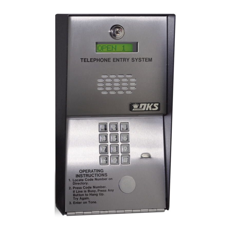
Installation/Owner's Manual
Use this manual for circuit board 1862-010 Revision O or higher.
1803
1803
1803
1808
1808
1808
1810
1810
1810
Date Installed:
Installer/Company Name:
Phone Number:
Leave Manual with Owner
UL Listed
Control a main entry point plus an additional entry point.
F l u
s h
M o
u n
t
T E
L E
P H
O N
E E
N T
R Y
S Y
S T
E M
1 1
2 2
4 4
3 3
5 5
7 7
6 6
8 8
9 9
0 0
O P
1 .
L o
E R
2 .
c a
A T
P re
te
C o
I N
s s
P re
d e
G
C o
I N
3 .
s s
d e
N u
E n
m
S T
" #
N u
b e
te
"
m
r o
R U
r o
to
n
b e
n
C T
T o
H a
r.
D ir
n g
If
I O
n e
L in
e c
.
U P
to
N S
. T
e
r y
is
.
ry
A g
B u
s y
a in
,
.
1 8
0 3
- 0 8
4
S u
r f a
w i t
c e
h D
M o
i r e
u n
c t o
r y
1 1
2 2
4 4
3 3
5 5
6 6
7 7
N A
N A
8 8
M E
M E
A d
A d
am
am
9 9
B er
B er
s J
s J
C O
C O
D E
D E
n ar
n ar
B ro
B ro
d E
d E
0 0
w n
w n
D av
D av
1
1
L
L
is T
is T
9
9
H o
H o
d g es
d g es
5
5
M ill
M ill
er
er
S
S
2
2
S m
S m
J
J
it h
it h
4
4
T h o
T h o
K
K
m as
m as
6
6
Z im
Z im
m er
m er
W
W
8
8
R
R
3
3
7
7
1 8
0 8
- 0 8
2
F l u
s h
M o
u n
t
1 1
2 2
4 4
3 3
5 5
7 7
6 6
8 8
9 9
0 0
1 8
1 0
- 0 8
4
Circuit Board
Serial Number
and Revision Letter:
Copyright 2016 DoorKing, Inc. All rights reserved.
1803 / 1808 / 1810
1803 / 1808 / 1810
1803 / 1808 / 1810
Telephone Entry System
S u
1 8
0 3
t
1 8
0 8
S u
1 8
1 0
Model Number
Copyright 2009 DoorKing, Inc. All rights reserved.
1800-060-D-10-16
r f a
c e
M o
u n
t
T E
L E
P H
O N
E E
N T
R Y
S Y
S T
E M
1 1
2 2
4 4
3 3
5 5
7 7
6 6
8 8
9 9
0 0
O P
1 .
L o
E R
c a
2 .
A T
P re
te
C o
I N
s s
d e
G
P re
C o
N u
I N
3 .
s s
d e
E n
" #
m
S T
te
N u
b e
r o
"
m
r o
R U
to
b e
n
H a
r.
n
C T
T o
D ir
n e
n g
If
e c
I O
L in
N S
.
U P
to
. T
e
r y
ry
is
.
B u
A g
a in
s y
,
.
M O
D E
L 1
8 0
3
- 0 8
0
S u
r f a
c e
M o
u n
t
1 1
2 2
4 4
3 3
5 5
6 6
7 7
P u
P u
8 8
s h
s h
9 9
B u
B u
T o
T o
t t o
t t o
0 0
C a
C a
n
n
ll
ll
- 0 8
4
r f a
c e
M o
u n
t
1 1
2 2
4 4
3 3
5 5
7 7
6 6
8 8
9 9
0 0
- 0 8
0
Advertisement
Table of Contents

Related Manuals for DKS 1803


Summary of Contents for DKS 1803
- Page 1 Installation/Owner’s Manual 1803 / 1808 / 1810 1803 / 1808 / 1810 1803 / 1808 / 1810 Telephone Entry System Use this manual for circuit board 1862-010 Revision O or higher. 1800-060-D-10-16 Control a main entry point plus an additional entry point.
- Page 2 QUICK GUIDE: Terminal Descriptions CLCK SENSE KEYPAD Located in the upper left corner of circuit board. Switch Input 2 3 2 1 Terminal MIC VOL Non-Removable FEEDBACK A closure between these terminals will cause Relay 2 3 2 1 to activate for the programmed strike time or 3 2 1 dial a preprogrammed...
- Page 3 Overview for System Programming Page # Section Command Factory Setting Section 3.1 General Programming Master Master Code 3.1.1 Switch ON 9 9 9 9 Single or Multiple Systems 3.1.2 * 04 0 (single) Relay Strike Time 3.1.3 * 03 Relay 1= 01 (1 sec) Relay 2= 01 (1 sec) “Tone Open”...
- Page 4 SPECIFICATIONS 1803 / 1808 / 1810 Telephone Entry Systems, Circuit Board 1862-010 REV O or Higher. t t o t t o “ # ” 1 8 0 r f a 1 8 0 F l u 1 8 1...
-
Page 5: Table Of Contents
Flush Mount Kit Installation for 1803 & 1810 1.3.2 Self-Standing Lighted Kiosk for 1803 & 1810 1.3.3 Flush Mount Surface Mounting Kit Installation for 1803 & 1810 1.4 1808 Dimensions and Installation 1.4 Memory Chip Replacement 1.5 Postal Lock Installation SECTION 2 - WIRING 2.1 Wiring Guidelines... - Page 6 TABLE OF CONTENTS SECTION 3 - PROGRAMMING Continued 3.2 Phone Number Programming 3.2.1 Programming the Directory Code Length 3.2.2 # Key - Insert an Amount of “Pause Time” Between Phone Number Digits 3.2.3 Programming Phone Numbers - Up to 16-Digits 3.2.4 Deleting Individual Phone Number 3.2.5...
- Page 7 FCC – United States This equipment has been tested and found to comply with the limits for a class A digital device, pursuant to Part 15 of the FCC Rules and Regulations. These limits are designed to provide reasonable protection against harmful interference when the equipment is operated in a commercial environment.
- Page 8 General Information • Prior to beginning the installation of the telephone entry system, we suggest that you become familiar with the instructions, illustrations, and wiring guidelines in this manual. This will help insure that you installation is performed in an efficient and professional manner. •...
-
Page 9: Section 1 - Installation
1.1 General Installation There are 2 different styles of the telephone entry systems (Surface mounts and Flush mounts-1803/1810 only), and different ways to mount them (On a wall, in a wall, attached to a architectural style post, kiosk, etc). Models will ALL need a telephone line, power and communication wires run to them in conduit or inside a architectural style post. - Page 10 6. Remove the faceplate, main terminal (still wired), store them in a Safe Place until they need to be re-installed. 7. Proceed to section 1.2.1 for 1803 & 1810 models. Go to section 1.4 for 1808 model. R I N...
- Page 11 1.1.2 Install Enclosure for 1803 & 1810 There are 2 different styles for the 1803 & 1810 - surface and flush mount. The illustrations below show typical installations Mount a Surface but specific installations can vary from this. (See sections 1.2).
-
Page 12: 1803 & 1810 Surface Mount Dimensions
Surface mount units can be mounted directly to a wall, pilaster, post mounted using a DoorKing architectural style mounting post (P/N 1200-037 and 1200-038) or recessed in a wall (see next page) with the surface mount recess kit (P/N 1803-150). Be sure the unit is mounted securely and is not subject to vibration from closing doors or gates. - Page 13 1.2.1 Surface Mount Recess Kit Installation for 1803 & 1810 1803 & 1810 surface mount units can be Mount In a Surface c k n recessed into a wall or pilaster by using the optional surface mount recess kit if desired (P/N 1803-150).
-
Page 14: 1803 & 1810 Flush Mount Dimensions
Flush mount 1803 & 1810 are installed into a wall/kiosk and can be mounted outside, exposed to the weather. It is preferred that they have limited direct exposure to the weather. We suggest that when they are mounted outdoors, it is in a covered protected area. - Page 15 1.3.1 Flush Mount Kit Installation for 1803 & 1810 The flush mount kit has two c k n parts; the rough-in box and the P l a s t i c trim ring. The rough-in box is a c e Mount In a Surface installed in the wall first.
- Page 16 The flush mount kit (Sold separately) is installed into the self-standing c k n s t i c kiosk (P/N 1200-170) to secure the flush mount 1803 or 1810 in place. a c e Secure the rough-in box in the kiosk. Run all necessary wires to rough-in box.
- Page 17 1.3.3 Flush Mount Surface Mounting Kit Installation for 1803 & 1810 Flush mount unit (See page 10 for flush mount enclosure dimensions) can be t i n ( N o t s u mounted ON a wall or pilaster and NOT IN...
-
Page 18: 1808 Dimensions And Installation
1.4 1808 Dimensions and Installation 1808 units can be mounted directly to a wall, pilaster, post mounted using a DoorKing mounting post (P/N 1200-045 or 1200-046). Be sure the unit is mounted securely and is not subject to vibration from closing doors or gates. WARNING! If this entry system is used to control a... -
Page 19: Memory Chip Replacement
Discharge any static electricity from your hands by touching a proper ground device before installing chip! 1862-010 Circuit Board Memory Chip Location CONTRAST DOORKING 1862-010 Dimple MUST be at the top of the chip! LCD Display (Models 1803 and 1810 only) MASTER CODE l e a CLCK... -
Page 20: Postal Lock Installation
Post Office uses for gang mailboxes. These locks are not available to the public. The installer or the building owner/manager will have to call the Post Office and arrange for the installation of this lock into the telephone entry system. DoorKing 1803 &... -
Page 21: Section 2 - Wiring
SECTION 2 - WIRING Prior to installing wiring to the telephone entry system, we suggest that you become familiar with the instructions, illustrations, and wiring guidelines in this manual. This will help insure that you installation is performed in an efficient and professional manner. - Page 22 2.1.3 Grounding Proper grounding of this system is a requirement. To be effective, ground connections should be made with a minimum 12 AWG, 600 volt insulated wire to a ground point within 10 feet of the telephone entry system. The ground point must be at an electrical panel, a metallic cold water pipe that runs in the earth, or a stainless steel grounding rod driven at least ten (10) feet into the soil.
-
Page 23: Terminal Descriptions
2.2 Terminal Descriptions CLCK SENSE KEYPAD Located in the upper left corner of circuit board. Switch Input 2 3 2 1 Terminal MIC VOL Non-Removable FEEDBACK A closure between these terminals will cause Relay 2 3 2 1 to activate for the programmed strike time or 3 2 1 dial a preprogrammed... -
Page 24: Telephone Entry System Wiring And Adjustments
LCD Display Switch Input 2 - WLAN information. A switch closure across these terminals (1803 & 1810 only) activates Relay 2 for its programmed strike time or dials a preprogrammed phone number. See section 3.1.7 Switch Input Feature. REMOTE... - Page 25 1/8 turn and re-test the system. You may have to perform this step several times to find the correct adjustment. 2.3.3 LCD Display Contrast for 1803 & 1810 LCD display is adjusted at the factory and should NOT need to be re-adjusted. If it does, Let the system run for at least 10-minutes before making any display contrast adjustments.
- Page 26 30 seconds. This tone will continue every 30 seconds until a new master code is entered, or until the switch is turned off. After the switch is turned off, the LCD display on 1803 &...
-
Page 27: Section 3 - Programming
SPKR 16AC 16AC step is ended. The LCD display on 1803 & 1810 models will prompt you for information that you will need to enter. Programming from an Offsite Location Follow these steps when programming the system from an offsite location (remote). You MUST use a touch-tone telephone and the RING jumper (section 2.3.5) MUST be installed to perform off site (remote) programming. - Page 28 Overview for System Programming Page # Section Command Factory Setting Section 3.1 General Programming Master Master Code 3.1.1 Switch ON 9 9 9 9 Single or Multiple Systems 3.1.2 * 04 0 (single) Relay Strike Time 3.1.3 * 03 Relay 1= 01 (1 sec) Relay 2= 01 (1 sec) “Tone Open”...
- Page 29 PQRS PQRS 1. Press and enter your four-digit MASTER CODE (beep). The 1803 & 1810 LCD display will read: 1=Y 0=N OPER OPER 2. Enter for YES - tone will sound or for NO - tone will not sound, then press (beep).
- Page 30 3.1.6 Tone Open Numbers These steps will program the tone open numbers for Relays 1 and 2. You will need to enter a four-digit number (see chart below) to set the relay functions. If a function is not desired, enter # in place of a number. Fill out log table in back of this manual for desired tone open numbers.
- Page 31 3.1.9 PBX Line Access Code Programming If the telephone entry system is connected to a PBX telephone system rather than a dedicated C.O. line, you may need to set the unit to dial a line access code prior to dialing the resident phone number. Typically, the line access code is “9”, but check with the PBX system administrator to be sure.
- Page 32 3.1.13 Automatic Hang-up Function This programming sequence determines when the phone system will automatically hang itself up after a predetermined time of inactivity. You can program the system to not hang-up (0), to hang-up after 5 sec of dial-tone (1), to hang-up after 15 sec of silence (2) or to hang-up after either 5 sec of dial-tone or 15 sec of silence (3).
- Page 33 3.2 Directory Code and Phone Number Programming Up to 16-Digit Phone Numbers can be programmed into the phone system when using the factory default settings (sections 3.2.1 - 3.2.7). The phone system can store up to 600 Phone Numbers. It has the capability of storing up to 1000 phone numbers.
- Page 34 3.2.3 Programming Phone Numbers - Up to 16-Digits In this programming sequence, the directory codes and phone numbers (up to 16 digits) will be programmed into the system. Be sure you have programmed the directory code length that you desire as described in section 3.2.1. Changing the directory code length (Section 3.2.1) AFTER programming the telephone numbers will ERASE ALL the phone numbers and directory codes that have been previously programmed in.
- Page 35 3.2.6 Display / DELETE Phone Numbers with UNKNOWN Directory Codes For 1803 & 1810 models ONLY. This program sequence is useful to display phone numbers when you DO NOT KNOW what directory code they have been programmed under. This sequence also gives you the option to delete the phone number after it is displayed.
- Page 36 ERASED. 1. Press and enter your four-digit MASTER CODE (beep). 2 sec. LCD display on 1803 & 1810 models will read: 7 DIG?..then the LCD display will read: 1=Y 0=N. OPER OPER 2.
- Page 37 3.2.10 Programming 7-Digit Phone Numbers In this programming sequence, the directory codes and 7-digit phone numbers will be programmed into the system. Be sure you have programmed section 3.2.8 to YES (7-digit capability) and the directory code length that you desire in section 3.2.1. Changing the directory code length AFTER programming the telephone numbers will ERASE ALL the phone numbers and directory codes that have been previously programmed in.
- Page 38 3.2.12 Programming Phone Numbers WITH Area Code Reference Numbers Program phone numbers that are referenced to an area code (long distance and 10-digit dialing calls). Make sure that the area code(s) have already been programmed with area code reference numbers in previous section 3.2.11. Be sure you have programmed section 3.2.8 to YES (7-digit capability) and the directory code length that you desire in section 3.2.1.
-
Page 39: Entry Code Programming
3.3 Entry Code Programming 3.3.1 Programming Four-Digit Entry Code This programming sequence programs four-digit entry codes into the system memory. The number of four-digit entry codes that can be programmed is the same as the telephone number memory capacity, plus 12. We suggest that all entry codes that are programmed into the system be listed with the names of residents that they have been assigned to (see log tables in back of this manual). - Page 40 3.3.5 "Hold Four-Digit Entry Codes" - Reverse Relay Activation ONLY A four-digit entry code can be programmed to reverse the condition of relay 1 or relay 2 ONLY. If a relay is NOT activated, entering one of these entry codes will activate it and keep it activated (Hold). If a relay is activated, entering one of these entry codes will release it. (4) entry codes can be assigned to each relay using specific Hold Code numbers.
-
Page 41: Time Functions Programming
3.4 Time Functions Programming 3.4.1 Programming Time Clock This programming sequence programs the calendar chip in the telephone entry system for the current time and date. The calendar chip MUST be programmed if you are going to use any of the time functions available with the entry system. 1. - Page 42 3.4.3 Four-Digit Entry Codes Time Zone This programming sequence sets up ONE time zone for the FOUR-digit entry codes to activate the system relays. This time zone uses a range of four-digit entry codes (Boundary numbers) and can be programmed for certain days of the week. This time zone can be turned ON and turned OFF after it is programmed (see operating instructions 4.2.4 to turn ON or OFF the programmed entry code time zone).
- Page 43 3.4.4 Five-Digit Entry Codes Time Zone This programming sequence sets up ONE time zone for the FIVE-digit entry codes to activate the system relays. This time zone uses a range of five-digit entry codes (Boundary numbers) and can be programmed for certain days of the week. This time zone can be turned ON and turned OFF after it is programmed (see operating instructions 4.2.4 to turn ON or OFF the programmed entry code time zone).
-
Page 44: Section 4 - System Operating Instructions
SECTION 4 - SYSTEM OPERATING INSTRUCTIONS 1 8 0 4.1 General Instructions P re P re “ # ” D ir L in 4.1.1 Guest Instructions a in Instructions on the faceplate of the unit will instruct guest on the operation of the telephone e r a entry system. -
Page 45: System Administrator
4.2 System Administrator The administrator can perform the following operations from a remote location (off-site) using a touch-tone telephone. You must know the phone number of the system and the system’s four-digit MASTER CODE. 4.2.1 Remote Programming (Touch-Tone Phone) 1. Call the telephone number that the entry system is installed on. The system will answer with a short tone (beep heard). Note: the number of rings before the system answers is dependent on the programming in 3.1.8. - Page 46 4.2 System Administrator Continued 4.2.4 Remote Entry Code Time Zone Enable / Disable The entry code time zones can be turned OFF (disable) or ON (enable) remotely from a touch-tone telephone at any time without changing the time zone boundaries. To program the time zone boundaries, see sections 3.4.3 and 3.4.4. Entry code time zones can also be turned off or on at the system keypad by skipping step 1 and proceeding directly to step 2 in the sequence below.
-
Page 47: Miscellaneous Operating Instructions
4.3 Miscellaneous Operating Instructions 4.3.1 Switch Input 1 & 2 Operation The two switch inputs can be programmed to either activate their respective relay (switch input 1 activates relay 1; switch input 2 activates relay 2) or they can be programmed to call the phone number programmed under the first two directory codes (switch input 1 calls the phone number programmed under directory code 0, 00, 000 or 0000) (switch input 2 calls the phone number programmed under directory code 1, 01, 001 or 0001). -
Page 48: Section 5 - Maintenance
SECTION 5 - MAINTENANCE The DoorKing telephone entry system is essentially a maintenance free device. When the unit is properly installed, it should provide years of trouble free service. Maintenance is limited to updating the directory and phone number and/or entry codes when residents move in or out. - Page 49 Symptom Possible Solution(s) • Disconnect the phone line from the system and check it with a handset. If line is noisy, problem is with the phone line and not the entry system. • Check for any shorts to ground behind the circuit board. •...
-
Page 50: Accessories
Use to surface mount a flush style unit. P/N 1814-152. Stainless Steel Case Surge Suppressors Replaces the black steel surface mount case on the 1803 and Phone line suppressor. P/N 1877-010. 1810 units with a stainless steel case. P/N 1810-102. - Page 51 6.1 Log Tables Complete the information in the tables on the following pages to maintain a record of the information that has been programmed into the telephone entry system. Factory - 9999 Master Code (section 3.1.1) Relay Strike Time (section 3.1.3) 1st Digit 2nd Digit 3rd Digit...
- Page 52 Residents Information Make additional copies of this table as needed. Alternate Area Code may be needed when using 7-Digit Phone Numbers Programming ONLY, see sections 4.3.4 and 4.3.5 for more info. NAME AREA CODE PHONE NUMBER DIRECTORY CODE ENTRY CODE ALT.
- Page 53 RESIDENT INSTRUCTIONS Your building / community has been equipped with a DoorKing Telephone Entry System that will provide communication for your guest from the lobby door / gated entrance to your home by use of the local telephone network. If you have any questions regarding the use or operation of this system, please see your System Administrator (building manager / HOA representative) or Call: Phone #...
- Page 54 Installation/Owner’s Manual 1803 / 1808 / 1810 1803 / 1808 / 1810 1803 / 1808 / 1810 Telephone Entry System Use this manual for circuit board 1862-010 Revision O or higher. 1800-060-D-10-16 Control a main entry point plus an additional entry point.
Need help?
Do you have a question about the 1803 and is the answer not in the manual?
Questions and answers