
Related Manuals for SunStar SPS/E-BS1201 Series


Summary of Contents for SunStar SPS/E-BS1201 Series
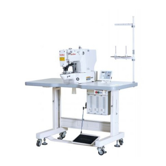
- Page 1 User’s Manual SPS/E-BS1201 Series SPS/E-BR1201 Series Electronically Controlled Bartack Sewing Machine (Machine Structure Part)
- Page 2 1. Thank you for purchasing our product. Based on the rich expertise and experience accumulated in industrial sewing machine production, SUNSTAR will manufacture industrial sewing machines, which deliver more diverse functions, high performance, powerful operation, enhanced durability, and more sophisticated design to meet a number of user’s needs.
-
Page 3: Table Of Contents
Contents ................6 1) Machine Type and Specifications 2) Safety Rules ......................... 7 2.1) Safety Stickers ........................7 2.2) Machine Delivery ......................8 2.3) Machine Installation ......................9 2.4) Machine Operation ......................9 2.5) Repair and Maintenance ....................10 2.6) Type of Safety Labels ...................... 10 2.7) Location of Safety Labels .................... - Page 4 6) Maintenance ........................24 6.1) Adjustment of Needle Bar Height .................. 24 6.2) Adjustment of Needle and Hook ..................24 6.3) Adjustment of Lower Shaft Gear and Oscillating Shaft (BS-Semi-rotary) ....25 6.4) Adjustment of Shuttle Upside Spring Position (BS-Semi-rotary) ......... 25 6.5) Adjustment of Presser Foot Height .................
-
Page 5: Machine Type And Specifications
Machine Type and Specifications Bartack Sewing Machine Model SunStar Pattern Belt Loop System (For Belt Loop Attachment) Series Type E-Series Bartack Sewing H : Heavy materials Machine Name M : General materials S : Shuttle Hook L : Light materials... -
Page 6: Safety Rules
Safety Rules 2.1) Safety Stickers The safety stickers in this user’s manual are divided into Caution Danger , and Warning . They indicate that if the safety rules are not kept, injury or damage to machine might occur as a result. Name Description If the machine is not properly handled, it may cause injury to... -
Page 7: Machine Delivery
2.2) Machine Delivery Mark Description The machine delivery shall be conducted by the persons who are knowledgeable about the safety instructions and rules. The following safety rules must be observed: 2.2.1) Manual delivery When the machine is delivered by persons, they shall wear special shoes and tightly hold the machine on the left and right sides. -
Page 8: Machine Installation
2.3) Machine Installation Depending on the installation environment, function errors, breakdown, or other physical damage might result. Make sure to meet the following conditions for machine installation: 1) The workbench or table where the machine is installed should be durable enough to endure the weight of the machine (see the name plate). -
Page 9: Repair And Maintenance
2) Do not modify the machine specifications or parts without substantial consultations with SunStar. Otherwise, it may threaten safety during machine operation. 3) Use the parts manufactured by SunStar to repair or replace the machine parts during A/S service. 4) When repairing is completed, re-install all the removed safety covers. -
Page 10: Location Of Safety Labels
2.7) Location of Safety Labels... -
Page 11: Assembly
Assembly 3.1) Name of Machine Parts 3.1.1) Name of Machine Parts Motor Cover Thread Stand Safety Plate OP Box Power Switch Control Box Pedal... -
Page 12: Machine Installation
Machine Installation 4.1) Installation Environment 1) To prevent accidents stemming from mal-operation, do not use the machine if the voltage is 10% above the rated voltage. 2) To prevent accidents stemming from mal-operation, make sure to check if the air pressure is proper before using any air pressure devices such as air cylinder. -
Page 13: Machine Installation
To prevent safety accidents, at least two persons shall be assigned to machine installation or machine delivery. Caution 4.4) Machine Installation 1) Install the waste oil can support, the oil dish, the control Oil Dish box, and the power switch on the table. Waste Oil Can Support Power Switch... - Page 14 4) Since the machine has not been fully assembled, take caution to lean the assembled machine on the floor, Fixing Bolt and insert and fasten the bolt into the hinge to completely fix the machine to the table. To prevent safety accidents, at least two persons shall be assigned to machine installation or machine delivery.
-
Page 15: How To Install The Table (Ba Type)
4.5) How to install the table (BA type) 1) Fix the oil container support , the oil dish , and the control box on the table (below). 2) Fix the power switch on the table (above). 3) Assemble the bed cushion rubber on the table (below). - Page 16 To prevent safety accident, the machine should be carried by at least two people. Danger 7) Open the hinge area on the table (above) and erect the sewing machine. Insert the fixing bolt into the hinge hole and fix it on the table. Fixing bolt The machine has not been completely assembled.
-
Page 17: Accessory Installation
4.6) Accessory Installation Fixing Screw 4.6.1) Installation of Motor Cover Motor Cover Attach the motor cover to the rear side of the machine by using four fixing screws (4EA, small size). 4.6.2) Installation of Safety Plate Face Plate Attach the safety plate to the head. Safety Plate To guarantee safety, make sure to install the safety plate before using the machine. -
Page 18: Machine Operation
5.1.1) Supplying Location In the first operation of the sewing machine, check the remaining volume of oil through the oil window and supply oil if it is found insufficient. 5.1.2) Grease Supply Administer the original SunStar grease product to the necessary parts. -
Page 19: Needle
5.2) Needle 5.2.1) Needle Installation Loosen the needle fixing screw. With the long groove of the needle headed forward, insert the needle until the Needle Fixing Screw upper end of the needle touches the end of the hole, and fix the needle by using the needle fixing screw. Needle 5.3) Thread 5.3.1) Upper and Lower Thread Placement... -
Page 20: 2) Bobbin Case Insertion/Removal
5.3.2) Bobbin Case Insertion/Removal Open the hook cover and push the bobbin into the hook by holding the bobbin case handle until you hear some sound. If the bobbin case and the hook are not accurately assembled, thread might be entangled or the bobbin case might be ejected during machine operation. -
Page 21: 4) Lower Thread Winding
5.3.4) Lower Thread Winding 1) Press “Select” on OP Box and select the bobbin winder. 2) Insert the bobbin into the thread winding shaft on the thread winding base, which is attached to the top cover. 3) Attach the thread winding lever to the bobbin, and press the pedal to operate the machine. -
Page 22: Pressured Air Infusion And Adjustment Of Air Pressure (Ha Type)
5.5) Pressured Air Infusion and Adjustment of Air Pressure (HA type) To prevent safety accidents from occurring, make sure that the power is off during this adjustment. Caution 5.5.1) Pipe Connection for Pressured Air Connect the quick joint plug which is attached to the Finger Valve table to the quick joint socket where pressured air flows in. -
Page 23: Maintenance
Maintenance 6.1) Adjustment of Needle Bar Height Tightening DP 15 Place the needle bar at the lowest position, and loosen the Screw needle bar holder screws. Find an upper punched mark in line with the specification of the needle to be applied and make it touch the bottom of the needle bar bushing. -
Page 24: Adjustment Of Lower Shaft Gear And Oscillating Shaft (Bs-Semi-Rotary)
6.3) Adjustment of Lower Shaft Gear and Oscillating Shaft (BS : Semi-rotary) Loosen tightening screws , and Rotate the upper shaft and move the oscillating gear in the arrow direction to find the position where the gear can smoothly operate without any load. Attach the oscillating shaft collar (right) to the bed face and fasten the collar screw . -
Page 25: Adjustment Of Presser Foot Height
6.5) Adjustment of Presser Foot Height After the presser foot height adjustment is completed, tightly fasten each tightening screw. During machine operation, if the presser foot might be loosened, and it may cause damage. Caution 6.5.1) For General, Heavy, Light Materials and Knit Loosen the screws for the lift lever adjusting plate on the left and right sides of the feed bracket , and lift the adjustment plate... -
Page 26: 3) Adjustment Of Thread Guide Disk Opening
Trimmer Drive Link Thread Release Lever Pin Thread Release Return Spring 0.3mm Thread Release Stopper Tightening Screw Wider Narrower 6.6.3) Adjustment of Thread Guide Disk Opening Loosen the tightening screw for the thread release adjustment plate. Conduct thread trimming to make the thread guide disk open. Adjust the guide disk to be open 0.6~0.8mm for general materials and 0.8~1mm for heavy materials respectively. -
Page 27: Adjustment Of Wiper-Related Parts
6.7) Adjustment of Wiper-related Parts Loosen the tightening screw for the wiper base plate. Make the needle vertically aligned with the wiper at the center. Adjust the wiper base plate up or down to set the distance between the needle plate and the wiper to Needle be 14~15mm. -
Page 28: 2) Adjustment Of Link Stopper Screw
6.8.2) Adjustment of Link Stopper Screw With the needle bar at the lowest position, push the trimmer driving link in the direction of the trimmer cam within the trimmer cam operation zone. And check whether there is space between the trimmer cam roller and the both ends of the trimmer cam. -
Page 29: 5) Trimmer Solenoid Position Setting
6.8.5) Trimmer Solenoid Position Setting Loosen the tightening screw for the trimmer solenoid bracket and set the distance between the trimmer shaft and the trimmer solenoid rotary link to be 0.5mm. When the setting is completed, fasten the tightening screw. Loosen the tightening screw for the solenoid rotary link and manually move the rotary link of the trimmer solenoid toward the trimmer shaft collar by 6.8mm in the arrow direction. -
Page 30: Adjustment Of Thread Volume On Bobbin
6.9) Adjustment of Thread Volume on Bobbin Bobbin To adjust the thread volume wound on the bobbin, use the initial position of the thread winder adjusting plate. If lots of thread is wound, loosen the tightening screw on the thread winder adjusting plate and turn it to the A direction. -
Page 31: Assembly And Adjustment Of Direct Drive Motor
6.11) Assembly and Adjustment of Direct Drive Motor No. 1 Tightening Screw Servo Motor 6.11.1) Assembly of coupling O-Ring Assembly of Servo Motor Coupling Upper Shaft When installing the coupling on the servo motor, accurately locate the tightening screws for the coupling on the connection parts, adjust the distance Connection Part between the coupling and the servo motor to be... -
Page 32: 2) Y Origin Setting
Abnormal operation due to dust or foreign materials gathered at the moving parts 1) If machine damage or mal-operation occurs due to the failure to clean and lubricate the machine through regular checking, SunStar will not be held liable. 2) Adjust the cleaning cycle depending on the use conditions and environment. -
Page 33: 2) Oil Supply
6.13.2) Oil Supply 1) Type of Lubricant Type of Lubricant Parts Applied S/M oil Arm, Bed, Hook Silicon oil Silicon oil supply tank Grease Presser Plate 6.13.3) Oil Supply Method 1) Arm Check the remaining oil volume at the oil tank installed at the arm before supplying oil. -
Page 34: 4) Grease Lubrication
4) Silicon Oil Tank Supply silicon oil to the silicon oil tank installed on the right side of the arm. 6.13.4) Grease Lubrication 1) Turn off the machine power. 2) Loosen the screws. 3) Lubricate grease on the parts marked with arrows. 4) Assemble the screw. -
Page 35: Cleaning
6.14) Cleaning 6.14.1) Cleaning Cycle and Method 1) Make sure to turn “off” the machine power before conducting cleaning. 2) Assemble the parts which are disassembled for cleaning. Caution Cleaning Area Cleaning Frequency Around hook Everyday Thread take-up lever / Thread tension adjusting device Once a week Around the moving and fixed blades. -
Page 36: Troubleshooting
Troubleshooting 7.1) Machine Part Trouble Cause Corrective Action Excessive relaxation of the belt tension or Adjust the belt tension and replace the belt the damage to the belt Power cutoff or the cut of the circuit fuse Check whether the main shaft motor drive Faulty machine fuse is cut and replace it if so. - Page 37 Trouble Cause Corrective Action Weak upper thread tension Adjust the upper thread tension Bad thread tightening Weak lower thread tension Adjust the lower thread tension condition Improper needle and shuttle timing Adjust the needle and shuttle timing Loose crossing tension between moving and Adjust the tension of the fixed blade fixed blades Missing thread...
Need help?
Do you have a question about the SPS/E-BS1201 Series and is the answer not in the manual?
Questions and answers