Table of Contents
Advertisement
S S U U N N S S T T A A R R M M A A C C H H I I N N E E R R Y Y C C O O . . , , L L T T D D . .
R
User's
Manual
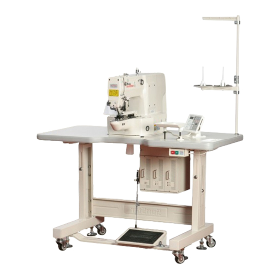
SPS/E-BS1202 Series
SPS/E-BR1202 Series
Electronically Controlled
Button Sewing Machine
(Mechanical Part)
1) FOR AT MOST USE WITH EASINESS,
PLEASE CERTAINLY READ THIS MANUAL
BEFORE STARTING USE.
2) KEEP THIS MANUAL IN SAFE PLACE
FOR REFERENCE WHEN THE MACHINE
BREAKS DOWN.
M M M M E E - - 0 0 6 6 0 0 7 7 1 1 3 3
Advertisement
Table of Contents

Related Manuals for SunStar SPS/E-BS1202 Series


Summary of Contents for SunStar SPS/E-BS1202 Series
-
Page 1: Mechanical Part
User’s Manual SPS/E-BS1202 Series SPS/E-BR1202 Series Electronically Controlled Button Sewing Machine (Mechanical Part) 1) FOR AT MOST USE WITH EASINESS, PLEASE CERTAINLY READ THIS MANUAL BEFORE STARTING USE. 2) KEEP THIS MANUAL IN SAFE PLACE FOR REFERENCE WHEN THE MACHINE BREAKS DOWN. - Page 2 1. Thank you for purchasing our product. Based on the rich expertise and experience accumulated in industrial sewing machine production, SUNSTAR will manufacture industrial sewing machines, which deliver more diverse functions, high performance, powerful operation, enhanced durability, and more sophisticated design to meet a number of user’s needs.
-
Page 3: Table Of Contents
Contents ................6 1. Machine Type and Specifications 2. Safety Rules ......................... 7 2.1) Safety Stickers ........................7 2.2) Machine Delivery ......................8 2.3) Machine Installation ......................9 2.4) Machine Operation ......................9 2.5) Repair and Maintenance ....................10 2.6) Devices for safety ......................10 2.7) Location of Safety Labels .................... - Page 4 6.11) Adjustment of Hand Pulley Device ................29 6.12) Assembly and Adjustment of Direct Drive Motor ............29 6.13) Setting up the X-Y Origin ..................... 29 6.14) How to adjust the feeding plate ................... 30 6.15) Checking the setting position of button clamp ............. 30 6.16) How to set up the button clamp adjusting plate ............
-
Page 5: Machine Type And Specifications
Machine Type and Specifications Bartack Sewing Machine Model SPS / E- B 1202 ① SunStar Pattern ⑤ Button Type System 01 : Small-Size Button (Mechanical Type Wiper) 02: Large-Size Button (Mechanical Type Wiper) ② Series Type 03 : Small & Large Size Button E:Motor direct drive-type... -
Page 6: Safety Rules
Safety Rules 2.1) Safety Stickers Caution Danger Warning The safety stickers in this user’s manual are divided into , and . They indicate that if the safety rules are not kept, injury or damage to machine might occur as a result. Name Description If the machine is not properly handled, it may cause injury to... -
Page 7: Machine Delivery
2.2) Machine Delivery Mark Description The machine delivery shall be conducted by the persons who are knowledgeable about the safety instructions and rules. The following safety rules must be observed: 2.2.1) Manual delivery When the machine is delivered by persons, they shall wear special shoes and tightly hold Danger the machine on the left and right sides. -
Page 8: Machine Installation
2.3) Machine Installation Depending on the installation environment, function errors, breakdown, or other physical damage might result. Make sure to meet the following conditions for machine installation: 1) The workbench or table where the machine is installed should be durable enough to endure the weight of the machine (see the name plate). -
Page 9: Repair And Maintenance
2) Do not modify the machine specifications or parts without substantial consultations with SunStar. Otherwise, it may threaten safety during machine operation. 3) Use the parts manufactured by SunStar to repair or replace the machine parts during A/S service. 4) When repairing is completed, re-install all the removed safety covers. -
Page 10: Location Of Safety Labels
2.7) Location of Safety Labels CAUTION 경 고 Do not operate without finger guard and safety devices. Before threading, changing bobbin and needle, cleaning etc. switch off main switch. 손가락 보호대와 안전장치 없이 작동하지 마십시오. 실, 보빈, 바늘교환시나 청소전에는 반드시 주전원의... -
Page 11: Assembly
Assembly 3.1) Name of Machine Parts 3.1.1) Name of Machine Parts Motor Cover Thread Stand Safety Plate OP Box Power Switch Control Box Pedal... -
Page 12: Machine Installation
Machine Installation 4.1) Installation Environment 1) To prevent accidents stemming from mal-operation, do not use the machine if the voltage is 10% above the rated voltage. 2) To prevent accidents stemming from mal-operation, make sure to check if the air pressure is proper before using any air pressure devices such as air cylinder. -
Page 13: Machine Installation
To prevent safety accidents, at least two persons shall be assigned to machine installation or machine delivery. Caution 4.4) Machine Installation 1) Install the waste oil can support, the oil dish, the Oil Dish control box, and the power switch on the table. Waste Oil Can Support Power... - Page 14 4) Since the machine has not been fully assembled, take caution to lean the assembled machine on the floor, and insert and fasten the bolt into the hinge to completely fix the machine to the table. Fixing Bolt To prevent safety accidents, at least two persons shall be assigned to machine installation or machine delivery.
-
Page 15: Accessory Installation
4.5) Accessory Installation Fixing Screw 4.5.1) Installation of Motor Cover Attach the motor cover to the rear side of the machine by using four fixing screws (4EA, small size). Motor Cover 4.5.2) Installation of Safety Plate Attach the safety plate to the head. Face Plate Safety Plate To guarantee safety, make sure to install the safety plate before using the machine. -
Page 16: Machine Operation
Machine Operation 5.1) How to supply oil 1) Check the remaining oil in the oil tank in the arm and bed, and supply the oil sufficiently on the arrowed parts on the figure with a lubricator. Be sure to supply oil when operating the machine for the first time and when the machine has not been used for a long time. -
Page 17: Needle
5.3) Needle 5.3.1) Needle Installation Needle Fixing Screw Loosen the needle fixing screw. With the long groove of Needle the needle headed forward, insert the needle until the upper end of the needle touches the end of the hole, and fix the needle by using the needle fixing screw. - Page 18 5.4.2) Bobbin Case Insertion/Removal Open the hook cover and push the bobbin into the hook by holding the bobbin case handle until you hear some sound. [ BS Type ] [ BR Type ] Bobbin Case If the bobbin case and the hook are not accurately assembled, thread might be entangled or the bobbin case might be ejected during machine operation.
-
Page 19: Pedal Operation
5.4.4) Lower Thread Winding 1) Press “Select” on OP Box and select the bobbin winder. 2) Insert the bobbin into the thread winding shaft on the thread winding base, which is attached to the top cover. 3) Attach the thread winding lever to the bobbin, and press the pedal to operate the machine. -
Page 20: Maintenance
Maintenance 6.1) Adjustment of Needle Bar Height Tightening Screw DP×15 Place the needle bar at the lowest position, and loosen the needle bar holder screws. Find an upper punched mark in line with the specification of the needle to be applied and make it touch the bottom of the needle bar bushing. -
Page 21: Adjustment Of Lower Shaft Gear And Oscillating Shaft (Bs : Semi-Rotary)
6.2.3) Adjustment of Eccentric Part of Thread Take-up Lever Crank Shaft ③ 1) Disassemble the face plate from the machine, and remove the tightening screw① of the thread take-up lever crank shaft. 2) Loosen the fixing screw② of the thread take-up crank shaft, which is on the left side of the arm. -
Page 22: Adjustment Of Shuttle Upside Spring Position (Bs : Semi-Rotary)
6.4) Adjustment of Shuttle Upside Spring Position (BS : Semi-rotary) - Disassemble the lower feed plate and the needle plate in order to enable the adjustment of the shuttle upside spring. - Loosen the tightening screw which fixes the shuttle upside spring. Place the upper side of the spring in the middle of the back of the needle and the width as in the figure. -
Page 23: How To Adjust The Button Clamp Holder Tension
6.6) How to adjust the button clamp holder tension Adjust it smoothly to the extent that sewing cloth does not move during sewing, and fix it with the tension adjusting nuts - ① and ②. ① ② 6.7) Adjusting the parts of thread release Tightening Screw 1) How to Set the Thread release Notch Notch... -
Page 24: Adjustment Of Wiper-Related Parts
3) How to adjust the opening capacity of the thread guide disk ① Unfasten the thread release adjusting plate screw. ② Open the thread guide disk by operating the trimming devices. ③ Adjust the opening capacity to 0.6~0.8mm for normal material and 0.8~1mm for heavy material. To increase the opening capacity, widen the angle between the thread release plate and narrow the angle to reduce the opening capacity. -
Page 25: Adjustment Of Trimmer-Related Parts
6.9) Adjustment of Trimmer-related Parts 6.9.1) Trimmer Cam Position Setting Set the distance between the upper shaft collar and the trimmer cam to be 1.7mm. Find the location of the trimmer cam where the carved line of the trimmer cam meets with the punched mark of the upper shaft. When the adjustment is completed, fasten the tightening screw①. - Page 26 6.9.3) Trimmer Shaft Position Setting - Loosen the tightening screw for the trimmer driving link and the tightening screw for the trimmer shaft collar. - Make the cross-section of the trimmer shaft touch the A section of the arm. - Fasten the tightening screw. If the position is not properly set, the trimmer operation might be faulty or the parts might be stuck with each other.
-
Page 27: Adjustment Of Thread Volume On Bobbin
6.9.5) Adjustment of Moving and Fixed Blades - When the needle bar stops at the upper stop position, adjust the distance(A) between the thread separation point of the moving blade and the needle plate hole to be the figure described in the table by using the adjusting screw. -... -
Page 28: Adjustment Of Hand Pulley Device
6.11) Adjustment of Hand Pulley Device Hand Pulley Gear Bushing Hand Pulley 1) Make the hand pulley gear touch the end of the hand Shaft Upper pulley shaft, and fasten the tightening screw. Shaft 2) Secure proper clearance between the gear , which is connected to the upper shaft, and the gear , which is connected to the hand pulley shaft, and fasten the tightening screw. -
Page 29: How To Adjust The Feeding Plate
6.13.2) How to set up Y-axis Origin 1) Separate a bed cover (right). 2) Move the center of work clamp foot to be placed on the center of Y-axis. 3) As seen in the figure, unfasten the bolts of Y-sensor plate and let the end of Y-sensor plate locate on the center of sensor, then fasten the bolts with screw-driver. -
Page 30: How To Set Up The Button Clamp Adjusting Plate
- Abnormal operation due to dust or foreign materials gathered at the moving parts 1) If machine damage or mal-operation occurs due to the failure to clean and lubricate the machine through regular checking, SunStar will not be held liable. 2) Adjust the cleaning cycle depending on the use conditions and environment. - Page 31 6.18.2) Oil Supply 1) Type of Lubricant Type of Lubricant Parts Applied S/M oil Arm, Bed, Hook Silicon oil Silicon oil supply tank Grease Presser Plate 6.18.3) Oil Supply Method 1) Arm - Check the remaining oil volume at the oil tank installed at the arm before supplying oil.
- Page 32 4) Silicon Oil Tank - Supply silicon oil to the silicon oil tank installed on the right side of the arm. 6.18.4) Grease Lubrication 1) Turn off the machine power. 2) Loosen the screws. 3) Lubricate grease on the parts marked with arrows. 4) Assemble the screw.
-
Page 33: Cleaning
6.19) Cleaning 6.19.1) Cleaning Cycle and Method 1) Make sure to turn “off” the machine power before conducting cleaning. 2) Assemble the parts which are disassembled for cleaning. Caution Cleaning Area Cleaning Frequency Around hook Everyday Thread take-up lever / Thread tension adjusting device Once a week Around the moving and fixed blades. -
Page 34: Cause Of Breakdown And Troubleshooting
Cause of Breakdown and Troubleshooting Trouble Cause Corrective Action Loosing of belt tension and damage on belt Adjust the belt tension or exchange it Fuse shortage for main power or circuit Check the fuse shortage of main shaft drive Error on operation or motor in a controller box or exchange it drive of machine Deviation from Y and Y limit of feed bracket... - Page 35 Trouble Cause Corrective Action Weak tension of upper thread Readjust the tension of upper thread. Errorin thread Weak tension of lower thread Readjust the tension of lower thread. tightening Improper timing for needle and shuttle Readjust the timing for needle and shuttle Laxity of exchanging tension between Readjust the tension of fixed mes.
-
Page 36: Pattern List
Pattern List Range of Sewing Range of Sewing Pattern No of Pattern No of Pattern Pattern Threads Threads X (mm) Y (mm) X (mm) Y (mm) 10-10 12-12 10-10 12-12 10-10 10-10 10-10 5-5-5 10-10 8-8-8 5-5-5 8-8-8 10-10 ※ The magnifying and reduction range (X and Y) of standard sewing shown above is 100% 66 patterns including 33 patterns can be additionally provided. -
Page 37: Drawing Of Table
Drawing of Table 9.1) SPS/E-BS(R)1202... -
Page 38: Gauge List
1 1 0 0 GAUGE LIST MODEL SPS/E-BS(R)-1202 Button Size Small Button Midium Button Large Button External diameter of Button ф8~ф15 ф10~ф20 ф15~ф32 (mm) 0~3.5 0~4.5 0~6.5 Stitch Size (mm) 0~4.5 0~3.5 0~6.5 Thickness (mm) 1.3 (2.2) 2 (2.7) 2.7 (3.2) Punche Punche Punche...
Need help?
Do you have a question about the SPS/E-BS1202 Series and is the answer not in the manual?
Questions and answers