Table of Contents
Advertisement
S S U U N N S S T T A A R R M M A A C C H H I I N N E E R R Y Y C C O O . . , , L L T T D D . .
R
USER ' ' S
MANUAL
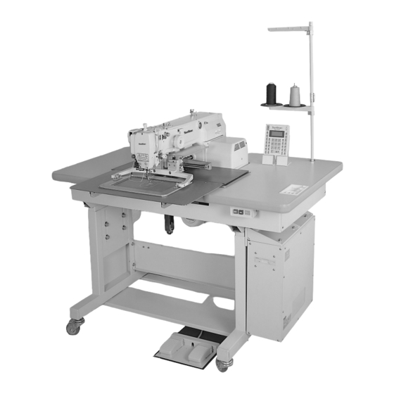
SPS/B-2516 SERIES
SPS/A-2516 SERIES
E E l l e e c c t t r r o o n n i i c c a a l l l l y y C C o o n n t t r r o o l l l l e e d d
P P a a t t t t e e r r n n S S e e w w i i n n g g M M a a c c h h i i n n e e
( ( M M e e c c h h a a n n i i c c a a l l P P a a r r t t ) )
1) FOR AT MOST USE WITH EASINESS,
PLEASE CERTAINLY READ THIS MANUAL
BEFORE STARTING USE.
2) KEEP THIS MANUAL IN SAFE PLACE
FOR REFERENCE WHEN THE MACHINE
BREAKS DOWN.
M M M M E E - - 0 0 4 4 0 0 9 9 2 2 2 2
Advertisement
Table of Contents

Subscribe to Our Youtube Channel
Related Manuals for SunStar SPS/B-2516 Series


Summary of Contents for SunStar SPS/B-2516 Series
- Page 1 USER ’ ’ S MANUAL SPS/B-2516 SERIES SPS/A-2516 SERIES E E l l e e c c t t r r o o n n i i c c a a l l l l y y C C o o n n t t r r o o l l l l e e d d...
- Page 2 1. Thank you for purchasing our product. Based on the rich expertise and experience accumulated in industrial sewing machine production, SUNSTAR will manufacture industrial sewing machines, which deliver more diverse functions, high performance, powerful operation, enhanced durability, and more sophisticated design to meet a number of user’s needs.
- Page 3 Organization of the Pattern Sewing Machine Model SPS / B- 2 5 1 6 - H S - 2 0 Sunstar Feeding frame type Pattern System Series A: Motor belt-type B: Motor direct drive-type Stitch type X : 250mm Sewing area...
-
Page 4: Table Of Contents
CONTENT 1. Machine Safety Regulations 1) Machine Transportation 2) Machine Installation 3) Machine Repair 4) Machine Operation 5) Devices for Safety 6) Caution Mark Position 7) Contents of Marks 2. Specification of machine 3. Structure of the machine 1) Name of each parts of machine 2) Inside structure of control box 4. - Page 5 5) Adjusting the presser foot devices 6) Adjusting the presser foot lifter cylinder 7) Adjusting accessories for thread delay 8) Adjusting accessories for the wiper 9) Adjusting the trimming parts 10) Adjusting the main thread control device 11) Adjusting the upper thread detecting device 12) Adjusting the hand pulley device 13) Adjusting the winding device 14) Adjusting the height of needle plate support cover...
-
Page 6: Machine Safety Regulations
MACHINE SAFETY REGULATIONS Safety instruction on this manual are defined as Danger, Warning and Notice. If you do not keep the instructions, physical injury on the human body and machine damage might be occurred. Danger : This indication should be observed definitely. If not, danger could be happen during the installation, conveyance and maintenance of machines. -
Page 7: Machine Operation
1-4) Machine Operation SPS/B(A)-2516 Series are made for industrial use to perform pattern sewing for fabrics or its similar materials. Please observe the following principles. ⓐ Read the manual to understand on the operation of machine perfectly. ⓑ Wear suitable clothes and cap for safe operation. ⓒ... -
Page 8: Caution Mark Position
1-6) Caution Mark Position Caution mark is attached on the machine for safety. When you operate the machine, observe the directions on the mark. Position of Warning Mark CAUTION 경 고 Do not operate without finger guard and safety devices. Before threading, changing bobbin and needle, cleaning etc. -
Page 9: Specification Of Machine
SPECIFICATIONS OF THE MACHINE Series type SPS/B-2516(Motor direct drive-type) SPS/A-2516(Belt drive-type) Sewing Area X : 250㎜ × Y : 160㎜ Sewing Speed Max. 2,000spm (Stitch Length : 3㎜ or less) Stitch Length 0.1~12.7㎜ Needle DP×17, DP×5 Needle Bar Stroke 41.2㎜ Hook Semi-rotary Large Shuttle Hook Bobbin Case... -
Page 10: Structure Of The Machine
STRUCTURE OF THE MACHINE 1) Names of Each Parts of Machine Emergency Stop Switch Pause Switch Thread Stand Operation Power Switch Control Box Sewing pedal Upper feed plate pedal... -
Page 11: Inside Structure Of Control Box
2) Inside Structure of Control Box Floppy Disk Drive Step Motor Drive Board Main Shaft Power Motor Board Drive Board Transformer IO Board 386 CPU Board... -
Page 12: Installation Of Machine
INSTALLATION OF THE MACHINE 1) Environment for Machine Installation A. Do not use in a place where regularity voltage ± 10% is over for preventing from any accident by wrong operation. B. Check the indicated pressure of the devices that use atmospheric pressure such as the air cylinder to prevent any accidents from occurring. - Page 13 B. Attach the safety plate to the face plate. ⓐ You should attach it for sure to prevent from safe accident. ⓑ Be careful when you start operation. Otherwise, fingers or hand might be hurt at Face Plate the upper feed plate accidentally. Safety Plate [Fig.
- Page 14 E. Table leg holder ▶ Method ⓐ Loosening the nut ① and turn and raise the label adjuster ② until the caster ③ is raced. ⓑ After installation, fasten the nut ① and fix the label adjuster ②. ⓒ With the bolt ④, adjust the height of table by loosening 8 different spots. ④...
-
Page 15: Preparation Before Using The Machine
PREPARATION BEFORE USING THE MACHINE 1) Setting the Voltage A. If a cover of electronically controlled pattern Input Voltage Position of change connector of power voltage sewing machine is taken off, inside contents 95V~105V are as same as [Fig. 7]. B. -
Page 16: How To Supply Oil
2) How to Supply Oil A. Check the amount of oil left in the oil tank which is installed on the arm and supply oil sufficiently. [ Caution ] Be sure to supply oil when operating the machine for the first time or when the machine has not been used for long time. -
Page 17: How To Install The Needle Bar
D. Open the hook cover and supply oil till the shuttle race ring is surrounded by oil. Put the hook cover back on after finishing. [ Caution ] For safety, keep the hook cover covered during operating. Shuttle Race Ring Hook Cover [Fig. -
Page 18: How To Thread The Upper Thread
4) How to Thread the Upper Thread A. Hook the upper as shown in the following picture after setting the thread take-up lever at the highest position. As with the needle bar thread guide, hook the thread as shown in picture ① for heavy materials. -
Page 19: How To Adjust The Tension Of The Upper Thread And The Lower Thread
7) How to Adjust the Tension of the Upper Thread and the Lower Thread A. Adjusting the tension of the upper thread When the tension adjusting nuts ③ and ④, of thread tension adjusting unit ① and sub- tension adjusting unit ②, are turned clockwise the upper thread is tightened. -
Page 20: Adjusting The Height Of The Presser Foot
9) Adjusting the Height of the Presser Foot A. Unfasten presser foot screw ① with the needle bar at the lowest position. B. Adjust the height so that the presser foot bottom comes 0.5mm(the thickness of the thread used)above the sewing material. Then, tighten the screw. -
Page 21: Adjusting The Speed For Ascension And Descent Of Upper Feed Plate
12) Adjusting the Speed for Ascension and Descent of Upper Feed Plate A. Like the fig. ⓐ, if you turn a handle ② on reducing valve ① of solenoid valve attached to the bottom of table clockwise, the ascending speed of upper feed plate and support pressure during ascending will be increased, if you turn it counterclockwise, they are reduced, so that you should adjust it to be proper speed and fix them with fixing nut ③. -
Page 22: How To Attach And Detach V-Belt (A Series)
14) How to attach and detach V-Belt (A Series) A. Loosen a fixing screw of Belt Cover① to disassemble Belt Cover from the sewing machine. B. Loosen a fixing nut② of Motor to rise it up to the arrow. C. When V-Belt tension gets loosened, remove V-Belt. [Fig. -
Page 23: How To Repair The Machine
HOW TO REPAIR THE MACHINE The machine is set to be the best condition at the factory. Do not make any discrete adjustments C C a a u u t t i i o o n n on the machine and replace accessories approved by the company only. 1) Adjusting the height of the needle bar ①... -
Page 24: Adjusting The Lower Shaft Gear And The Rocking Shaft Gear
3) Adjusting the Lower Shaft Gear and the Rocking Shaft Gear A. Unfasten screws ① and ②. B. While having the upper shaft turning, move the rocking shaft gear in the direction of the arrow to the position where it will move easily without load. [ Caution ] The machine may not operate when the rocking shaft gear in not in the right position. -
Page 25: Adjusting The Presser Foot Devices
5) Adjusting the Presser Foot Devices A. Conform the end of presser foot operating cam to the center of punched mark, and conform the cam’ s punched line to the punched mark of upper axis, and then tighten Clamp①. [Cautions] If the presser foot operating cam is improperly positioned, The up-and-down moving of presser foot is in inconformity, therefore the presser foot may collide with the needle bar. - Page 26 F. Check the tightening status of screws, and adjust the presser foot’ s stroke. [Cautions] If there is no interval between Presser Bar Holder and Presser Bushing, the machine may be interfered during its operation. If the handle is completely tightened, the machine may be damaged during its operation.
-
Page 27: Adjusting The Presser Foot Lifter Cylinder
6) Adjusting the Presser Foot Lifter Cylinder A. The distance between the hole center of cylinder knuckle ① and the hole center of presser foot lifter cylinder ② to be 163.2±0.2mm to maximum. B. If you turn a handle ④ of speed controller ③ on presser foot lifter cylinder ② clockwise, the ascending speed of presser foot will be reduced, if you turn it counterclockwise, they are increased, so that you should adjust it to be proper speed and fix them with fixing nut ⑤. - Page 28 B. How to set the thread release stopper ⓐ Remove the thread release return spring. ⓑ After unfastening the thread release stopper screw, adjust the trimming drive link and the thread release lever pin 0.3mm apart from each other. Then, attach the arm to the thread release stopper completely.
-
Page 29: Adjusting Accessories For The Wiper
8) Adjusting Accessories for the Wiper A. Adjusting the wiper position ⓐ Unfasten the wiper rotary shaft collar screw ① and the wiper crank screw ② when the needle tip is 19.5mm above the throat plate. ⓑ Press the wiper rocking link ③, then adjust the wiper shaft ④ so the wiper and the needle is about 10mm apart from each other. -
Page 30: Adjusting The Trimming Parts
9) Adjusting the Trimming Parts A. Setting the position of the trimming cam Set the upper shaft collar and the trimming cam 2.5mm apart from each other and place the trimming cam where the trimming cam carving line accords with the upper shaft carving point. Then, tighten screw ①. - Page 31 C. Setting the trimming shaft in place ⓐ Unfasten the trimming drive link screw and the trimming shaft collar screw. ⓑ Make the trimming shaft tip accord with part of the arm. ⓒ Tighten the screws. [ Caution ] If the position is not adjusted appropriately, trimming may not be operated correctly or the machine may be struck.
- Page 32 E. Setting the thread trimming solenoid in place ⓐ After unfastening the thread trimming solenoid bracket screw, have the trimming shaft and the thread trimming solenoid rotary link 0.5mm apart from each other and tighten the screw back on. ⓑ Unfasten the thread trimming solenoid rotary link screw and drive the thread trimming solenoid rotary link manually to move the trimming shaft collar 6.8mm in the direction of the arrow.
-
Page 33: Adjusting The Main Thread Control Device
10) Adjusting the Main Thread Control Device A. When the tension control nut ① of the thread control device is turned clockwise, the upper thread is tightened and becomes loose as the nut is turned counterclockwise. Adjust the tension according to the sewing conditions ①... -
Page 34: Adjusting The Winding Device
13) Adjusting the Winding Device A. To adjust the winding capacity of the bobbin, B. Place the winding drive wheel 0.5mm away use the beginning position of the winding control from the hand pulley gear and tighten the plate, and after unfastening the screw, turn the screw. -
Page 35: Adjusting The Height Of Slider
15) Adjusting the Height of Slider Loosen the fixing screw ① of slide holder and adjust the gap of slider holder to be 0.3±0.2mm by turning the slider holder with a spanner. Pressure Plat Pressure Plate 3.5±0.2mm Slider Slider Holder ①... -
Page 36: Adjusting The Under Feed Plate
17) Adjusting the Under Feed Plate When the fixing screws ① and pin ② are fixed, location of under plate is settled. If you want to change the position of under plate, you can take off the pin ②. [Fig. 57] 18) Adjusting the Tension of X-Timing Belt When you make X-Y rail move to the left limit and hang 500g load on the center in the right side of X-timing belt, the X-timing belt will be drooping about 1.6~1.8mm. -
Page 37: Setting The X-Y Origin
19) Setting the X-Y Origin A. How to set the X-shaft origin ⓐ Separate the under feed plate from X-fixing cover and transfer cover. ⓑ Move the center of upper feed plate to be located the center in the direction of X shaft. ⓒ... -
Page 38: Adjusting The Position Of Plastic Blank
20) Adjusting the position of plastic blank After unfastening the fixing screws ① and pressing down the plastic blank handle ② to the A direction, adjust the position of plastic blank to be adhered to a hinge pin ③, then fasten again the fixing screw ①. ②... -
Page 39: Air System Circuit Diagram
22) Air System Circuit Diagram Presser Foot Cylinder Feed Frame Cylinder (R) Feed Frame Cylinder (L) -
Page 40: Exchanging The Fuse
23) Exchanging the Fuse ■To prevent from electric shock, turn off the power and wait 5 minutes, then open the cover. ■Be sure to turn off the power and exchange into the fuse of the designated quantity after opening the cover of control box. Caution Quantity <... -
Page 41: Cause Of Break-Down And Troubleshooting
CAUSES OF BREAK-DOWN AND TROUBLESHOOTING Typed of Break-down Cause Troubleshooting Loosing of belt tension and damage Adjust the belt tension or exchange it on belt Check the fuse shortage of main shaft Error on operation or Fuse shortage for main power or drive motor in a controller box or circuit drive of machine... - Page 42 Type of Break-down Cause Troubleshooting Clean up the take-up lever spring and Bad connection between take-up lever detecting plate. Adjust the tension of spring and detecting plate take-up lever spring and connecting Ineffective sense of condition of detecting plate upper thread Reconnect the wire with thread sensor Bad connection of wire with thread sensor plate...
-
Page 43: Sps/B(A)-2516
SPS/B(A)-2516-HS-22 1) Specification It is the same as the specification of SPS/B(A)-2516-HS-20. 2) Adjusting the angle of upper feed plate (both right and left) When the upper feed plate (both right and left) is parallel with a needle plate, pressure to press down the sewing materials of the front side of upper feed plate is insufficient. -
Page 44: How To Use The Pedal Switch
4) How to use the pedal switch A. Check the parameter, related to general sewing(function no.60), is set to “2” . If not, please set the parameter to “2” .(Refer to 7.29) Change of parameter related to general sewing). B. The pedal switch has three pedals, the right one ① moves the right upper feed plate, the intermediate one ② moves the left upper feed plate and the left one ③... -
Page 45: Air System Circuit Diagram
5) Air System Circuit Diagram Presser Foot Cylinder Feed Frame Cylinder (L) Feed Frame Cylinder (R) -
Page 46: Sps/B(A)-2516-Gs-20 (22
SPS/B(A)-2516-GS-20 (22) 1) Specification The same as SPS/B(A)-2516. 2) How to thread the upper thread After placing the thread take-up at the highest position hook the thread as indicated in the picture below. Hook the thread as shown in picture ⓐ for the needle bar thread guide. ⓐ... -
Page 47: Sps/B(A)-2516-Hp(Gp)-20(22
1 1 0 0 SPS/B(A)-2516-HP(GP)-20(22) 1) Specification SPS/B-2516(Motor direct drive-type) SPS/A-2516(Belt drive-type) Series type X: 250mm × Y: 160mm Sewing Area Max. 2,000spm (Stitch Length : 3mm or less) Sewing speed 0.1~12.7mm Stitch Length DP×17, DP×5 Needle 41.2mm Needle Bar Stroke Semi-rotary large hook (for perfect stitch) Hook Bobbin case for semi-rotary large hook (for perfect stitch) -
Page 48: How To Attach The Needle
2) How to attach the needle After unfastening the needle fixing screw on the needle bar, have the long groove of the needle face the back and push the needle till it touches the needle insertion hole and then tighten the needle fixing screw. -
Page 49: Adjusting The Spring On The Upper Side
5) Adjusting the spring on the upper side of the shuttle A. Adjusting the spring on the upper side of the shuttle. After removing the lower feed plate and the needle ① plate from the machine, unfasten the upper side ①... -
Page 50: Pneumatic Hook-Type Cloth Feed
1 1 1 1 PNEUMATIC HOOK-TYPE CLOTH FEED 1) Mechanical specifications As in the figure, the cloth feed area is different from the regular type. [Fig. 73] 2) How to operate A. When the pallet is inserted into the coupling, the sensor detects the pallet, and the presser foot automatically descends to fix it.
Need help?
Do you have a question about the SPS/B-2516 Series and is the answer not in the manual?
Questions and answers