
Related Manuals for Ahlborn MA2790BTFV


Summary of Contents for Ahlborn MA2790BTFV
- Page 1 ____________________________ Operating instructions English Wireless sensor link MA2790BTFV with ALMEMO ® 2790 and sensor module V1.1 05.09.2016 www.ahlborn.com...
-
Page 2: Operating Controls
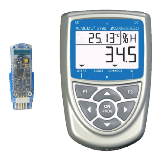
1. Operating controls 1. OPERATING CONTROLS (1) Measuring inputs Suitable for all ALMEMO ® sensors (except D7 sensors) Humidity sensor (option RHA) (3) DC connector 5 to 12 V and USB (ZA 19019-DKU5) (4) LCD (a) Function (b) Measuring point, 2nd measured value Function information (c) Units for 2nd measured value (d) Units for 1st measured value... -
Page 3: Table Of Contents
Table of contents 2. TABLE OF CONTENTS 1. OPERATING CONTROLS................2 3. GENERAL....................5 3.1 Warranty....................5 3.2 Standard delivery................6 3.3 Waste disposal...................6 4. SAFETY INSTRUCTIONS................7 4.1 Special notes on use................8 4.2 Handling batteries / rechargeable batteries correctly.....8 5. INTRODUCTION..................9 5.1 Functions.................... 9 5.1.1 Sensor programming..............10 5.1.2 Process control................10 6. - Page 4 2. Table of contents 13.2 Device locking................24 13.3 Atmospheric pressure compensation..........24 14. WIRELESS TRANSMISSION TO DATA LOGGER........25 15. TROUBLE-SHOOTING................25 16. ANNEX...................... 27 16.1 Technical data.................27 16.2 Product overview................28 16.3 Index....................29 16.4 Your contact partners..............32 ALMEMO 2790 ®...
-
Page 5: General
General 3. GENERAL We should like to congratulate you on your purchase of this new and innovati- ve ALMEMO ® Bluetooth sensor equipment. The wireless system in particular stands out by virtue of its excellent specifications. Thanks to its power ampli- fier and active antenna it provides an especially wide operating range (up to 1000 meters free field). -
Page 6: Standard Delivery
3. General 3.2 Standard delivery When you unpack the device please check carefully for any signs of transport damage and ensure that delivery is complete. Wireless measuring instrument ALMEMO ® 2790-BTFM with three Ni-MH rechargeable batteries Bluetooth sensor module ZA 1729-BTFS These operating instructions ALMEMO ®... -
Page 7: Safety Instructions
Safety instructions 4. SAFETY INSTRUCTIONS DANGER Danger to life and limb, risk of damage to equipment Before starting to operate the device, please read the instructi- ons carefully. Please ensure that you comply with all general safety advice and the special safety instructions included in other chapters. Such risks may occur in the following circumstances: •... -
Page 8: Special Notes On Use
4. Safety instructions 4.1 Special notes on use If the device is brought into the work-room from a cold environment • there is a risk that condensation might form on the electronics. In measuring operations involving thermocouples pronounced changes in temperature may cause substantial measuring errors. -
Page 9: Introduction
5. INTRODUCTION The ALMEMO ® 2790 series is a new member in our family of unique measuring devices - all equipped with Ahlborn's patented ALMEMO ® plug system. These systems incorporate a wireless Bluetooth module and, via the Bluetooth sensor... -
Page 10: Sensor Programming
5. Introduction 5.1.1 Sensor programming The measuring channels are programmed, completely and automatically, via the ALMEMO plugs; they are ready-to-operate immediately. However, via in- ® terface cable ZA1919-DKUx the user can still add to or modify the program- ming. (see Man. 6.3) Or, alternatively, the sensors can be programmed on the ALMEMO ®... -
Page 11: Putting Into Service
Putting into service 6. PUTTING INTO SERVICE 1. Plug wireless sensor module ZA1729-BTFS into a sensor socket on the ALMEMO ® measuring instrument or data logger and switch the device ON. 2. Connect the sensor at socket M0 (1) on the 2790 device see 9. 3. -
Page 12: Operation Using Standard Batteries
7. Power supply current consumption of 8 mA is approx. 230 hours. In sleep mode with a cycle of 1 minute it should be possible per battery charge to perform measuring ope- rations for approx. 390 hours. By extending this cycle to e.g. 1 hour, this time can be increased to approx. -
Page 13: External Dc Voltage Supply
External DC voltage supply 7.3 External DC voltage supply The DC socket (3) can also be used to connect another DC voltage, 6 to 30 V (minimum 200 mA). It can be connected using ALMEMO ® plug ZA1000-FSV. If, however, the power supply has to be electrically isolated from the transducers, then electrically isolated supply cable ZA 2690-UK must be used. -
Page 14: Connecting Sensors
8. Pairing alternate in the wireless measuring instrument display. The components have been successfully paired. 5. Switch the wireless measuring instrument OFF again by pressing and holding down the ON PROG key (5); the sensor module can now be withdrawn from so- cket M0. -
Page 15: Potential Separation
Measuring inputs und additional channels With option RHA the measuring instrument also incorporates a digital sensor for temperature, humidity, and atmospheric pressure (2), occupying channels M01 to M31. However, in wireless transmission to a subsequent linked device, only four channels can be transmitted, normally the first four (M00 to M30 or M00 to M11). -
Page 16: Display And Keypad
10. Display and keypad 10. DISPLAY AND KEYPAD 10.1 Display The display (4) on measuring instruments ALMEMO ® 2790 is a two-row LCD arrangement; this comprises 5 x 7-segment digits (e), 2 x 16-segment digits (d) depicting the measured value, 4½ x 7-segment digits (b) depicting various measuring functions (a), and four arrows (f) depicting the operating status. -
Page 17: Keypad
Display Special operating states and faults Segment test for display: This is performed automatically each time the device is switched on. Supply voltage: (s. 11.1) Display after segment test Below 3.6 V: LOBAT arrow lights up CONNECT arrow lights up Wireless link established: Measuring with wireless transmission: START arrow lights up... -
Page 18: Measuring Operations
10. Display and keypad Function: To switch the device ON: (s. 7.5) ON PROG To switch the device OFF press and hold down ON PROG To select measuring points: (s. 11.1.1) ▲ ▼ To start measuring operation and wireless transmission To access the programming functions . - Page 19 Measured value Deactivating and reactivating measuring channels Since only 4 of the maximum 8 measuring channels (option RH) can be transmitted over a wireless link, individual channels can be ex- cluded from data transmission in order to prio- ritize those further back in the queue. In the display a channel thus deactivated is followed by two dashes.
-
Page 20: Measuring Quantities And Ranges
11. Measuring operations 11.1.2 Measuring quantities and ranges Whenever there is a channel switchover or sensor breakage the measuring range abbreviation appears in the display. The following table lists all the measuring ranges possible. Sensors Sensor / plug Measuring range Unit Abbrevi- ation °C... - Page 21 Measured value Sensors Sensor / plug Measuring range Unit Abbrevi- ation Dynamic pressure, 40 m/s L840 FD A612-M1 0.50... 40.00 with TC and PC Dynamic pressure, 90 m/s FD A612-M6 1.00... 90.00 L890 with TC and PC Rel. atm. humidity, capacitive °orH FH A646 0.0...
-
Page 22: Dual Display
11. Measuring operations 11.1.3 Dual display On all double-function sensors incorporating a temperature sensor on the first channel the temperature value can be displayed at the same time in the function field. Select 2nd channel, To activate the temperature display press and hold down key ▲... -
Page 23: Cycle
Device configuration after the other; the main field should show the respective value currently set. To switch through the possible parameters one after the other press key: . . . Cycle hh:nn Time Format hh:mm OO:O5 Keypad locking (locking code): s. 13.2 OOOO Atmospheric pressure for measured: s. -
Page 24: Device Locking
13. Device configuration In sleep mode the function field displays ab- breviation ´SLP´; in this status the device can no longer be operated. To quit sleep mode and terminate a measu- ring operation the device must be switched ON again by pressing key 13.2 Device locking Measured data acquisition can be locked by means of a password and thus protected... -
Page 25: Wireless Transmission To Data Logger
Atmospheric pressure compensation This can be programmed to any measuring channel (command B86, see Man. 6.3.3) and, with abbreviation '*P' in the designation, can even be forwarded for compensation purposes to the next device. (see Man. 6.3.6) The status of at- mospheric pressure compensation is displayed both in the atmospheric pressure function and, for appropriate measured values, in the function field. - Page 26 15. Trouble-shooting Error: Data transmission over the wireless link does not function. Does the symbol ´ ´ on the device light up ? CONNECT Does the yellow LED on the module light up ? Remedy: Start measuring operation by pressing key Inside a building attenuation may be too high;...
-
Page 27: Annex
Annex 16. ANNEX 16.1 Technical data Measuring inputs one ALMEMO ® socket for all ALMEMO ® sensors Measuring channels 4 channels for double sensors, function channels A/D converter Delta - sigma, 16-bit, 2.5 / 10 mops, amplification 1 to 100 Sensor power supply 6 / 9 / 12 V as required, max 150 mA Option OA2790-RHA... -
Page 28: Product Overview
Wireless measuring instrument ALMEMO ® 2790-BTFM 1 measuring input , 2-row LCD, 7 keys, Bluetooth module, rechargeable batteries, DC socket for mains adapter MA2790BTFV Bluetooth wireless sensor module ZA1729BTFS for ALMEMO ® measuring instruments Options Integrated digital sensor for temp., humidity, and atm. pressure... -
Page 29: Index
Index 16.3 Index abbreviation appears..................20 Accessories..................... 28 additional channels..................14 After-sales service................... 32 Ambient atm. humidity..................27 Ambient atmospheric humidity.................27 atmospheric pressure..................24 Atmospheric pressure compensation............21, 24 batteries......................8 Battery voltage....................18 Bluetooth......................28 Bluetooth sensor module.................27 channel assignment..................15 channel numbering..................25 Checksum error.................... - Page 30 16. Annex Humidity sensor....................2 Interface......................22 Introduction......................9 keypad......................16 Keypad......................17 lithium batteries....................12 LOBAT....................2, 12, 17f. locking code....................24 Main field......................16 mains adapter....................12 Mains adapter..................11, 27f. Mains operation....................12 maximum value....................22 Measured value....................18 measuring functions..................16 Measuring inputs..................14, 27 measuring operation start................23 Measuring operations..................18 Measuring quantities and ranges..............20...
- Page 31 Index Process control....................10 Product overview..................... 28 Protocol......................28 psychrometric....................24 Putting into service..................11 rechargeable batteries..................8 rechargeable Ni-MH batteries................28 reinitialization....................13 replace used batteries..................12 Reset....................... 13 Rubber guard....................28 Safety instructions.....................7 sea level......................24 segment test....................18 Selecting a measuring point................18 Sensor breakage.....................
-
Page 32: Your Contact Partners
16. Annex 16.4 Your contact partners Ahlborn Mess- und Regelungstechnik GmbH, Eichenfeldstraße 1-3, D-83607 Holzkirchen, Tel. +49(0)8024/3007-0, Fax +49(0)8024/300710 Internet: http://www.ahlborn.com, email: amr@ahlborn.com After-sales service / Hot-line Florian Plessner, Telephone +49(0)8024/3007-38 We take every possible care but the risk of inaccuracy can never be altogether excluded.
Need help?
Do you have a question about the MA2790BTFV and is the answer not in the manual?
Questions and answers