
Related Manuals for Extron electronics MTP/HDMI U R


Summary of Contents for Extron electronics MTP/HDMI U R
- Page 1 User Guide TWISTED PAIR MTP/HDMI U R MTP Twisted Pair Universal Receiver 68-1727-01 Rev. C 08 10...
- Page 2 Precautions Safety Instructions • English Warning Power sources • This equipment should be operated only from the power source indicated on the product. This This symbol is intended to alert the user of important operating and maintenance equipment is intended to be used with a main power system with a grounded (neutral) conductor. The (servicing) instructions in the literature provided with the equipment.
- Page 3 CAUTION: A Caution warns of things or actions that might damage the equipment. WARNING: A Warning warns of things or actions that might cause injury, death, or other severe consequences. Copyright © 2010 Extron Electronics. All rights reserved. Trademarks All trademarks mentioned in this guide are the properties of their respective owners.
-
Page 5: Table Of Contents
Contents Introduction............1 Reference Information........13 Part Numbers and Accessories ......16 MTP/HDMI U R Description ......... 1 Included Parts ..........16 Optional Parts ..........16 Cabling..............3 Rear Panel Cabling ..........3 Mounting............... 17 Wiring Connectors ..........7 Wall Mounting ..........17 Digital Connector Pin Connector ..... - Page 6 MTP/HDMI U R • Contents...
-
Page 7: Introduction
The receivers auto detect video formats and RS-232/audio signals, enabling the signal to be output on the appropriate rear panel connector. The MTP/HDMI U R is part of the Extron line of twisted pair transmitters, receivers, and associated video accessories. - Page 8 The MTP/HDMI U R ships with an external desktop 12 V, 1 A power supply that accepts 100 to 240 VAC, 50 Hz or 60 Hz input. A summary table of the MTP/HDMI U R connectivity is shown below. Feature Connectivity Digital.output...
-
Page 9: Cabling
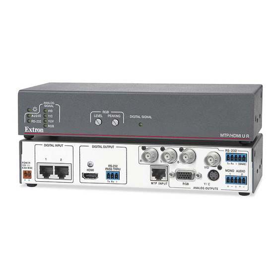
This section describes how to connect cables to the MTP/HDMI U R. • Rear Panel Cabling • Wiring Connectors Rear Panel Cabling The illustration below shows the rear panel features of the MTP/HDMI U R. DIGITAL OUTPUT DIGITAL INPUT RS-232 Tx Rx SPARE... - Page 10 A/V cable to link the transmitter and receiver. Use of this cable will cause problems with the digital signal input side of the MTP/HDMI U R receiver. It is important to ensure the cable from output 1 on the transmitter is connected to input 1 on the receiver.
- Page 11 HDMI Digital signal output — The MTP/HDMI U R outputs a digital HDMI signal "HDMI Connector Pin through this female HDMI connector. See the Assignments" section, for pin wiring details. RS-232 Control Pass-thru connector — Connect a serial communications port to this 3.5 mm, 3-pole captive screw connector for bidirectional RS-232 communication (digital...
- Page 12 Wiring" section, to wire the connector. See the NOTE: The RS-232 port configuration by default is bidirectional RS-232 on the digital input. The MTP/HDMI U R can be configured via the jumpers on the “Setting the Jumpers” section, for details. main board. See the The MTP/HDMI U R DOES NOT support IR control on the analog side.
-
Page 13: Wiring Connectors
DDC / CEC shield shield Ground TMDS data 1- TMDS clock- +5 V power * CEC control on pin 13 is a proprietary Hot plug detect usage, not the industry standard. Figure 9. HDMI Connectors MTP/HDMI U R • Cabling... -
Page 14: Control Connector Wiring
NOTE: Do not tin the wires before installing them in the connector. Tinned wires are not as secure and could be pulled out. MTP/HDMI U R • Cabling... -
Page 15: Operation
Operation This section of the guide discusses the operation of the MTP/HDMI U R and cover the following points: • Front Panel Overview • Level and Peaking • Signal Detection • Setting the Jumpers Front Panel Overview ANALOG SIGNAL LEVEL... -
Page 16: Level And Peaking
Disconnect the oscilloscope or monitor, and the test generator, connected in step 1. Signal Detection The MTP/HDMI U R is capable of auto signal detection and automatically routes the input signal to the appropriate output connector. When the signal is detected on the analog input, the applicable front panel LED (VID, Y/C, YUV, or RGB) lights green to indicate the video type. -
Page 17: Setting The Jumpers
JMP1 should be set to unidirectional when an MTP DA is installed as part of the system to avoid any RS-232/audio detection issues. When an MTP/HDMI U R series receiver is used with an MTPX matrix switcher, JMP1 should be set to unidirectional for transmitter to receiver communication, otherwise it should be set to bidirectional when using the RS-232 output insert connections on the switcher. -
Page 18: Setting Jmp2 And Jmp3 To Positive Vertical And/Or Horizontal Sync Polarity
Horizontal and vertical sync polarity can be set by configuring the internal jumpers on the MTP/HDMI U R main board. The default setting is negative sync (H- V-), and can be changed by resetting the position of the jumpers as follows: If the unit is not already open, follow steps 1 and 2 in the “Setting JMP1 for RS-232... -
Page 19: Reference Information
NOTE: The transmission distance varies greatly depending on the signal resolution and on the type of cable, graphics card, and display used in the system. Formats ........RGB and YCbCr digital video Standards ........ DVI 1.0, HDMI 1.2 MTP/HDMI U R • Reference Information... -
Page 20: Video Input
Audio output — from MTP input Number/signal type ......2 mono, balanced/unbalanced Connectors ........(1) 3.5 mm captive screw connector, 5 pole Impedance ........50 ohms unbalanced, 100 ohms balanced Gain error ........±1 dB channel to channel MTP/HDMI U R • Reference Information... - Page 21 EMI/EMC ......... CE, C-tick, FCC Class A, ICES, VCCI MTBF ..........30,000 hours Warranty ........3 years parts and labor NOTE: All nominal levels are at ±10%. NOTE: Specifications are subject to change without notice. MTP/HDMI U R • Reference Information...
-
Page 22: Part Numbers And Accessories
External, 12 VDC, 1 A power supply PS 1210 C 70-775-01 3.5 mm, 3-pole captive screw connector for RS-232 connections IEC power cord (1) Setup Guide - MTP/HDMI U R Optional Parts Description Part Number RSU 129 (1U, 9.5" deep rack shelf kit) 60-190-01 RSB 129 (1U, 9.5"... -
Page 23: Mounting
Through-desk Mounting Wall Mounting The MTP/HDMI U R can be mounted on a wall, using the optional Extron WMK 150 wall mounting kit. This allows the unit to be concealed close to wall-mounted flat screen monitors. To mount the unit on the wall, follow the instructions provided with the WMK 150 kit. -
Page 24: Rack Mounting
(part # 70-077-01) by following the instructions provided with the MBU 125 kit. Through-desk Mounting Mount the unit through a desk or podium using the optional Extron MBD 129 through-desk mounting kit (part # 70-077-02) following the instructions provided with the MBD 129 kit. MTP/HDMI U R • Mounting... - Page 25 Extron Electronics makes no further warranties either expressed or implied with respect to the product and its quality, performance, merchantability, or fitness for any particular use. In no event will Extron Electronics be liable for direct, indirect, or consequential damages resulting from any defect in this product even if Extron Electronics has been advised of such damage.
Need help?
Do you have a question about the MTP/HDMI U R and is the answer not in the manual?
Questions and answers