
Related Manuals for Extron electronics MTP AV Series


Summary of Contents for Extron electronics MTP AV Series
- Page 1 User Guide Twisted Pair MTP AV Series Video and Audio Twisted Pair Transmitters and Receivers 68-732-01 Rev. J 04 13...
- Page 2 Safety Instructions • English Chinese Simplified (简体中文) 警告: 产品上的这个标志意在警告用户该产品机壳内有暴露的危险 WARNING: This symbol, when used on the product, is intended to alert the user of the presence of uninsulated dangerous voltage within 电压, 有触电危险。 the product’s enclosure that may present a risk of electric shock. 注...
- Page 3 Compliance Guide” on the Extron website. Copyright © 2013 Extron Electronics. All rights reserved. Trademarks All trademarks mentioned in this guide are the properties of their respective owners. The following registered trademarks , registered service marks...
- Page 4 Conventions Used in this Guide Notifications The following notifications are used in this guide: CAUTION: Electrical Shock that may result in injury. Use tools with care to prevent injury. ATTENTION: Attention indicates a situation that may damage or destroy the product or associated equipment.
-
Page 5: Table Of Contents
Transmitter Input Connections ......7 Transmitter and Receiver Throughput Connections ..........9 Power Connection (All Models) ..... 11 Receiver Output Connections ....... 12 Operation ............14 Front Panel Features ......... 14 Troubleshooting — Skew Delay Compensation . 14 MTP AV Series • Contents... - Page 6 MTP AV Series • Contents...
-
Page 7: Introduction
The MTPs ship with external desktop 12 V power supplies that accept 100 to 240 VAC, 50-60 Hz input. If jumpers are repositioned from the default settings, a single power supply can power both units if there is less than 200 feet (61 meters) of STP/UTP/FTP cable between the two. MTP AV Series • Introduction... -
Page 8: Tp Cable Advantages
• The audio output of any transmitter (captive screw or RCA) is compatible with any audio receiver in the MTP family described in this guide if the transmitter and receiver jumper configuration are compatible. MTP AV Series • Introduction... -
Page 9: Installation
70-361-02, -03 70-361-22 Old Generation New Generation Receiver Part Number Part Number MTP R SV A 60-541-22 60-541-52 MTP R SV A RCA 60-541-32 60-541-62 MTP R AV 60-541-21 60-541-51 MTP R AV RCA 60-541-31 60-541-61 MTP AV Series • Installation... -
Page 10: Setting The Jumpers On New Generation Non Aap Models
Pull the audio board back until the audio connectors clear the back of the unit and lift the board out of the way. Remove and retain these screws. Transmitter Front Panel Receiver Front Panel Transmitter Rear Panel Receiver Rear Panel Figure 2. Removing the Audio Board MTP AV Series • Installation... - Page 11 RCA audio connectors. • Both jumpers (video and audio) must be set to either mono or stereo for it to pass audio and video successfully. Replace the cover and the four screws (removed in step 1). MTP AV Series • Installation...
-
Page 12: Setting The Jumpers On Aap Transmitters
Feed the RJ-45 connector through the hole in the cover marked “Output” and replace the cover. Secure the cover in place with the two screws (removed in step 1). ATTENTION: Ensure that the TP cable is not pinched when you reinstall the cover. MTP AV Series • Installation... -
Page 13: Panel Features And Connections
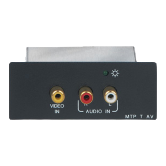
NOTE: High impedance is generally over 800 ohms. Ring Sleeve Sleeves Sleeve Do not tin the wires! Ring Unbalanced Stereo Input Balanced Stereo Input Captive Screw Input Connector Wiring Figure 9. MTP AV Series • Installation... - Page 14 Audio input RCA connectors (RCA and AAP models) — Connect an unbalanced stereo audio source to these L(eft) and R(ight) RCA connectors (see figure 11). Tip (Signal) Right Channel (Red Jacket) Sleeve (Gnd ) Left Channel (White Jacket) Figure 11. RCA Audio Connectors MTP AV Series • Installation...
-
Page 15: Transmitter And Receiver Throughput Connections
RJ-45 female connector on the transmitter. On the MTP T AV AAP, the connector is at the end of a short pigtail. Connect the free end of the same TP cable from the transmitter to the RJ-45 female connector on the receiver. MTP AV Series • Installation... - Page 16 The green, brown, and blue pairs of this cable have virtually identical lengths and should be used to transmit the video signals. • The orange pair of this cable has a different length and should not be used to transmit the video signals. MTP AV Series • Installation...
-
Page 17: Power Connection (All Models)
Do not tin the stripped power supply leads before installing the captive screw or direct insertion connector. Tinned wires could be pulled out because they are not as secure in the captive screw and direct insertion connectors. MTP AV Series • Installation... -
Page 18: Receiver Output Connections
Figure 16. Output Connector Wiring S-video connector (SV models) — Connect an S-video device to this 4-pin mini DIN connector. Composite video connector (AV models) — Connect a composite video device to this BNC connector. MTP AV Series • Installation... - Page 19 Shorter bare wires are not as secure in the direct insertion connectors and could be pulled out. RCA audio connectors (RCA models) — Connect a stereo audio device to these L(eft) and R(ight) RCA connectors. MTP AV Series • Installation...
-
Page 20: Operation
Add an S-video-to-BNC adapter and a skew compensation cable equal to the length of • pair skew to the receiver output. Install an S-video-to-BNC adapter and an SEQ 100 15HD Skew Equalizer on the • receiver video output and adjust the skew for the leading video image. MTP AV Series • Operation... -
Page 21: Reference Information
Tabletop Use (All Except AAP Models) The non-AAP MTPs come with four self-adhesive rubber feet. Attach one to each of the four bottom corners. Set the MTP on a horizontal surface. MTP AV Series • Reference Information... -
Page 22: Frame Mounting (Aap Models)
NOTE: The rear panel MTP connections will be inaccessible after installation. Make all connections (see “Transmitter and Receiver Throughput Connections” on page 9) and test the twisted pair system (apply a video source and observe that transmitted video is correctly displayed) before installing the transmitter. MTP AV Series • Reference Information... - Page 23 Extron Electronics makes no further warranties either expressed or implied with respect to the product and its quality, performance, merchantability, or fitness for any particular use. In no event will Extron Electronics be liable for direct, indirect, or consequential damages resulting from any defect in this product even if Extron Electronics has been advised of such damage.
Need help?
Do you have a question about the MTP AV Series and is the answer not in the manual?
Questions and answers