Advertisement
Quick Links
MTP/HDMIоUоRо•оSetupоGuide
ANALOG
SIGNAL
RGB
VID
LEVEL
PEAKING
AUDIO
Y/C
RS-232
YUV
RGB
DIGITAL OUTPUT
DIGITAL INPUT
1
2
POWER
12V
RS-232
HDMI
0.8A MAX
PASS THRU
Tx Rx
Installation
Step 1 — Mounting
Turn off or disconnect all equipment power sources and mount the device as required.
Step 2 — Connect input
Connect up to two twisted pair cables from an HDMI 201 Tx to the RJ-45 connectors labeled Digital Inputs 1 and 2. Connect
an MTP transmitter, a switcher, or a Distribution Amplifier (DA) to the MTP input.
CAUTION: Do not connect the twisted pair input cables to a LAN port, or connect a LAN cable to the digital or MTP ports.
Step 3 — Connect outputs and RS-232 control devices
Analog video— Connect output devices to the Analog Output connectors as shown below.
о о
NOTE: The analog outputs are the signals generated on the MTP input. The signal is detected and sent to the
appropriate analog output.
Component Video –
Connect to these 3 BNCs.
R-Y
Y
RGBHV and RGBS –
Connect to this VGA
connector.
Figureо1.оAnalog Outputs, and Audio and RS-232 Wiring
Audio — Connect a suitable audio device to the 5-pole captive screw audio output connector
о о
for a balanced or unbalanced, dual mono audio signal. Wire connector as shown in figure 1.
NOTE: The audio signal is detected on the MTP input, and then is distributed to the
audio connector for output.
Audio is not available from the digital side on this connector.
Control device (analog side) — Connect a serial communications port to the upper
о о
3.5 mm, 5-pole captive screw connector for bidirectional or unidirectional RS-232
communication. Wire the connector as shown in figure 1.
NOTE: The RS-232 port configuration (analog side) as unidirectional or bidirectional is
controlled by the internal jumper settings (see "Setting the Jumpers", page 2).
Digital video — Connect a suitable output to the female HDMI output.
о о
Control device (digital side) — Connect a serial communications port to the
о о
3.5 mm, 3-pole captive screw connector for pass-through RS-232 bidirectional
communication. Wire the connector as shown in figure 2.
Step 4 — Connect power
Wire a standard IEC power cord from a 100 to 240 VAC, 50 - 60 Hz power source into the
12 VDC, 0.8 A, 2-pole captive screw connector, as shown in figure 3.
When power is applied the front panel power LED lights.
DIGITAL SIGNAL
MTP/HDMI U R
RS-232
R-Y
B-Y
Tx Rx
SPARE
Y
VID
MONO AUDIO
1
2
Y/C
RGB
MTP INPUT
ANALOG OUTPUTS
Composite Video –
RS-232 Control (Analog Side) –
Connect to this captive screw
Connect to this BNC.
connector.
RS-232
B-Y
Tx Rx
SPARE
VID
MONO AUDIO
1
2
Y/C
RGB
ANALOG OUTPUTS
S-video – Connect to
Mono Audio – Connect
this mini DIN connector.
to this captive screw
connector.
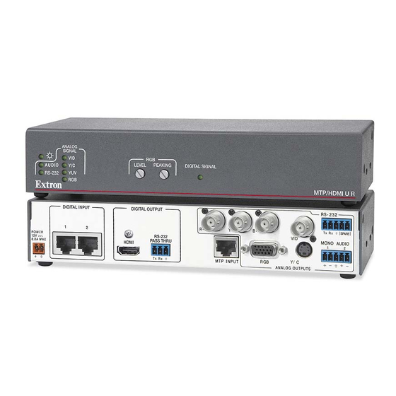
The Extron
MTP/HDMI U R is a twisted
®
pair and HDMI universal receiver for
analog and digital signals, and is
compatible with MTP and HDMI 201 Tx
transmitters. For full details, refer to the
MTP/HDMI U R User Guide, available
www.extron.com
online at
Wire the RS-232 connector as shown below.
Connected RS-232 Device Pins MTP/HDMI U R
Receive
Transmit
Ground
Mono output 1
NO GROUND.
Sleeve(s)
Mono output 2
NO GROUND.
Unbalanced Output
Mono output 1+
Mono output 1-
Sleeve(s)
Mono output 2+
Mono output 2-
Balanced Output
Wire the audio connector as shown above.
.
Pins
Tx
Rx
Gnd
Spare
Spare
Do not tin
the wires!
MTP/HDMI
Pass-thru
Connected RS-232
Figureо2.оDigital RS-232 Wiring
Smooth
A
Power Supply
Output Cord
SECTION A–A
Figureо3.оPower Connector Wiring
RS-232
Tx Rx
Rx Tx Grnd
Device Pins
Ridges
A
2-pole Captive
Screw
Connector
Tie Wrap
3
1
Advertisement

Related Manuals for Extron electronics MTP/HDMI U R


Summary of Contents for Extron electronics MTP/HDMI U R
- Page 1 Wire the RS-232 connector as shown below. Composite Video – RS-232 Control (Analog Side) – Component Video – Connect to this captive screw Connect to this BNC. Connect to these 3 BNCs. Connected RS-232 Device Pins MTP/HDMI U R connector. Pins Receive Transmit RS-232 Ground...
- Page 2 SettingоJMP2оandоJMP3оtoоpositiveоverticalоand/orоhorizontalоsyncоpolarity Horizontal and vertical sync polarity can be set by configuring the internal jumpers on the MTP/HDMI U R main board. The default setting is negative sync (H- V-), and can be changed by resetting the position of the jumpers as follows: Follow steps 1 and 2 above 1.о...
Need help?
Do you have a question about the MTP/HDMI U R and is the answer not in the manual?
Questions and answers