
Related Manuals for Extron electronics MTP T SV A


Summary of Contents for Extron electronics MTP T SV A
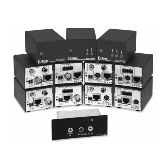
- Page 1 User Guide Twisted Pair MTP AV Series Video and Audio Twisted Pair Transmitters and Receivers 68-732-01 Rev. I 12 11...
- Page 2 Safety Instructions • English Warning Power sources • This equipment should be operated only from the power source indicated on the product. This This symbol is intended to alert the user of important operating and mainte- equipment is intended to be used with a main power system with a grounded (neutral) conductor. The third nance (servicing) instructions in the literature provided with the equipment.
- Page 3 FCC Class A Notice This equipment has been tested and found to comply with the limits for a Class A digital device, pursuant to part 15 of the FCC Rules. Operation is subject to the following two conditions: This device may not cause harmful interference. This device must accept any interference received, including interference that may cause undesired operation.
- Page 4 TIP: A tip provides a suggestion to make working with the application easier. WARNING: A warning warns of things or actions that might cause injury, death, or other severe consequences. Copyright © 2011 Extron Electronics. All rights reserved. Trademarks All trademarks mentioned in this guide are the properties of their respective owners.
-
Page 5: Table Of Contents
Contents Introduction Reference Information ............1 ........15 About the MTP Transmitters and Receivers ..1 Specifications ............ 15 TP Cable Advantages .......... 2 Part Numbers ............ 18 Transmission Distance ......... 2 MTP Transmitters .......... 18 MTP Receivers ..........18 AAP Accessories .......... - Page 6 MTP AV Series • Contents...
-
Page 7: Introduction
Introduction This section introduces the MTP transmitters and receivers. Topics discussed in this section are: About the MTP Transmitters and Receivers • • TP Cable Advantages Transmission Distance • About the MTP Transmitters and Receivers The Extron MTP transmitters and receivers provide a system for long-distance distribution of NTSC, PAL, or SECAM video and audio. -
Page 8: Tp Cable Advantages
Composite Audio S-Video (Captive Video (RCA) Mounted Transmitters Screw) MTP T SV A • • MTP T SV A RCA • • MTP T AV • • MTP T AV RCA • • MTP T AV AAP • • •... -
Page 9: Installation
Only the new generation units have these jumpers. Old Generation New Generation Transmitter Part Number Part Number MTP T SV A 60-540-22 60-540-52 MTP T SV A RCA 60-540-32 60-540-62 MTP T AV 60-540-21 60-540-51 MTP T AV RCA 60-540-31 60-540-61... -
Page 10: Setting The Jumpers On New Generation Non Aap Models
Setting the Jumpers on New Generation Non AAP Models Remove and retain the four screws (two on each side of the unit) that secure the cover to the MTP (see figure 1). Figure 1. Removing the MTP Cover For the receiver, slide the cover slightly forward to clear the front panel adjustment knobs. - Page 11 Locate the jumper blocks (see figure 3) on the video board. Shift the jumper to the alternate location. Mono (default jumper position) Compatible with new model transmitter/receivers. Cannot remotely power transmitter/receiver Transmitter Front Panel Receiver Front Panel Transmitter Receiver Rear Panel Rear Panel Stereo Compatible with old model transmitter/receivers.
-
Page 12: Setting The Jumpers On Aap Transmitters
step Replace the cover and the four screws (removed in Setting the Jumpers on AAP Transmitters Remove and retain the two screws that secure the back cover to the MTP (see figure 5). 1. Remove these screws. 2. Carefully pull the RJ-45 connector through this hole. -
Page 13: Panel Features And Connections
(female RCA on the MTP T AV AAP, female BNC on all other models). Audio input captive screw connector (MTP T SV A, MTP T AV) — Connect a balanced or unbalanced audio input to this 3.5 mm, 5-pole captive screw connector. - Page 14 CAUTIONS: • The length of the exposed (stripped) portion of the copper wires is important. The ideal length is 3/16 inches (5 mm). Longer bare wires can short together. Shorter bare wires are not as secure in the direct insertion connectors and could be pulled out. •...
-
Page 15: Transmitter And Receiver Throughput Connections
MTP Transmitters MTP Receivers INPUT OUTPUT S-VIDEO S-VIDEO OUTPUT INPUT 0.5a MAX 0.5a MTP R SV A RCA MTP T SV A RCA INPUT OUTPUT VIDEO VIDEO OUTPUT INPUT 0.5a MAX 0.5a MAX MTP R AV MTP T AV Figure 12. -
Page 16: Tp Cable Termination
TP cable termination Figure 13 details the recommended termination of TP cables with RJ-45 connectors in accordance with the TIA/EIA T 568A or TIA/EIA T 568B wiring standards. You can use either standard, but ensure that you use the same standard on both cable ends. WARNING: Damage may occur to the unit if TP cables are miswired as crossover cables. -
Page 17: Power Connection (All Models)
S-VIDEO S-VIDEO OUTPUT INPUT 0.5a MAX 0.5a MAX MTP R SV A RCA MTP T SV A RCA MTP AAP Transmitters VIDEO AUDIO IN MTP T AV Figure 14. Power Connections and Indicators Power connector — Plug the external 12 VDC power supply into this 2-pole captive screw connector on both the transmitter and the receiver. -
Page 18: Receiver Output Connections
CAUTIONS: • Power supply voltage polarity is critical. Incorrect voltage polarity can damage the power supply and the MTP. Identify the power cord negative figure 15 lead by the ridges on the side of the cord (see • The length of the exposed (stripped) copper wires is important. The ideal length is 3/16 inches (5 mm). - Page 19 Captive screw audio connector (MTP R SV A, MTP R AV) — Connect a balanced or unbalanced audio device, such as an audio amplifier, to this 3.5 mm, 5-pole captive screw connector (see figure 17 to properly wire the output connector). Sleeve Ring Sleeve (s)
-
Page 20: Operation
Operation This section describes: • Front Panel Features Troubleshooting — Skew Delay Compensation • Front Panel Features MTP R Composite Video MTP R S-video Receiver Receiver Front Panel Front Panel Figure 18. MTP Receiver Front Panels Power LED — When lit, this LED indicates power is applied to the MTP. Sharpness —... -
Page 21: Reference Information
Reference Information This section provides information on: • Specifications Part Numbers • • Mounting Options Specifications Video Gain ..........Unity Differential phase error ....<1.0° at 3.58 MHz and 4.43 MHz Differential gain error ....<1.0% at 3.58 MHz and 4.43 MHz Video input Number/signal type MTP T AV Series .... -
Page 22: Audio Input
MTP R Series ...... 1 set of proprietary analog signals Connectors MTP T AV, MTP T SV A ..(1) 3.5 mm captive screw connector, 5 pole MTP T AV/SV A RCA, MTP T AAP 1 pair of RCA female MTP R Series ...... - Page 23 General Recommended cable type ....CAT5/5e/6 (shielded or unshielded) External power supply ....100 VAC to 240 VAC, 50-Hz, external; to 12 VDC, 1.0 A, regulated Power input requirements ....12 VDC, 0.2 A NOTES: • If the distance between the transmitter and receiver is less than 500 feet (150 m) and if the internal jumper is in setting 2, you can connect a power supply to only one device in a transmitter/receiver pair.
-
Page 24: Part Numbers
Part Numbers MTP Transmitters Description Part Numbers MTP T SV A 60-540-52 MTP T SV A RCA 60-540-62 MTP T AV 60-540-51 MTP T AV RCA 60-540-61 MTP T AV AAP (black) 70-361-22 MTP Receivers Description Part Numbers MTP R SV A... -
Page 25: Cables And Connectors
Cables and Connectors NOTE: Enhanced Skew-Free AV UTP cables are not recommended for Ethernet/LAN applications. Enhanced Skew-Free AV Cable Part Numbers Enhanced Skew-Free AV UTP (various lengths) 26-569-xx Enhanced Skew-Free AV UTP, bulk 22-141-03 Plenum Enhanced Skew-Free AV UTP, bulk 22-142-03 RJ-45 Connector Part Numbers... -
Page 26: Mounting Options
Mounting Options NOTE: For Rack, Furniture, or Projector Mount installation, see the installation card that comes with the kit. UL Requirements The following Underwriters Laboratories (UL) requirements pertain to the installation of the MTP transmitter or receiver into a rack. Elevated operating ambient —... -
Page 27: Extron Warranty
Extron Electronics makes no further warranties either expressed or implied with respect to the product and its quality, performance, merchantability, or fitness for any particular use. In no event will Extron Electronics be liable for direct, indirect, or consequential damages resulting from any defect in this product even if Extron Electronics has been advised of such damage.
Need help?
Do you have a question about the MTP T SV A and is the answer not in the manual?
Questions and answers