Table of Contents
Advertisement
Quick Links
Extron USA - West
Extron USA - East
Extron Europe
Headquarters
+800.633.9876
+800.3987.6673
+800.633.9876
Inside USA / Canada Only
Inside Europe Only
Inside USA / Canada Only
+1.919.863.1794
+31.33.453.4040
+1.714.491.1500
+1.919.863.1797 FAX
+31.33.453.4050 FAX
+1.714.491.1517 FAX
© 2009 Extron Electronics. All rights reserved.
Extron Asia
Extron Japan
Extron China
Extron Middle East
+800.7339.8766
+81.3.3511.7655
+400.883.1568
+971.4.2991800
Inside Asia Only
+81.3.3511.7656 FAX
Inside China Only
+971.4.2991880 FAX
+65.6383.4400
+86.21.3760.1568
+65.6383.4664 FAX
+86.21.3760.1566 FAX
User's Manual
Digital Video Transmitter and Receiver
HDMI 201 Tx/Rx
68-1375-01 Rev. C
01 09
Advertisement
Table of Contents

Related Manuals for Extron electronics HDMI 201 Rx


Summary of Contents for Extron electronics HDMI 201 Rx
- Page 1 Extron USA - West Extron USA - East Extron Europe Extron Asia Extron Japan Headquarters +800.633.9876 +800.3987.6673 +800.7339.8766 +81.3.3511.7655 +800.633.9876 Inside USA / Canada Only Inside Europe Only Inside Asia Only +81.3.3511.7656 FAX Inside USA / Canada Only +1.919.863.1794 +31.33.453.4040 +65.6383.4400 +1.714.491.1500 +1.919.863.1797 FAX...
- Page 2 Safety Instructions • English Warning Power sources • This equipment should be operated only from the power source This symbol is intended to alert the user of important indicated on the product. This equipment is intended to be used with a main power operating and maintenance (servicing) instructions in system with a grounded (neutral) conductor.
- Page 3 安全须知 • 中文 这个符号提示用户该设备用户手册中 有重要的操作和维护说明。 这个符号警告用户该设备机壳内有暴 露的危险电压,有触电危险。 注意 阅读说明书 • 用 户 使 用 该 设 备 前 必 须 阅 读 并 理 解 所 有 安 全 和 使 用 说 明 。 保存说明书 • 用户应保存安全说明书以备将来使 用。 遵守警告 • 用户应遵守产品和用户指南上的所有安 全和操作说明。...
-
Page 4: Table Of Contents
Table of Contents Chapter One • Introduction ... 1-1 About this Manual ... 1-2 About the HDMI 201 Tx/Rx ... 1-2 TP cable advantages ... 1-4 Control communications ... 1-4 Transmission distance ... 1-4 Features ... 1-5 Chapter Two • Installation and Operation Mounting the Tx/Rx ... - Page 5 Table of Contents, cont’d Appendix A • Reference Information Specifications ...A-2 Part Numbers ...A-6 Transmitter/receiver pair part numbers ...A-6 Included parts...A-6 Mounting accessories ...A-7 Cables...A-7 Adapters ...A-8 Decora Template Dimensions ...A-8 All trademarks mentioned in this manual are the properties of their respective owners. HDMI 201 Tx/Rx •...
-
Page 6: About This Manual
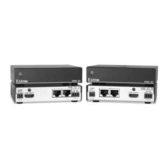
HDMI 201 Tx/Rx • Introduction ™ ) extenders, the RS-232 Control Extron HDMI 201 Rx Receiver -2 32 0 .4 There are two subsets of transmitters and receivers in two different enclosures or form factors: • HDMI 201 Tx/Rx — These units are housed in quarter rack width metal enclosures. -
Page 7: Tp Cable Advantages
Decora form factor. Tx and HDMI 201 Rx [non-Decora] only) — With low profile enclosures, both transmitter models and both receiver models can be discreetly installed in locations such as behind a plasma or LCD flat-panel display. - Page 8 Introduction, cont’d HDMI 201 Tx/Rx Chapter Two Installation and Operation Mounting the Tx/Rx Connections Operation Technical Points for Digital Video and Content Protection Encryption Troubleshooting Application Examples HDMI 201 Tx/Rx • Introduction...
-
Page 9: Mounting The Tx/Rx
Installation and Operation Mounting the Tx/Rx Installation and service must be performed by authorized personnel only. Non-Decora unit mounting The 1" high, quarter rack width HDMI 201 (non-Decora) transmitters and receivers can be placed on a tabletop, mounted on a rack shelf, or mounted under a desk or tabletop. The receiver can be mounted on a projector bracket. -
Page 10: Under-Furniture Mounting
Installation and Operation, cont’d 1U Universal Rack Shelf 1/2 Rack Width Front False Faceplate Both front false faceplates use 2 screws. Use 2 mounting holes on opposite corners. Figure 2-2 — Mounting the transmitter or receiver unit on a standard rack shelf Under-furniture mounting The unit can be mounted under a horizontal surface using an optional MBU 125 under-desk mounting kit (part #70-077-01). -
Page 11: Projector Mounting
Installation and Operation, cont’d Loosely attach the mounting brackets to the transmitter or receiver using the four machine screws and washers supplied with the mounting kit. Hold the transmitter or receiver against the inside of the surface through which it will be mounted. Mark the four screw holes and the table material to be removed on the inside of the surface to which you are mounting the device. - Page 12 Installation and Operation, cont’d The PMK 300 has a hole in the bottom plate that allows the projector pole to be inserted through the center of the plate (figure 2-6), rather than outside of the plate (figure 2-5). To install the PMK 300 in this configuration, slide the bracket up from the bottom of the pole before the projector is installed on the pole.
-
Page 13: Decora Unit Mounting
Installation and Operation, cont’d Assemble the U-bolt and the following parts in the following order (figure 2-8): a. Pass the legs of the U-bolt through the slotted holes on the mount plate flange. b. Place the legs around the projector pole. c. - Page 14 Installation and Operation, cont’d 2.50” [63.5mm] TP Cable 1.51” [38.48mm] (no boot) Captive Screw Connectors TP Cable (no boot) Junction Box 1.85” [47mm] Figure 2-9 — Decora unit depth profile To install a new wall box, perform steps 1 through 9 below. If a suitable wall box is already installed, perform steps 6 through 9 below.
-
Page 15: Final Installation
Installation and Operation, cont’d Final installation After testing and making any adjustments, do the following: At the power outlet, unplug the power supply. One power supply can power both the transmitter and the receiver, so only one unit needs a power supply. Mount the transmitter or receiver into the wall box, and attach the supplied Decora faceplate to the unit, as shown in figure 2-11. - Page 16 Installation and Operation, cont’d HDMI 201 Tx Rear Panel POWER HDMI INPUT 0.4A MAX HDMI 201 A D Tx Rear Panel HDMI 201 A D Tx DO NOT CONNECT TO LAN Figure 2-13 — HDMI 201 Tx rear panel connectors The RS-232 connector can also transmit one-way modulated infrared (IR) signals.
-
Page 17: Receiver Connections
The wall-mountable receiver is in an enclosure that can be mounted in UL standard wall boxes with Decora-style face plates. Figure 2-16 shows the rear panel of both HDMI 201 Rx models. Figure 2-17 shows the front panel of the HDMI 201 A D Rx (Decora) receiver. - Page 18 Installation and Operation, cont’d HDMI 201 A D Rx Front Panel OUTPUT HDMI AUDIO-R RS-232 PASS THRU AUDIO-L Figure 2-17 — HDMI 201 A D Rx front panel connectors DC power input connector — Plug the included external 12 VDC power supply into either this 2-pole connector or the power input connector on the transmitter (item See "Power supply wiring,"...
-
Page 19: Pin Assignments And Wiring
Installation and Operation, cont’d Output Audio — Plug an audio device into this pair, left and right, of female RCA connectors (figure 2-14) for an unbalanced stereo audio signal. Pin assignments and wiring HDMI connector pin assignments Figure 2-19 defines the pinout for the HDMI protocol. HDMI Type A Receptacle Signal... -
Page 20: Power Supply Wiring
Installation and Operation, cont’d Terminating shielded cable The transmitter and receiver pair works with unshielded twisted pair (UTP) or shielded twisted pair (STP) cables; but, to ensure FCC Class A and CE compliance, STP cables are required. The Tx/Rx includes four shielded RJ-45 connectors and a length of self-adhesive shielded tape that you can use to make the STP cables that connect the transmitter and receiver. -
Page 21: Chapter One
Figure 2-26 shows the power indicator on the non-Decora and Decora models. Two units are shown. All transmitter and receiver models have power indicators in the locations shown. HDMI 201 Tx and HDMI 201 Rx Front Panel INPUT HDMI AUDIO-R... -
Page 22: Transmitter Power Indicator
HDMI input. Receiver indicator Power LED — HDMI 201 Rx (non-Decora) — This front panel LED lights green to indicate that the unit is receiving power: HDMI 201 A D Rx (Decora) — This two-color front panel LED lights to indicate signal and power status as follows: Amber —... -
Page 23: Troubleshooting
CONNECT TO LAN HDMI 201 A D Tx Rear Audio System Figure 2-27 — Typical installation HDMI 201 Tx/Rx • Installation and Operation Projector HDMI 201 Rx HDMI OUTPUT RS-232 PASS THRU Tx Rx HDMI 201 Rx Balanced Audio Wiring... -
Page 24: Specifications
TP 2 Modulated IR HDMI 201 A D Tx Figure 2-28 — Installation routing modulated IR HDMI 201 Tx/Rx • Installation and Operation 2-32 IR Emitter HDMI 201 Rx POWER 0.4A MAX HDMI OUTPUT RS-232 PASS THRU Tx Rx HDMI 201 Rx... -
Page 25: Specifications
Reference Information Specifications This product consists of a transmitter (HDMI 201 TX or HDMI 201 A D TX) and a receiver (HDMI 201 RX or HDMI 201 A D RX) with twisted pair cables linking the transmitter and receiver. *Appropriate HDMI to DVI-D cables or adapters are required for DVI signal input/output. - Page 26 Cooling ... Convection, no vents HDMI 201 Tx/Rx • Reference Information Mounting HDMI 201 TX, HDMI 201 RX Rack mount ... Yes, with optional 1U, 9.5" deep rack shelf (RSU 129, #60-190-01; RSB 129, 60-604-01); 1U, 6" deep rack shelf (RSU 126, #60-190-10;...
-
Page 27: Transmitter/Receiver Pair Part Numbers
Decora units are compatible. HDMI 201 models HDMI 201 Tx/Rx (non-Decora) pair HDMI 201 Tx transmitter HDMI 201 Rx receiver HDMI 201 A D Tx/Rx (Decora) pair black, white HDMI 201 A D Tx transmitter, black, white... -
Page 28: Adapters
Reference Information, cont’d Adapters Accessories HDMIF-DVIDM HDMI female to DVI-D male adapter HDMIM-DVIDF HDMI male to DVI-D female adapter Decora Template Dimensions If you need to create a template, use the dimensions shown on figure A-1, below. 4.50" (11.43 cm) Figure A-1 —...
Need help?
Do you have a question about the HDMI 201 Rx and is the answer not in the manual?
Questions and answers