Table of Contents
Advertisement
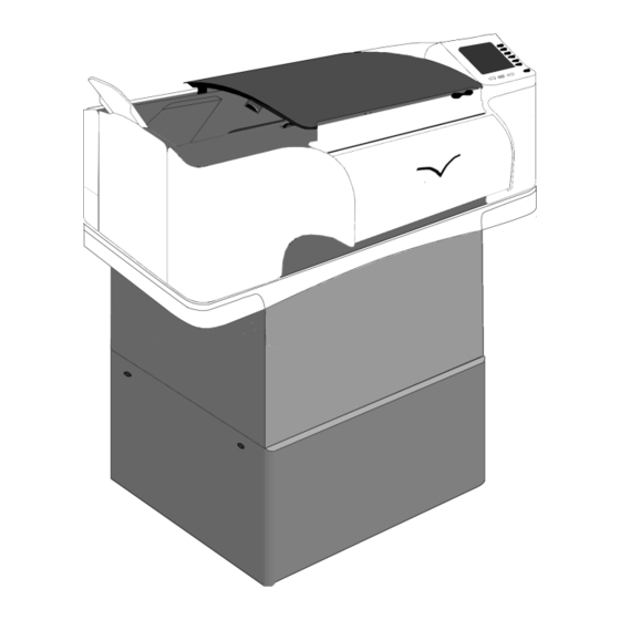
INSERTER IN-3 (SI-92)
OPERATOR MANUAL
1.
GENERAL
The SI-92 is a modular mailing system. For each stage within
the mailing process, such as feeding, folding, collating of
documents and inserting and sorting of filled envelopes a
module is available. In this way SI-92 adapts to the
customers' needs.
The whole system is operated and programmed via the
central operator panel of the base module, the inserter
(IN-3).
SI-92
Fig. 1
1/40
Advertisement
Table of Contents

Related Manuals for Neopost INSERTER IN-3 SI-92


Summary of Contents for Neopost INSERTER IN-3 SI-92
- Page 1 INSERTER IN-3 (SI-92) OPERATOR MANUAL GENERAL The SI-92 is a modular mailing system. For each stage within the mailing process, such as feeding, folding, collating of documents and inserting and sorting of filled envelopes a module is available. In this way SI-92 adapts to the customers' needs.
-
Page 2: Table Of Contents
CONTENTS Before using this system thoroughly read the operating Section Page Section Page instructions. In the European Union an operator manual FAULT FINDING GENERAL printed in the national language(s) is supplied with the General system. If it is not, contact your authorized distributor. HOW TO USE THE OPERATOR MANUALS 7.1.1 The error screen ACCESSORIES... -
Page 3: How To Use The Operator Manuals
bottle envelop slide set brushes (3 pcs.) dust brush mains supply cable press bracket Fig. 2 HOW TO USE THE OPERATOR MANUALS Use the SI-92 manual as the main guide. In the text of this ACCESSORIES manual we will refer to the other operator manuals if This SI-92 manual, existing of two parts, describes the The IN-3 is delivered with the accessories shown in Fig. -
Page 4: Understanding The Machine
envelop hopper insert position user interface sealing area exit Fig. 3 UNDERSTANDING THE MACHINE User interface The service engineer has access to all menus. The system can be started, stopped or cleared by pressing The user interface of the inserter exists of two menus; the Function the concerned key located below the display of the inserter, "main menu"... -
Page 5: Operating Controls
Fig. 4 Fig. 5 Fig. 6 Operating controls I : Envelop hopper Power inlet J : Release handle hopper A : Top cover See Fig. 6. The power inlet B is located at the rear side of the K : Release handle sealing table rollers B : Loc machine. -
Page 6: Display Keys
job number job name job counter preset counter counter Fig. 7 Fig. 8 Display keys OPERATING THE SYSTEM If the system is switched off after, for example, a paper stoppage, the brushes will not rest on the watertray. This Key 1 through 6 Preparations inserter module causes the brushes to dry if usage is interrupted for a longer See Fig. -
Page 7: Switching On
Fig. 9 Fig. 10 Fig. 11 Switching on Entering the personal pin code The main menu Switch on the inserter using the power switch A, see Fig. 9. In Fig. 10 the pin code screen is shown. The main menu is shown in Fig. 11. The "main menu"... -
Page 8: Job Info Screen Overview
Fig. 12 Fig. 13 Fig. 14 5.4.1 Job info screen overview When key 3 is pressed in the “job data” menu the upstream When key 6 is pressed in the upstream (transport) module (transport) module screen is displayed (see Fig. 13). The screen, the screen in Fig. - Page 9 Fig. 15 When key 4 is pressed in the “job data” menu the downstream (sorting) module screen is displayed (see Fig. 15). The screen shows the following functions: • select a higher job number (key 1). • select a lower job number (key 2). •...
-
Page 10: Schematic View
5.4.2 Schematic view 10/40 SI-92... -
Page 11: Selecting A Job
Fig. 16 Fig. 17 5.4.3 Selecting a job 5.4.4 Test run menu In case an FO-3 is used, a screen as shown in fig. 18 will be displayed. The envelope position keys 4 and 5 of figure 17 After pressing key 2 in the "main menu", the display shows After pressing key 3 in the "main menu"... - Page 12 (5x) Fig. 18 Fig. 19 Feed one envelope Insert one document Envelope stop position adjustment With this function the proper feed of envelopes can be The flap folding line must be positioned under the green With this function the proper functioning of the whole tested.
- Page 13 Fig. 20 Envelope fingers adjustment Fine tuning the folder settings The following functions are available: • test for a folded document 1x (key 1). It makes sense to In SI 92, if and when the electronic folder FO-3 is used, the When the envelope stop position is correct the insert fingers do this in the same menu screen.
-
Page 14: Counters Menu
Fig. 21 Fig. 22 5.4.5 Counters menu Increase and decrease preset counter 5.4.6 Settings menu By pressing key 4 or key 5 the preset counter will be After pressing key 4 in the "main menu", the display shows After pressing key 5 in the “main menu”, the screen as the "change counters"... -
Page 15: Entry To Job Menu
Fig. 23 Thickness detection Reset thickness detection Entry to job menu The IN-3 is equipped with a document thickness detector. By pressing key 5 the thickness detection will be reset. When key 6 in the “main menu” is pressed the display The thickness detector controls the thickness of the shows the screen in Fig. -
Page 16: Operator Menu Structure
Operator menu structure Select a job number for job Job data, page 8 data, see page 8 Select (upstream) VersaFeeder 1, 2 Select a job or transport module data Select (downstream) sorter module data Confirm selected job and go to main menu Feed one envelope from hopper A, page 12 Feed one envelope from hopper B Insert one document... -
Page 17: Envelope Hopper Adjustment
Fig. 24 Fig. 25 Envelope hopper adjustment 5.7.1 Side guides adjustment hopper A 5.7.2 Envelope separation hopper A The IN-3 can be equipped with a second hopper, the EF-3 Take a stack of about 20 envelopes. Fan the envelopes a bit Adjust the envelope separation by turning thumbwheel D see section 10.2 page 32. -
Page 18: Side Guides Hopper B
Fig. 26 5.7.3 Side guides hopper B 5.7.4 Envelope separation hopper B Take a stack of about 20 envelopes. Fan the envelopes a bit Adjust the envelope separation by turning knob B (Fig. 26) and place the envelopes in the system with the flap to the counter clockwise until two envelopes, one on top of the bottom side and trailing. -
Page 19: Performing A Job
PERFORMING A JOB Setting up the system Switch on the inserter IN-3 and, if part of the system, the AS-1A and PS-3 etc. Refer to the operator manuals of the used modules. Inserter IN-3 Action Refer to.. • Check the waterlevel, refill if necessary Refer to section 5.1 Preparations inserter module on page 6 •... - Page 20 Transport unit TR-7A, TR-1B Action Refer to.. Refer to the operator manuals of these modules if required. • If necessary adjust the module TR-7A. Refer to the chapter “Adjustments” and follow the instructions. Note 1: With SI-92 selection of a mode at the TR-7A is not applicable. Note 2: Information about where to put the address carrying documents and the enclosures can be found in the job info menu of the inserter.
- Page 21 AS-1A Action Refer to.. Refer to the operator manuals of these module if required. • If necessary adjust the module AS-1A. Refer to the chapter “Adjustments” and follow the instructions. 3d Party device Action Refer to.. Refer to the operator manuals of these modules if required. SI-92 21/40...
-
Page 22: Running A Job
Fig. 27 Running a job If documents from a previous job are detected on the Stop transport track (TR-7A), these are transported to the Press the stop key to stop the system. Start collating area of the TR-7A. The system then stops and indicates that these documents have to be removed. -
Page 23: Changing Settings Of A Module
Changing settings of a module Below the possible changes in settings are listed: Additional functions • the VersaFeeder modules 1 and 2 can be switched on or The settings of feed modules including the AS-1A are stored SI-92 provides additional operating functions. These are off via job settings. -
Page 24: Fault Finding
Fig. 28 Options FAULT FINDING 7.1.1 The error screen See chapter 10. The error screen (an example is shown in Fig. 28) provides General the following information: The IN-3 detects the following error types: • the error location, indicated by an arrow in the machine •... -
Page 25: The Information Screen
Fig. 29 Fig. 30 7.1.2 The information screen Configuration message If an FO-2A is replaced by an FO-3, the following default settings for the FO-3 will be used: The following message can occur if a job is selected in the By pressing key 1 in the error screen, an additional •... -
Page 26: The Call Screen
Fig. 31 Fig. 32 Fig. 33 7.1.4 The call screen 7.2.1 Removing documents 7.2.2 Stoppage in the document end feed When a technical error occurs the error screen will not When an error occurs in the document feed the error screen Remove documents in the following way: display the machine symbol. -
Page 27: Removing Documents From The Hopper
Fig. 34 7.2.4 Removing documents from the hopper 7.2.5 Removing envelopes from the insert or sealing 7.2.6 Stoppage on the insert table or sealing table table When an error occurs in the hopper the error screen shows Remove envelopes in the following way: the following symbol: When an error occurs in the inner part of the machine, the •... -
Page 28: Stoppage In The Envelope Track
7.2.7 Stoppage in the envelope track Remove envelopes in the following way: • lift the loc by pulling the release handle A of the loc (see Fig. 32). • lift the sealing table by pulling the locking handle B of the sealing table. -
Page 29: Error Codes
ERROR CODES General The central display of the inserter will display all system-wide errors that occur. When an error occurs, read the information on the screen, press the info key for more information. Follow the instructions. Generally an error number will be given. This number can be used for reference. see also.. -
Page 30: Additions To The Error Lists Of Other Modules
suggested solution see also..information Error code error description Configuration does not match. Switch the inserter off and restore the A module of the system has been removed.The con- configuration. figuration is not corresponding with the selected job. System can not be set. Select job again. -
Page 31: Maintenance
Fig. 35 Fig. 36 Fig. 37 MAINTENANCE General cleaning Cleaning the sealing roller The machine must be kept in proper condition by regularly The sealing roller A (Fig. 36) must be cleaned regularly with General removing dust, paper remains, etc. Clean the sealing table a slightly wetted cloth. -
Page 32: 10. Options
Fig. 38 Fig. 39 10. OPTIONS Transport unit TR-7A These are the possibilities with twin cycle: • all documents from stations 2, 3 and/or 4 have the same See TR-7A operator manual section 4.6. The TR-7A can be 10.1 General format and are all folded (no twin cycle). - Page 33 Fig. 40 When twin cycle is active the automatic deflector inside fold Feed unit FE-7, FE-9, ST-1 Feed unit FE-8 unit option is not available (See TR-7A operator manual Refer to FE-7/FE-9 (see Fig. 40) and operator manual OMR reading code chapter 8).
- Page 34 • control the moistening system of the inserter. will feed and read the enclosure with OMR code. standard built in Neopost code. Besides that, more than one • select the exit of the sorter. This matching of two document streams means that both reading code can be programmed.
-
Page 35: Si 92 Options
With this option active, the other feed units (stations 1 and Mix ’N Go ® standard built in Neopost code. Besides that, more than one 2) on the transport unit will feed an enclosure depending on the number of pages collated by the AS-1A. If the number of reading code can be programmed. - Page 36 The throats of both envelopes should have an equal shape. Type of enclosure (selective feed mark) Number of pages in a set (AS-1A only) Minimum requirements for Mix ’N Go ® The reading code of both the AS-1A and the FE-8 can Document sets that contain a number of sheets up to the - IN-3 equipped with EF-3.
- Page 37 Optionally this function can be combined with split set. Then If the system encounters a combination of selection criteria, it Error 60 document sets that contain a number of sheets up to twice will react as follows: the 'big' envelope will be selected if at Error 60 means "Split set too big"...
-
Page 38: 11. Specifications
11. SPECIFICATIONS This operator manual refers to machines as from serial number 02 BL-5191, IN-3. Refer to the operator manuals of the modules part of the configuration for specifications. Machine specifications Paper insert specifications Model Paper qualities : IN-3 (inserter head of SI-92) : according to existing feeding equipment (FE-7 and FE-1M) ≤... - Page 39 Maximum insert specifications are based on single sheets. When multiples are handled, more room inside the envelope is needed MACHINERY depending on application. (Directive 98/37/EEC, Annex II, sub A) Manufacturer: Neopost Technologies B.V. Address: De Tijen 3, 9201 BX Drachten The Netherlands...
- Page 40 40/40 SI-92...
Need help?
Do you have a question about the INSERTER IN-3 SI-92 and is the answer not in the manual?
Questions and answers