Neopost IS-5000 Installation Manual
With imeter postage meter
Hide thumbs
Also See for IS-5000:
- User manual (319 pages) ,
- Operator's manual (298 pages) ,
- Ppi installation (4 pages)

Related Manuals for Neopost IS-5000


Summary of Contents for Neopost IS-5000
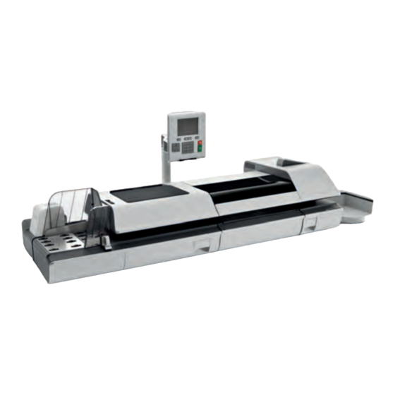
- Page 1 Installation Guide Mailing Systems with iMeter Postage Meter IS-5000 IS-6000 4148787C/D - 01/02/2015...
-
Page 2: Safety Requirements
Safety Requirements Please read this section carefully before connecting or using your equipment. Power Connection Before powering up your Mailing System, please check to ensure the system meets your local AC voltage requirements (110V). In addition to checking the power requirements, we also recommend that you: •... - Page 3 Compliance Energy Star® Compliance Office equipment is generally powered on 24 hours a day, so power management features are important for saving energy and reducing air pollution. Your Mailing System is an Energy Star® qualified Mailing System that automatically goes into a low-power 'Sleep' mode after a period of inactivity.
-
Page 4: How To Switch Between 'Sleep' And 'Wake' Modes
System Sleep Mode Your Mailing System is Energy Star® qualified and automatically goes into a low-power 'Sleep' mode after a period of inactivity. A very low-power 'Sleep' mode, called 'Soft-off' is also available. • The Mailing System will automatically switch to 'Sleep' mode after 5 minutes of non-activity. -
Page 5: General Specifications
General Specifications Base • Dimensions (Width x Length x Height): 25.19" x 10.74" x 13.42" • Weight : 45.20 lb • Power supply : 120 V (+/- 10 %) 3 prong • Frequency : 60 Hz • Maximum Input Power : 294W •... - Page 6 System Connections Base + Feeder Power...
- Page 7 Base + Feeder + Dynamic Weighing Module Power...
- Page 8 Base + Stacker Power...
-
Page 9: System Connectors
System Connectors Base connectors On the left-hand side The ON/OFF switch is located at the rear of the right ON/OFF switch hand side of the Mailing System base. Power connector To wall socket Power connector To Conveyor Stacker RJ 45 For future use USB ports To any USB device*... - Page 10 On the right-hand side USB ports To any USB devices* RS232 (COM1/2) Not applicable To Feeder or Dynamic Weighing Module DVI Connector To display Power connector To Feeder or Dynamic Weighing Module USB devices : Keyboard, Printer, Modem, LAN adaptor, Bar Code Reader… All USB devices have to be plugged with the system powered OFF.
- Page 11 Feeder connectors Power connector To Base or Dynamic Weighing Module To Feeder or Dynamic Weighing Module RJ45 For future use Dynamic Weighing Module connectors To Base To Feeder Power connector To Base...
- Page 12 Power connector To Base Conveyor Stacker connectors Power connector To Base...
Need help?
Do you have a question about the IS-5000 and is the answer not in the manual?
Questions and answers