Table of Contents

Related Manuals for Sony DFS-900M


Summary of Contents for Sony DFS-900M
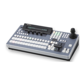
- Page 1 4-192-719-15 (1) Multi Format Switcher Operating Instructions Software Version 2.1 Before operating the unit, please read this manual thoroughly and retain it for future reference. DFS-900M Printed in Japan © 2010 Sony Corporation 4192719150...
- Page 2 The model and serial numbers are located on the bottom. Record these numbers in the spaces provided below. Refer to these numbers whenever you call upon your Sony This symbol is intended to alert the user to dealer regarding this product.
- Page 3 • Leave a space around the unit for ventilation. • Leave more than 10 cm of space in the rear of the unit to Le fabricant de ce produit est Sony Corporation, 1-7-1 secure the operation area. Konan, Minato-ku, Tokyo, Japon.
- Page 4 Für die folgende elektromagnetische Umgebung: E4 (kontrollierter EMV-Bereich, z.B. Fernsehstudio). Ne pas utiliser cet appareil dans une zone résidentielle. Der Hersteller dieses Produkts ist Sony Corporation, 1-7-1 Pour les clients en Europe, Australie et Nouvelle- Konan, Minato-ku, Tokyo, Japan. Zélande Der autorisierte Repräsentant für EMV und...
-
Page 5: Table Of Contents
8 M/E Transition Block ..............25 9 DME/SETUP Block ..............25 0 Joystick Block ................26 qa Numeric Keypad................26 qs Display Panel/Menu Control Block..........26 BKDF-902 Rear Panel................. 26 DFS-900M Processor Unit............. 28 Front Panel ..................28 Rear Panel.................... 28 Table of Contents... - Page 6 Options ................... 31 BKDF-910 4 SDI Input Board ............31 BKDF-911 2 SD Video Input Board........... 31 BKDF-912 2 DVI Input Board............31 BKDF-960 4 SDI Output Board............31 BKDF-961 2 SD Video Output Board ..........31 BKDF-962 2 DVI Output Board ............32 BKDF-990 Power Supply Unit ............
- Page 7 Chapter 4 Basic Operations Selecting Backgrounds ...............108 Switching Backgrounds.............. 109 Cutting to a New Background ............109 Cutting by using GPI output.............. 111 Using Transitions to Switch to the Next Video (Mix and Wipe) ..111 Switching with Mix Transitions ............113 Switching with Wipe and DME Wipe Transitions......
- Page 8 Adding Lighting Effects ..............146 Registering User Patterns ..............147 Applying Masks to Keys ............. 147 Adding Edges to Keys..............148 Masking Downstream Keys with Box Masks ......150 Chapter 6 Registering Operations and Settings Event Operations .................151 Registering Events................151 Recalling Events................
- Page 9 Troubleshooting ................205 Problems during Startup ..............205 Problems on Video Input and Output..........205 Problems on Functions ..............206 Specifications ................207 DFS-900M Processor Unit ..............207 BKDF-901 1M/E Control Panel............207 BKDF-902 1.5M/E Control Panel............. 208 Table of Contents...
- Page 10 Optional Products ................208 Pin Assignments ................211 Example Connection of GPI Input ............ 214 Example Connection of Tally/GPI Output ........214 External Dimensions ..............215 Glossary ..................218 Index ..................... 219 Table of Contents...
-
Page 11: Chapter 1 Overview
Overview Chapter Features of This System The DFS-900M Multi Format Video Switcher is a compact switcher incorporating Digital Multi Effects (DME) functionality, and supporting both SD and HD systems. Multi-format support The system supports 480i/59.94 and 576i/50 formats for an SD system, and 1080i/59.94, 1080i/50, 720p/59.94, and 720p/50 formats for an HD system. -
Page 12: Functions Newly Supported In Version 2.0
You can also connect a commercially available touch panel monitor. This allows you to select menu items simply by touching the panel, making it much more convenient to change system settings and adjust setting values. Compact and easy-to-use control panels Two types of highly compact and easy-to-use control panels are available, each one designed to meet the requirements of space-limited applications. -
Page 13: Chapter 2 Names And Functions Of Parts
Names and Functions of Chapter Parts BKDF-901 1M/E Control Panel BKDF-901 Operating Blocks This section explains the functions of control panel parts For information about the rear panel of the control panel, by dividing them into nine blocks, as shown below. see “BKDF-901 Rear Panel”... -
Page 14: External Connections And Power Block
1 External Connections and Power 2 KEYER Block Block This block allows you to select a key type, to add a mask or edge (shadow) to a key, and to enable or disable DME. This block provides a connector for USB flash drives, The operation target key must be selected in advance (see buttons to turn control by editors and GPI on and off, and page 15). -
Page 15: Key Delegation Block
b PRESET selection button row Second press: With DME still enabled, use a key-processed signal as the key. These buttons select the video that will be the on-air background after a transition. Third press: The button goes out, and DME is disabled The signals that are assigned to the buttons in this row are again. -
Page 16: Joystick Block
When you press this button, lighting it, and then execute a AUTO TRANS (auto transition) button: Executes a transition with the fader lever, the video of the transition is transition using a downstream key. output to the preview screen. f FTB (fade to black) button Executes a transition in which the video changes to black. -
Page 17: Numeric Keypad
a DEFAULT button Returns the setting values of parameters assigned to the Y coordinate + joystick to the default values. Z coordinate – Z coordinate + b AUTO CK (auto chroma key) button Initiates and confirms the creation of an auto chroma key. Pressing this button once selects auto chroma key mode, in X coordinate –... -
Page 18: Dme/Setup Block
Button display Function 4 SHIFT button Switches to the next menu. 3 USER/STILL button EVENT Switches to event mode. 1 DME setting buttons Switches to sequence mode. Switches to the previous sub menu. Switches to the next sub menu. Buttons used when the EVENT button is lit (event mode) 2 Setup buttons Button display... -
Page 19: Display Panel/Menu Control Block
c USER/STILL button display area for four parameters. Useful supporting When pressed with the SHIFT button unlit, displays the information for menu operations may appear in the upper menu used for management of user specified wipe patterns right. and DME wipe patterns. When pressed with the SHIFT b F1 to F4 knobs button lit, displays the menu for still image storage operations, such as download, capture, and export. - Page 20 Use the supplied control cable to connect to the PANEL connector of the processor unit. Note This connector is for connection to the DFS-900M processor unit only. It cannot be connected to the processor unit of any other system. CAUTION •...
-
Page 21: Bkdf-902 1.5M/E Control Panel
BKDF-902 1.5M/E Control Panel BKDF-902 Operating Blocks This section explains the functions of control panel parts For information about the rear panel of the control panel, by dividing them into twelve blocks, as shown below. see “BKDF-902 Rear Panel” (page 26). For details, see the pages indicated within parentheses. -
Page 22: External Connections And Power Block
1 External Connections and Power 2 KEYER Block Block See descriptions for the BKDF-901 in “2 KEYER Block” (page 14). See descriptions for the BKDF-901 in “1 External Connections and Power Block” (page 14). 3 Key/AUX (Auxiliary) Bus Control Block 1Key delegation buttons 2AUX delegation buttons 3KEY/AUX bus selection buttons... -
Page 23: 4 M/E Cross-Point Bus Block
The SHIFT buttons have two operating modes: one in For details, see “Selecting the operating mode of the which the buttons function as shift buttons only while held SHIFT buttons” (page 105). down, and one in which the shift function is alternately enabled and disabled each time the buttons are pressed. -
Page 24: Program/Preset Transition Block
1PROGRAM bus selection button row 2PRESET bus selection button row 3M/E buttons a PROGRAM bus selection button row a Transition type selection buttons MIX button: Press this button, lighting it, to select a mix See descriptions for the BKDF-901 in “PROGRAM transition. -
Page 25: 8 M/E Transition Block
b Transition type selection buttons 1 FTB (fade to black) MIX button: Press this button, lighting it, to select a mix button transition. The Rate menu appears in the display panel, allowing you to specify the transition rate. WIPE (FAM (full additive mix)) button: Press this button, lighting it, to select a wipe transition. -
Page 26: Joystick Block
c Setup buttons 1 DME setting buttons See descriptions of “Setup buttons” (page 18) for the 2 USER button BKDF-901. d STILL button Displays the menu for still image storage operations, such as download, capture, and export. 0 Joystick Block 4 STILL button See descriptions for the BKDF-901 in “6 Joystick Block”... - Page 27 7 POWER switches A and B 6 -AC IN connectors A and B 5 Ground terminal 4 DEVICE connector 3 MAINTENANCE connector 2 PROCESSOR connector 1 EXT DISPLAY connector On how to use each connectors and switches, see descriptions in “BKDF-901 Rear Panel” (page 19). BKDF-902 1.5M/E Control Panel...
-
Page 28: Dfs-900M Processor Unit
DFS-900M Processor Unit POWER switch and indicator Front Panel Powers the processor unit on and off. Press the = of the switch to power the unit on. The indicator lights in green when the unit is powered on. POWER switch and indicator You can install the optional BKDF-990 Power Supply Unit for use as a backup power supply. - Page 29 REF IN connector, this connector outputs the internal sync connector. If you will not be using loop-through output, signal used by the switcher as the reference signal. terminate the connector with a 75 Ω terminator. DFS-900M Processor Unit...
-
Page 30: Power Connectors
Use the supplied control cable to connect to the PROCESSOR connector of the control panel. Note This connector is for connection to the DFS-900M control 3 Ground terminal panel only. It cannot be connected to the control panel of any other system. -
Page 31: Options
BKDF-912 2 DVI Input Board Options DVI IN (DVI input) 1 and 2 connectors BKDF-910 4 SDI Input Board SDI IN 1 to 4 connectors DVI IN (DVI input) 1 and 2 connectors (DVI-I type) Connect a computer which is equipped with DVI output connectors. -
Page 32: Bkdf-962 2 Dvi Output Board
• BKDF-950 Multi Viewer Board Connector Connector Output signals number name Composite Component COMP/Y Composite Luminance signal signal (Y) Not used Color difference signal (B-Y) Not used Color difference signal (R-Y) COMP Composite signal For signal settings, see “Specifying the signal type of analog output signals”... -
Page 33: Chapter 3 Preparations
Preparations Chapter Connecting Peripheral Devices This section provides examples of how to connect peripheral devices. After connecting a peripheral device to the switcher, use the menu system to make basic settings. Notes • When you connect a device that does not allow input of external sync signals, you can achieve synchronization by enabling the frame synchronizer of the input connector to which you have connected that device. - Page 34 To reference To reference Camera with To reference Camera with signal input signal input HD-SDI signal input HD-SDI output output (PMW-350, (PMW-EX3, etc.) etc.) Key signal generator or other device with HD-SDI output To reference To reference Camera with To reference Camera with signal input signal input...
-
Page 35: Connection Example 2: System With Editor Connected
Connection Example 2: System with Editor Connected The figure below shows an example of a video editing system with a recorder, multiple players, signal output devices, and an editor to control the other devices. Connect the HD-SDI output of the output devices to the SDI IN connectors of the switcher. - Page 36 To reference signal input To reference signal input To reference signal input To REMOTE To REMOTE To REMOTE Key generator or other device Editor with HD-SDI output Player or other Player or other device with device with HD-SDI output HD-SDI output To EDITOR To SDI To SDI...
-
Page 37: Connection Example 3: Connection To A Device Equipped With A Dvi (Dvi-I) Connector
Connection Example 3: Connection to a Device Equipped with a DVI (DVI-I) Connector You can use the optional BKDF-912 2 DVI Input Board or the optional BKDF-962 2 DVI Output Board to connect the switcher to a computer or other device equipped with a DVI-I connector. - Page 38 Computer Computer Computer To HD15 input connector To DVI To HDMI To DVI connector connector connector DVI-I h HD15 Monitor or other conversion adaptor device with HD15 DVI-I h HDMI input connector conversion cable To DVI1 To DVI2 To DVI1 To DVI1 To DVI1 To DVI2...
-
Page 39: Installing Optional Expansion Boards
Installing Optional Expansion Boards This section explains how to install I/O expansion boards, function expansion boards, and the optional power supply unit. The following expansion options are available. For more information about the various options, see page 31. Type and function of expansion options Model number Input expansion 4 SDI Input Board... - Page 40 Input expansion board Output expansion board installation location installation location A number is assigned to each of the channels on installed I/O expansion boards (IN09 to IN24 on input expansion boards, and AUX03 to AUX10 on output expansion boards). The following table lists the installation locations of the various boards and the numbers assigned to their channels after installation.
- Page 41 Output expansion board channel numbers Installation position on expansion board installation tray Lower tray Upper tray Left Center Right Left Center Right Whether board can be installed Output BKDF-960 – – AUX03 – – AUX07 number 4 SDI Output display after Board AUX06 AUX10...
- Page 42 Use the following procedure to remove the panels on the expansion board installation tray. 1Remove the two screws (+M3) securing the ventilation adjustment panel, and remove the ventilation adjustment panel. 2Remove the two screws (+M2.6) securing the blank panel where you want to install an I/O expansion board, and remove the blank panel.
- Page 43 Use the following procedure to affix the heat transfer sheet (supplied with each I/O expansion board) to the expansion board installation tray. 1Remove the adhesive surface cover sheet from one side only of the heat transfer sheet. 2Hold the bottom side of the heat transfer sheet (the side from which you removed the adhesive cover sheet) down and affix it to the expansion board installation tray, aligning it with the positioning guide frame on the expansion board installation tray.
- Page 44 3Remove the adhesive surface cover sheet from the top side of the heat transfer sheet. (For input expansion boards) (For output expansion boards) Push the connectors of the expansion board through the inner side of the connector name plate frame, place the expansion board on the expansion board installation tray, and secure the board with the supplied four +M3 screws.
- Page 45 Expansion board Screws Tightening torque BKDF-910 +M2.6 × 4 0.49N·m BKDF-911 BKDF-960 BKDF-961 BKDF-912 Hexagon head bolt 0.5N·m BKDF-962 (5mm in width across flats) × 4 Note For the BKDF-912 and BKDF-962, use a nut driver to tighten the hexagon head bolt.
-
Page 46: Installing Function Expansion Boards
Using the four screws removed in step 1, attach the board tray stabilizers. To remove I/O expansion boards Carry out the installation procedure in reverse. Installing Function Expansion Boards About installation locations Pull the standard I/O module out from the rear panel of the processor unit, and install the function expansion boards on the standard I/O module. - Page 47 Standard I/O module MV1 socket DME1 socket MV2 socket DME2 socket To install function expansion boards Use the following procedure to install function expansion boards. Remove the four screws (+B 3×6) securing the board tray stabilizers, and remove the stabilizers. As shown in the figure below, push the levers on each end of the standard I/ O module to open them, and then pull the standard I/O module out.
- Page 48 If you are installing the BKDF-940, proceed as follows to affix the heat transfer sheet supplied with the BKDF-940 to the function expansion board. 1Remove the adhesive surface cover sheet from one side only of the heat transfer sheet. 2Hold the bottom side of the heat transfer sheet (the side from which you removed the adhesive cover sheet) down and affix it to the standard I/ O module, aligning it with the positioning guide frame on the standard I/O module.
- Page 49 3Remove the adhesive surface cover sheet from the top side of the heat transfer sheet. Align the connectors of the function expansion board with the sockets on the signal processing board of the standard I/O module, grasp the board near the connector, and push the board down until the connector is coupled into the socket.
- Page 50 Insert the standard I/O board into its original slot, and align the notches of the levers on both sides of the board to the left and right sides of the slot mouth. As shown in the figure below, lock the standard I/O module by pulling the levers toward the inside.
-
Page 51: Installing The Bkdf-990 Power Supply Unit
Using the four screws removed in step 1, attach the board tray stabilizers. To remove function expansion boards Carry out the installation procedure in reverse. Installing the BKDF-990 Power Supply Unit To install the BKDF-990 Remove the front panel of the processor unit, remove the internal blank panel, and then install the BKDF-990. - Page 52 Remove the two screws (+B 4×8) securing the blank panel inside the processor unit, and remove the blank panel. Insert the BKDF-990 into the installation slot inside the processor unit, and push it all the way in. Using the two screws removed in step 2, secure the BKDF-990 to the processor unit.
- Page 53 Using the two screws removed in step 1, attach and secure the front panel. To remove the BKDF-990 Power off the BKDF-990, and then carry out the installation procedure in reverse. Installing Optional Expansion Boards...
-
Page 54: Connecting Up The Switcher
Connecting Up the Switcher This section explains how to connect up the switcher system. Changing the Internal Switch Setting in the Processor Unit (When Using the BKDF-902) When using the BKDF-902, change the setting of a DIP switch on the external device interface connectors board in the processor unit. - Page 55 Set pin 2 of the DIP switch under the flat cable to the “ON” position. Note Do not change settings of the other pins. Insert the external device interface connectors board into its original slot, and align the notches of the levers on both sides of the board to the left and right sides of the slot mouth.
- Page 56 As shown in the figure below, lock the board by pulling the levers toward the inside. The board is pushed all the way into the slot and locked in place. Using the four screws removed in step 1, attach the board tray stabilizers. Connecting Up the Switcher...
-
Page 57: Connecting The Processor Unit And The Control Panel
Connecting the Processor Unit and the Control Panel Using the control cable supplied with the processor unit, connect the PANEL connector of the processor unit and the PROCESSOR connector of the control panel. After connecting the control cable, use two AC power cords (not supplied) to connect the processor unit and the control panel to an AC power source. -
Page 58: Powering The System On
When using the BKDF-901 BKDF-901 control panel To - AC IN To PROCESSOR AC power cord (not supplied) To AC power Control cable (supplied) To PANEL Processor unit To - AC IN AC power cord (not supplied) To AC power When using the BKDF-902 BKDF-902 control panel To - AC IN... - Page 59 BKDF-902 BKDF-901 Turn on the POWER switch on the processor unit by pressing the @ of the switch. The processor unit is powered on, and the POWER indicator lights in green. Turn on the POWER switch (when using the BKDF-901) or the POWER switches A and B (when using the BKDF-902) on the rear panel of the control panel.
- Page 60 Display panel The following messages appear in the display panel during boot mode. Now Initializing…Please Wait…: Initializing Now initial communication started.: Establishing communication between the control panel and the processor unit Pull the fader lever once from the top of its range all the way to the bottom. Power on the peripheral devices.
- Page 61 BKDF-902 BKDF-901 Press the SHUTDOWN button. The following message appears in the display panel. Press the F2 knob. Shutdown processing (storage of the various settings) begins. When storage of the setting ends, the following message appears in the display panel. Connecting Up the Switcher...
- Page 62 Note Do not turn off the power switches during shutdown processing. If you turn off the power before the shutdown finishes, the switcher may become unable to boot normally. Turn off the POWER switch (when using the BKDF-901) or the POWER switches A and B (when using the BKDF-902) on the rear panel of the control panel.
-
Page 63: Menu Operations
Menu Operations Menus shown in the display panel allow you to make settings for the entire system, select effects, and so on. This section explains the types of menus, the configuration of the menu system, and basic menu operations. Basic Menu Configuration The menus of this switcher are divided into the following categories, depending on the type of operation and the setting target. -
Page 64: Operating In Menus
Sub menu name display Display panel Operating in Menus Use the F1 to F4 adjustment knobs to change and save settings. Setting names and values appear in the display panel above the corresponding adjustment knobs. F1 knob operation area F2 knob operation area F3 knob operation area F4 knob operation area Setting adjustment knobs... - Page 65 in the monitor. This can be an aid to smooth operations because it allows you to take in the entire menu system and several menu levels at a glance. Instead of the mouse and monitor, you can also connect a commercially available touch panel monitor.
- Page 66 When selecting a PC monitor or touch panel monitor to connect to this switcher, select one with at least SVGA (800×600) resolution and the ability to adjust the resolution automatically. To calibrate a touch panel monitor If you have connected a touch panel monitor, you must calibrate it when you power the switcher on for the first time.
- Page 67 Press the center point of the calibration mark in the upper left corner of the screen. The mark disappears when you press it, and another mark appears in the bottom right corner of the screen. Press the center point of the calibration mark in the bottom right corner of the screen.
- Page 68 Press the mark on the screen. The control panel is powered off and then starts again automatically. The new settings are reflected when it starts again. Press the mark to return to the calibration screen of step 4. Note Calibrate the touch panel monitor again if you notice that a touch position is different from the display position.
- Page 69 c Status section Displays the number of DME channels in use, the transition rate, and other status information. d Parameter section Displays the current settings of the current sub menu. Basic operations in the GUI menu screens To select menu and sub menu items If you have connected a PC monitor and a USB mouse, move the cursor to the menu or sub menu item that you want to set, and then left click the mouse.
- Page 70 F1 knob F2 knob F3 knob F4 knob operation area operation area operation area operation area Note The names of menus and sub menus in the GUI menu screens differ from the names that appear in the display panel of the control panel. See page 176 for a list of menus and their names as they appear in GUI menu screens and the display panel.
-
Page 71: Basic Switcher Settings
Basic Switcher Settings This section explains how to make settings that must be made before you can operate the switcher, such as the video format, the selection of I/O channels, etc. Setting the Video Format Use the following procedure to set the format of the video signals handled by the switcher. - Page 72 525/59: SD signal (NTSC) 625/50: SD signal (PAL) 720/50: HD signal (720p/50 Hz) 720/59: HD signal (720p/59.94 Hz) 1080/50: HD signal (1080i/50 Hz) 1080/59: HD signal (1080i/59.94 Hz) Note Settings values are highlighted if they are different from the current setting value.
-
Page 73: Making Input And Output Reference Sync Signal Settings
7.5%: Set the black setup level to 7.5%. F3 knob (SD ASPECT) setting 4: 3: Video with aspect ratio of 4: 3 SQ: Squeeze video Note If you have connected a black burst signal to the REF IN connector of the switcher, and SET is set to 7.5%, then a 7.5% setup level is added to the black burst signals (both SD and HD) output from the REF OUT connector. -
Page 74: Making Settings Related To Input Signals
Make the reference sync signal settings. Rotate the F1 knob to specify an input sync signal, and rotate the F2 knob to specify an output sync signal. The correspondence between knobs and parameters is as follows. Knob Parameter Description Setting range Ref-I Input reference sync BB: Black burst signal... - Page 75 BKDF-901 BKDF-902 Insert a USB flash drive into the USB MEMORY connector. When using the BKDF-901: If the SHIFT button of the DME/SETUP block is not lit, press it to light it. When using the BKDF-902: Skip to step 3. Press the INPUT button.
- Page 76 Remove the USB flash drive from the USB MEMORY connector, and load the file into a computer. Use Notepad or another text editor to edit the display names (the strings after the equals signs). The following characters can be used in display names. The maximum number of characters per name is four.
- Page 77 When optional input expansion boards are installed, you can use the SHIFT buttons to assign up to 26 signals, including video input signals 1 to 24, four color matte signals, four still images, and a black signal. The following signals are assigned when the switcher is shipped from the factory.
- Page 78 BKDF-901 BKDF-902 When using the BKDF-901: If the SHIFT button of the DME/SETUP block is not lit, press it to light it. When using the BKDF-902: Skip to step 2. Press the INPUT button. A settings sub menu of the Input sub menu appears in the display panel. Press the h or H button in the numeric keypad until the Setting 1 sub menu appears.
- Page 79 A list of signal names, specified with the procedure described in “Changing signal display names” (page 74), appears in the menu screen. The selected signal is assigned to the selected button. Repeat steps 4 and 5 to assign signals to other buttons. Using the internal frame synchronizers Each of the switcher’s input connectors (including those on optional expansion boards) has an internal frame synchronizer.
- Page 80 When using the BKDF-901: Press the PRESET selection button that selects the input you want to set. If you want to set an input that has been assigned by using the SHIFT button (see page 76), press the SHIFT button before pressing the PRESET selection button.
- Page 81 • When you download a still image to the memory of an input (see page 118), the frame synchronizer mode of that input is set automatically to On. At the same time, the output signal is set automatically to Frm. Change the setting as required after downloading the still image.
- Page 82 BKDF-901 BKDF-902 When using the BKDF-901: If the SHIFT button of the DME/SETUP block is not lit, press it to light it. When using the BKDF-902: Skip to step 2. Press the INPUT button. A settings sub menu of the Input sub menu appears in the display panel. Press the h or H button in the numeric keypad until the Setting 2 sub menu appears.
- Page 83 Rotate the F3 knob to select the conversion mode. 4:3: Input with 4:3 aspect ratio (add black to left and right sides of picture) 4:3BGS: Input with 4:3 aspect ratio (Add still images to the left and right sides of picture. The two sides of a downloaded still image file (HDTV size) are added to the video input.) SQ: Input as squeeze video LB: Input as letterbox video...
- Page 84 A settings sub menu of the Input sub menu appears in the display panel. Press the h or H button in the numeric keypad until the Setting 2 sub menu appears. “Setting2” appears in the sub menu title display area. If it is already displayed there, you can skip this step.
- Page 85 Setting Name of Input signal BKDF-911 installation position of step 5 BKDF-911 and channel number connector Lower tray Upper tray Left Center Left Center Y/CB/CR COMP/Y Luminance IN09 IN13 IN17 IN21 (Y) signal Color difference (B-Y) signal Color difference (R-Y) signal COMP Composite IN10...
- Page 86 BKDF-901 BKDF-902 When using the BKDF-901: If the SHIFT button of the DME/SETUP block is not lit, press it to light it. When using the BKDF-902: Skip to step 2. Press the INPUT button. A settings sub menu of the Input sub menu appears in the display panel. Press the h or H button in the numeric keypad until the DVI sub menu appears.
- Page 87 Rotate the F2 knob to select the picture size and aspect ratio conversion modes. Normal: Do not convert either the picture size or aspect ratio. Zoom: Expand the screen size to match the horizontal width of a 16:9 aspect ratio picture (vertical and horizontal zoom ratios are the same). Full: Modify the picture size to match a 16:9 aspect ratio picture, so that all areas of the picture are displayed (the vertical and horizontal modification ratios are different).
- Page 88 When using the BKDF-901: If the SHIFT button of the DME/SETUP block is not lit, press it to light it. When using the BKDF-902: Skip to step 2. Press the INPUT button. A settings sub menu of the Input sub menu appears in the display panel. Press the h or H button in the numeric keypad until the Input Process1 or Input Process2 sub menu appears, depending on what you want to adjust.
-
Page 89: Making Settings Related To Output Signals
Knob Parameter Description Setting range Adjust the hue 0.0 to 359.5 a) Valid only when the BKDF-911 2 SD Video Input Board is installed Making Settings Related to Output Signals Selecting output signals for AUX output Including the four standard video outputs (PGM1/2 and AUX1/2), you can use up to 12 video outputs by adding option boards. - Page 90 When using the BKDF-901: Rotate the F1 knob to select an output, from AUX1 to AUX10. When using the BKDF-902: Skip to step 3. Note AUX3 to AUX10 are available only when optional expansion boards are installed. For details, see page 39. Rotate the F2 knob to select the signal to assign.
- Page 91 Note To output ancillary data, disable the frame synchronizers (page 79). It will also be disabled to use a function which captures still images from input video signals (page 80). Making down-convert output settings The optional BKDF-960 and BKDF-961 output expansion boards feature internal down-converters.
- Page 92 When using the BKDF-901: Press the AUX button. When using the BKDF-902: Among the AUX03 to AUX10 buttons, press the button that selects the AUX output that you want to set. The Aux (AUX output assignment settings) sub menu appears in the display panel.
- Page 93 BKDF-901 BKDF-902 When using the BKDF-901: Press the AUX button. When using the BKDF-902: From among the buttons AUX03 to AUX10, press one to which analog output has been assigned. The Aux (AUX output assignment settings) sub menu appears in the display panel.
- Page 94 Setting of Name of Output signal BKDF-961 installation step 4 BKDF-961 position and channel connector number Lower tray Upper tray Left Left Compst COMP/Y Composite signal AUX03 AUX07 – – – – – – COMP Composite signal AUX04 AUX08 Y-CB/CR COMP/Y Y (luminance) signal AUX03...
- Page 95 BKDF-901 BKDF-902 When using the BKDF-901: Press the AUX button. When using the BKDF-902: From among the buttons AUX03 to AUX10, press one to which DVI output has been assigned. The Aux (AUX output assignment settings) sub menu appears Press the h or H button in the numeric keypad until the DVI (DVI output settings) sub menu appears.
- Page 96 Parameter Output signal Video format setting Yes: Can be selected No: Cannot be selected (the parameter does not appear) 525/59 or 720/50 or 1080/50 or 625/50 720/59 1080/59 WXGA WXGA signal (1280 x 768) SXGA SXGA signal (1280 x 1024) UXGA UXGA signal (1600 x 1200)
- Page 97 Preview video Program video Multi-view screen example (10 partitions) You can install up to two BKDF-950 boards, and set output patterns for each board in both the MV1 Window and MV2 Window sub menus. You also change the size and position of child window titles, and add frames to indicate that the signal assigned to a child window is program or preview output or a component element of program or preview output (the currently selected input, a key signal, and so on).
- Page 98 Press the h or H button in the numeric keypad until the MV1 Window or MV2 Window sub menu appears. As shown in the following table, the sub menu title in the display panel indicates the BKDF-950 board targeted by this procedure. If the title that you want is already displayed there, you can skip this step.
- Page 99 Notes • When optional input expansion boards have been installed, signal names corresponding to the installation positions appear for IN09 to IN24. For details, see page 39. • When the display names of input signals or internal signals have been changed (see page 74), the user-specified names appear.
- Page 100 Parameter Description Setting values LargeHeight Specifies the height of characters in 0 to 50 large child windows. SmallOffsetV Specifies the vertical display position in 0 to 25 small child windows. SmallOffsetH Specifies the horizontal display 0 to 25 position in small child windows. SmallWidth Specifies the display width in small 0 to 25...
- Page 101 To add frames to child windows You can add frames to child windows to indicate that the signal assigned to a child window is program or preview output or a component element of program or preview output (the currently selected input, a key signal, and so on). Tips •...
- Page 102 Name displayed in sub Description menu title display area MV1 Next Tally Among the multi-view child windows displayed by a BKDF-950 connected to MV1 socket, display a frame around windows that display the video to be sent to program output next, or component elements of that output.
- Page 103 Enabling the DSK preview function When downstream keys are off, you can display them in the preview window (DSK preview function). BKDF-901 BKDF-902 When using the BKDF-901: If the SHIFT button of the DME/SETUP block is not lit, press it to light it. When using the BKDF-902: Skip to step 2.
-
Page 104: Making Other Settings
Making Other Settings Specifying the timing of video switching You can specify whether to switch video signals on odd fields, even fields, or any field. BKDF-901 BKDF-902 When using the BKDF-901: If the SHIFT button of the DME/SETUP block is not lit, press it to light it. When using the BKDF-902: Skip to step 2. - Page 105 Note This setting is ignored when the video format setting is 720/50 or 720/59 (see page 71). Selecting the operating mode of the SHIFT buttons Use the following procedure to select the operating mode of the SHIFT buttons of the cross-point bus block. BKDF-901 BKDF-902 When using the BKDF-901: If the SHIFT button of the DME/SETUP...
-
Page 106: Setting The Date And Time
Setting the Date and Time Use the following procedure to set the date and time of the switcher’s internal clock. BKDF-901 BKDF-902 When using the BKDF-901: If the SHIFT button of the DME/SETUP block is not lit, press it to light it. When using the BKDF-902: Skip to step 2. - Page 107 Press the H button once to display the Time Adj. (set time) sub menu. “Time Adj.” appears in the sub menu title display area. Rotate the F2, F3, and F4 knobs to set the hour, minute, and second. The correspondence between knobs and parameters is as follows. Knob Parameter Description...
-
Page 108: Chapter 4 Basic Operations
Basic Operations Chapter Selecting Backgrounds PROGRAM selection buttons The output from the PGM1 and PGM2 connectors is called the “program output video”. You can check it on the program monitor and in the multi-view screen. BKDF-901 For more information about the multi-view screen, see M/E bus A selection buttons “Making multi-view output settings”... -
Page 109: Switching Backgrounds
Switching Backgrounds A replacement of one or more of the video elements that make up the current program output by another video PRESET selection buttons element is called a “transition”. BKDF-901 Video elements include the background and keys 1 to 4. A transition can involve changes in one element or simultaneous changes in a number of elements. - Page 110 Example: When PROGRAM selection button 1 and Preview video Program video PRESET selection button 4 are selected Before pressing the CUT button Lit in red Lit in green Multi-view screen example (10 partitions) After pressing the CUT button For details, see “Making multi-view output settings” Lit in red (page 96).
-
Page 111: Cutting By Using Gpi Output
The pressed button lights in green, and the selected Cue up the playback device. video appears in the preview screen. While holding down the WIPE transition type Press the CUT button. selection button, press the DME button. The program output and preview output video are CG Wipe is selected switched instantly. - Page 112 Buttons and controls used to execute transitions For information about how to set transition rates, see “Setting Transition Rates” (page 117). NORM/REV button Using the fader lever REVERSE button To execute a transition, move the fader lever in the direction of the lit transition indicator (a). The transition starts, and proceeds according to the rate at which you move the lever.
-
Page 113: Switching With Mix Transitions
Limiting the effective range of the fader When using the BKDF-902: If you press the FADER LIMIT button in the M/E transition block, rotate the lever F1 knob to set the limit (0.0 to 100%). If you press the You can limit the effective range of the fader lever (cause FADER LIMIT button in the PROGRAM/PRESET transitions to end before the fader lever reaches the top or transition block, rotate the F2 knob to set the limit (0.0... - Page 114 When using the BKDF-901 When using the BKDF-902 In the transition block, press the BKGD next transition selection button, lighting it. In the M/E transition block, press the BKGD next In the cross-point bus block, press a PROGRAM transition selection button, lighting it. selection button to select the video that appears before the transition.
-
Page 115: Switching With Wipe And Dme Wipe Transitions
Press the WIPE or DME transition type selection button, lighting it. The WIPE menu or the DME menu appears in the display panel. Each time you press the AUTO TRANS button or move the fader lever, a mix transition is executed WIPE menu between the two currently selected video signals. - Page 116 When using the BKDF-902 When the WIPE button of the PROGRAM/PRESET transition block is pressed, the P/P WIPE menu appears in the display panel. P/P WIPE menu P/P Wipe Pattern Pat=0 Wid=9.1 Soft=12.5 Src=W.Bd Note DME must be enabled to use DME wipe patterns. Pressing the DME button when DME is not enabled has no effect.
-
Page 117: Setting Transition Rates
Setting Transition Rates Using Color Mattes Transition rates specify the time required to complete a transition after an AUTO TRANS button is pressed. You Video input signals are not the only signals that you can can set the desired transition rate across the range 1 to 999 use in transitions. -
Page 118: Using Color Mattes In Background Transitions
When using the BKDF-901: If the SHIFT button in Using Internally Stored the DME/SETUP block is not lit, press it to light it. When using the BKDF-902: Skip to step 2. Still Images Press the MATTE button. The switcher is equipped with internal memory for the The Matte Color menu appears in the display panel. - Page 119 Store the images that you want to use on a USB flash Notes drive, and connect the USB flash drive to the USB • Still image files downloaded from USB flash drives are MEMORY connector. also stored in the non-volatile memory of the control panel.
-
Page 120: Using Stored Still Images In Background Transitions
When using the BKDF-902: With the video that you Note want to capture being output to program output, If you have changed the display names of input signals skip to step 2. and internal signals (see page 74), those names appear in the F1 knob operation area. -
Page 121: Writing Still Images To Usb Flash Drives
Note Knob Parameter Description Settings 32-bit files cannot be stored in memory locations other File format BMP, TGA than STL1 to STL4. File File number 00 to 99 a) “Overwrite” appears in the F3 knob operation area if a file with the same number already exists on the USB flash drive, and “New File”... -
Page 122: Using Keys To Compose Video
When using the BKDF-901: If the SHIFT button in Using Keys to Compose the DME/SETUP block is not lit, press it to light it. When using the BKDF-902: Skip to step 2. Video Press the STILL button. This switcher allows you to add four keys (KEY1 to The Still Store menu appears in the display panel. - Page 123 In the KEY DELEGATION block (when using the Parameter group (2/2) BKDF-901) or in the key/AUX bus control block (when using the BKDF-902), press the button for the Knob Parameter Description Settings key that you want to set up, lighting it. Opac Opaqueness 0 to 100.0...
- Page 124 Using the joystick, move the cross cursor to the color that you want to cut out (keying color). Cross cursor Move the cursor up Move to Move to left right Move down Instead of using the joystick, you can also use the F2 BKDF-901 BKDF-901 and F3 knobs to adjust.
- Page 125 In the KEYER block, press the CK button. Parameter group (1/4) A CK Manual sub menu appears in the display panel. Knob Parameter Description Settings Keying color hue 0.0 to 359.5 Adjust the parameters. Gain 0.0 to 63.99 Chroma key (CK) parameters (Chroma Key menu) Key reference level 0.0 to 100.0 When viewed on a vectorscope, the part of the foreground...
-
Page 126: Inserting Keys By A Cut Transition
To set the chroma key cursor When using the BKDF-901 Use the following procedure to specify whether the Knob Parameter Description Settings chroma key cursor should be displayed in the program Cursor The screen PGM: Program screen or the preview screen. where the screen chroma key... -
Page 127: Inserting Keys By A Mix Transition
Press the next transition selection button that selects Use an AUTO TRANS button or the fader lever to the key you have set up (KEY1 to KEY4, multiple execute the mix transition. selections possible), lighting the button. For information about how to execute a transition, see “Using Transitions to Switch to the Next Video (Mix Press the CUT button. -
Page 128: Changing Key Priorities
When using the BKDF-902: In the M/E transition Execute the transition with an AUTO TRANS button block, press the WIPE button or the DME button, or the fader lever. lighting it. Or in the PROGRAM/PRESET transition block, press the WIPE button, lighting Changing Key Priorities If you pressed the WIPE button in the transition block, You can specify the priorities of keys 1 to 4. -
Page 129: Applying Dme Effects To Keys
Press each of the next transition selection buttons In the KEY DELEGATION block (when using the KEY1 to KEY4, beginning with the key that you want BKDF-901) or in the key/AUX bus control block to have the highest priority. (when using the BKDF-902), select the target key of the operation. -
Page 130: Inserting Downstream Keys (With A Mix)
Set up the key signal. Press the DSK1 or DSK2 AUTO TRANS button. For information about how to set up keys, see “Setting The transition is executed at the specified transition Up Keys” (page 122). rate. In the transition block (when using the BKDF-901) or Note in the DSK/fade to black control block (when using the Some functions cannot be used with downstream keys. -
Page 131: Using Fade To Black
Using Fade to Black Fade to black has the highest priority among all transitions. You can press the FTB button during execution of any other type of transition to fade to a black screen. You can use the switcher’s internally generated black signals in transitions. -
Page 132: Chapter 5 Adjusting Wipes And Keys
Adjusting Wipes and Chapter Keys You can add detailed effects to the wipe patterns used in Customizing Wipe transitions and to the keys which are inserted into background video. Patterns When the sub menu and parameter names that appear in the display panel are different from the sub menu and parameter names that appear in GUI menu screens, this When you operate with transitions and keys, you can... -
Page 133: Modifying Wipe Patterns
Wipe Pattern (Pattern) sub menu Operation Knob Joystick Parameter Settings parameters Set the –1.000 to 1.000 Adjust the following parameters to create a border. pattern (Aspect) aspect ratio Operation Knob Parameter Settings Set the –1.000 to 1.000 Set the Wid (Border 0.0 to 100.0 (Set to pattern Move left and... -
Page 134: Customizing Dme Effects
Changing the Position, Shape, and Customizing DME Effects Size of Images Use the sub menus of the DME Basic sub menu to do the You can use the DME menu to customize the DME effects following. (digital multi effects) used in transition and key operations. DME effects allow you to change the position, size, and Sub menu Operation... - Page 135 Change X coordinate When you are using multiple DME channels, you can also define positions and angles in either local or global coordinates. Local coordinates: These are coordinates that are local to each DME channel. Change Y coordinate Global coordinates: These are coordinates that are Change Z coordinate common to all DME channels.
- Page 136 Operation Knob Parameter Settings Joystick Set the X –8.000 to coordinate Move left and right (Position X) 8.000 (horizontal position) of the image. Set the Y –8.000 to Rotate around X axis coordinate Move up and (Position Y) 8.000 (vertical down position) of the image.
-
Page 137: Adding Borders To Images
Crop example Operation Knob Parameter Settings Specify the crop L (Left Side) 0.0 to 100.0 width for the left side. Specify the crop R (Right Side) 0.0 to 100.0 width for the right side. Change aspect in the X axis direction Specify the crop T (Top Side) 0.0 to 100.0... - Page 138 Inner Width sub menu parameters Sub menu Operation Select whether to add Adjust the following parameters to adjust the widths of the xxx Bevel Color three-dimensional beveled (Bevel Color) inner sides of the border. edges to an image, and adjust the color of the beveled edges, if added.
-
Page 139: Adding Trail Effects, And Changing The Color Type
Softness sub menu parameters Border HL (Highlight Setup) sub menu parameters Adjust the following parameters to adjust the softness of the inner and outer sides of the border. Adjust the following parameters to specify the direction and brightness of the light source that illuminates beveled Operation Knob Parameter... -
Page 140: Adjusting 3D Dme Warp Effects
Operation Knob Parameter Settings Adjusts the Sat (Saturation) 0.0 to 100 saturation (color density) of the afterimages Adjusts the hue 0.0 to 359.5 of the afterimages. Trail effect example Make trail and chroma control settings in the following sub Chroma Control sub menu parameters menus. - Page 141 xxx Ripple 1 (1) Sub menu Operation Operation target pattern Operation Knob Parameter Settings numbers Select the ripple Typ (Shape Hor: Horizontal Adjust the parameters of 224 to 231 Page Peel type. Type) waves the Page Peel effect. Ver: Vertical waves Adjust the parameters of 232 to 241 Splits...
- Page 142 xxx Modifier (Modifier) xxx Mosaic 1 (1) Operation Knob Parameter Settings Operation Knob Parameter Settings Select whether On: Modify Select the type Typ (Type) Nor: Normal to modify the (Modifier) Off: Do not modify of Mosaic effect. mosaic ripple. Rot: Rotated mosaic Multi-wave Zom (Zoom) –8.000 to 8.000...
- Page 143 Lens sub menu parameters xxx Modifier (Modifier) Adjust the following parameters to adjust the Lens effect. Operation Knob Parameter Settings Specify whether On: Modify to modify the (Modifier) Off: Do not modify lens. Multi-lens Zom (Zoom) –8.000 to 8.000 Specify the –8.000 to 8.000 aspect ratio of (Aspect)
- Page 144 Operation Knob Parameter Settings Specify the –8.000 to 8.000 rotation angle of (Rotation) the turn. Specify the Ang (Peel –8.000 to 8.000 angle of the Angle) turn. Specify the size –2.000 to 2.000 Page Peel effect example of the turn. (Amount) The Page Peel sub menu has two pages.
- Page 145 (xxx: “M/E DME” appears if you are setting up a transition, and “Keyer” appears if you are setting up a key.) xxx Splits 1 (1) Operation Knob Parameter Settings Select the type Typ (Type) 2Way-H: Divided of division. into two parts, left and right Mirror effect example 2Way-V: Divided...
-
Page 146: Adding Lighting Effects
To select the type of light source in the Type sub menu Operation Knob Parameter Settings Select the Typ (Type) Off: No light type of light source source. 1-HL: Highlight 1 (Select Off if 2-HL: Highlight 1 Defocus effect example you do not want to add a HL/LL: Highlight... -
Page 147: Registering User Patterns
Operation Knob Parameter Settings Applying Masks to Keys Adjust the 0.0 to 108.6 luminance of the (Luminance) highlighted parts. You can use mask patterns to hide defects or unneeded Adjust the 0 to 100.0 parts of keys. saturation of the (Saturation) Use the Key Mask sub menu of the Keyer menu to select highlighted... -
Page 148: Adding Edges To Keys
KEY4 buttons in the key/AUX bus control block, Adding Edges to Keys lighting it. Press the MASK button in the KEYER section, lighting it. You can use the Edge Shadow sub menu of the Keyer menu to add various types of edges to keys. Key masks are enabled, and the Key Mask sub menu appears in the display panel. - Page 149 When using the BKDF-901: Depending on the key to Operation Knob Parameter Settings which you want to add the edges, press one of the When Extrude Dir (Direction) 0 to 11 KEY1 to KEY4 buttons in the KEY is selected, DELEGATION block, lighting it.
-
Page 150: Masking Downstream Keys With Box Masks
Box mask is enabled, and the Box Mask sub menu Masking Downstream appears in the display panel. Keys with Box Masks To adjust the position of the box mask Adjust the parameters of the Box Mask sub menu. You can use the Box Mask sub menu of the Keyer menu to Operation Knob Parameter Settings... -
Page 151: Chapter 6 Registering Operations And Settings
Registering Operations and Settings Chapter You can register a set of control panel settings as a single Event Operations event, and then recall the settings simply by recalling the event. These settings include the selection of the background video, transition settings, key settings, and DME settings. -
Page 152: Recalling Events
Press the EVENT button in the numeric keypad. The numeric keypad enters event mode. The 0 to 9, dot (.), and CANCEL buttons become event registration buttons, and buttons to which events have been registered light in green The most recently used sub menu appears in the display panel. - Page 153 To recall an event while specifying certain When using the BKDF-901 types of settings Knob Parameter Description Settings Use the following procedure if you want to recall an event M/E settings BUS On: Include M/ other than E settings other but want to recall only certain types of settings instead of keyer than keyer...
- Page 154 When using the BKDF-902 Note Knob Parameter Description Settings The type selections made in step 3 are retained until M/E settings BUS On: Include M/ the control panel is powered off. They are applied to other than E settings other all subsequent event recalls.
-
Page 155: Deleting Events
To delete events in page units Deleting Events You can delete multiple registered events at once by deleting them in page units. Use the following procedure to delete registered events. In event mode, select a page, and then press the F4 (Initial) knob and hold it down for one second or longer. -
Page 156: Sequence Operations
Press the buttons in the numeric keypad Sequence Operations until the Seq File sub menu appears. Press the NEW button. You can register a series of video settings as a sequence. Sequence memory is cleared. Use the following procedure. Press the INSERT button. The current control panel settings are registered as the Creating Sequences first keyframe of the sequence. - Page 157 To display the video of the first keyframe when a sequence is recalled The normal procedure for recalling a sequence does not recall the video of the first keyframe. If you want to display the video of the first keyframe when a sequence is recalled, proceed as follows.
-
Page 158: Playing Sequences
When using the BKDF-902 Knob Parameter Description Settings M/E settings BUS Off: other than Replace M/E, keyer settings, and PROGRAM/ PROGRAM/ PRESET PRESET settings with settings the sequence settings. BUS On: Do not change M/E, PROGRAM/ BKDF-901 PRESET settings. ME On: Do not change the current M/E settings. -
Page 159: Editing Sequences
The Seq Edit sub menu displays the total number of keyframes (Total) registered in the currently recalled sequence, and the number of the current keyframe (Cur). The current keyframe is the keyframe at the current display position. You can press the h and H buttons to move the current keyframe. -
Page 160: Deleting Sequences
BKDF-901 BKDF-901 BKDF-902 BKDF-902 Press the buttons to move to the point Press the buttons to move to the position of where you want to add a keyframe. the keyframe that you want to delete. If you want to add a new keyframe at the end of the Press the DELETE button. -
Page 161: Chapter 7 External Control Interface Settings
External Control Interface Settings Chapter To show the sub menus Serial Interface Settings EDITOR button Before connecting an editor or AUX bus remote controller, you must set up the serial interface by making communication settings. To make communication settings, use the Serial sub menu of the Setup menu. -
Page 162: Communications Protocol Settings
Knob Parameter Description Settings Communications Protocol Settings RS-422A, None: Do not use a port 4 parity bit Adjust the following parameters in the Protocol sub menu (editor) Odd: Odd parity to specify the communications protocol. Even: Even parity Knob Parameter Description Settings RS-422A, port 1 Specify the serial communications... -
Page 163: Gpi Input Settings
GPI Input Settings GPI button You can use GPI input signals to control the switcher from other devices. Pins 1 to 6 of the GPI IN connector are for GPI input. You can assign GPI input signals to these pins to control the functions listed below. -
Page 164: Tally Output Settings
Knob Parameter Description Settings Tally Output Settings GPI input M/E Trn, M/E Cut, M/E function Mix, M/E Wipe, M/E DME, M/E FAM, M/E NAM, P/P Trn, P/P Cut, This switcher can output 32 different tally signals. You can P/P Mix, P/P Wipe, assign the following tally output signals to tally/GPI DSK1 Cut, DSK1 Mix, DSK2 Cut, DSK2 Mix,... - Page 165 Knob Parameter Description Settings GPI button Tally type R-Blk, R-In01 to R-In24, RStl1 to RStl4, R-Mat1 to R-Mat4, R-Rsv01 to R-Rsv06, R-ME, G-Blk, G-In01 to G-In24, G-Stl1 to G-Stl4, G-Mat1 to G-Mat4, GRsv01 to GRsv05, Play, G-ME, Alarm BKDF-901 GPI button BKDF-902 The most recently used sub menu appears in the display panel.
-
Page 166: Gpi Output Settings
GPI Output Settings This switcher can output GPI signals from the TALLY/ GPI OUT connector. You can use the GPI output for timing control when you capture images from a playback device for keying. For more information about the pins of the TALLY/GPI OUT connector, see “Pin Assignments”... -
Page 167: Chapter 8 Other Operations And Settings
Other Operations and Settings Chapter To display the Data Backup sub menus Backing Up Data You can use the Data Backup sub menu of the Setup menu to back up, recall, and clear the various types of data used by the switcher. Backup or recall: Save backup data to a USB flash drive connected to the USB MEMORY connector, or recall the data as required. -
Page 168: Backing Up, Restoring, And Clearing All Data
Press the buttons in the numeric keypad press the F1 knob and hold it down for one second or until the desired sub menu appears. longer. Notes Backing Up, Restoring, and Clearing • If there is not enough free memory on the USB flash All Data drive, the backup is cancelled and an error message appears. -
Page 169: Updating The System
Note Updating the System If there is not enough free memory on the USB flash drive, the backup is cancelled and an error message appears. Use the Update sub menu of the Setup menu to update the To recall backup file data from a USB flash drive system software, and to turn the display panel cursor icon Connect a USB flash that contains backup file data and on or off. -
Page 170: Status Information
To update the software from the Update sub BKDF-901 menu For information about software updates contact a Sony service representative. BKDF-902 When using the BKDF-901: If the SHIFT button of the DME/SETUP block is not lit, press it to light it. -
Page 171: Option Board Information
Knob Parameter Description Settings Option Board Information Displays the ok: Operation is alarm status of normal. The Board In/Out/Op1/Op2 sub menus allows you to the power supply ng: An error has check whether option boards are installed. unit(s) in the been detected. -
Page 172: Overview
Signals input to SDI IN For 3D, separate signals are used connectors 1 to 24 for left and right. DFS-900M processor unit rear panel For applications other than 3D Internal black signals (titles and so on), the same signals Internal color matte are used for left and right. -
Page 173: Mode Signal Assignments
Cross- Video signals Video signal (specified 3D Mode Signal point with SHIFT button) buttons Left Right Left Right Assignments IN 11 IN 12 Black signal Black signal IN 13 IN 14 Black signal Black signal IN 15 IN 16 Black signal Black signal Signals that are selectable with the cross-point selection IN 17 IN 18... -
Page 174: System Settings
Cross-point buttons Video signals System Settings Left Right STL1 STL2 STL2 STL1 When using the BKDF-901: If the SHIFT button in the DME/SETUP block is not lit, press it to light it. STL3 STL4 When using the BKDF-902: Skip to step 2. STL4 STL3 Press the SYSTEM button. -
Page 175: 3D Mode Operations
3D Mode Operations The following limitations apply to operations in 3D mode. • The available transition types are limited to cut and mix by button operations. • When an operation on a DSK is performed, M/E keys behave in the same way. You cannot directly operate M/E keys. -
Page 176: Appendix
Appendix Menu Structure The following menu tree shows the configuration of the switcher’s menu system and lists the menu items that appear in the display panel. Names in parentheses are the names that appear in GUI menu screens, which are displayed when you connect an optional PC monitor or an optional touch panel monitor. -
Page 177: Keyer Menu (For Key Settings)
Level 1 Level 2 Level 3 Level 4 M/E DME Pattern (Pattern) (DME Basic) (Border) (Sub Effects) (Warp) (Light) User (User) Fader Limit (Fader Limit) Val (Fader Limit) Delay C-Delay Rate AT-Delay Rate a) For details, see “DME Menu (for DME Settings)” (page 183). Keyer Menu (for Key Settings) Level 1 Level 2... - Page 178 Level 1 Level 2 Level 3 Level 4 Level 5 Level 6 Level 7 CK Manual 3 (3) Col (Color Cancel) Y (Suppression Y) C1 (Suppression C1) C2 (Suppression C2) CK Manual 4 (4) ShL (Shrink L) ShR (Shrink R) CK Other (Other) Opac (Opacity) Key Mask...
-
Page 179: Still Store Menu (For Still Image Settings)
Level 1 Level 2 Level 3 Level 4 Level 5 Level 6 Level 7 Self Key 2 (2) Opac (Opacity) Inv (Key Invert) Box Mak L (BoxMask Left) (Box Mask) R (BoxMask Right) T (BoxMask Top) B (BoxMask Bottom) a) For details, see “DME Menu (for DME Settings)” (page 183). Still Store Menu (for Still Image Settings) Level 1 Level 2... -
Page 180: Setup Menu (For System Settings)
Level 1 Level 2 Level 3 Level 4 Seq Setup (Setup) Recall (Recall Type) BUS (BUS Hold Mode) Keyer (Keyer Hold Mode) DSK (DSK Hold Mode) (Event) Event Data (Event Data) Event (Select Event Page) Store (Store Event) Recall (Recall Event) Initial (Initialize) Event Target (Event Target) BUS (BUS Area) - Page 181 Level 1 Level 2 Level 3 Level 4 Level 5 Signal Rename (Signal Save (File Save) Rename) Download (File Download) (Output) Aux (Aux) Aux (Aux Number) Src (Source) Ihb (Inhibit) Output (Setting) Aux (Aux Number) F (Signal) DC (Down Converter) L (Level) DVI Out Format Aspect...
- Page 182 Level 1 Level 2 Level 3 Level 4 Level 5 Time Adj. (Time Adj.) Set (Date_Time Set.) H (Date Adj. Hour) M (Date Adj. Minute) S (Date Adj. Second) (Status) Board In/Out/Op1/Op2 (Input Option) (Board) (Output Option) (DME Option) (MV Option) (Firmware) Firmware 1 (1) GUI (GUI)
-
Page 183: Dme Menu (For Dme Settings)
Level 1 Level 2 Level 3 Level 4 Level 5 Parity (Parity Bit) 1 (RS-422A 1CH) 2 (RS-422A 2CH) 3 (RS-422A 3CH) 4 (RS-422A 4CH(Editor)) (GPIO Tally) GPI (GPI) GPI (GPI Pin Number) F (GPI Function) Tally (Tally) Tally (Tally Pin Number) F (Tally Function) (Data Backup) All Backup (All Data) - Page 184 Level 1 Level 2 Level 3 Level 4 Level 5 xxx L.Target PX (Position X) (Local Target) PY (Position Y) PZ (Position Z) xxx G.Source PX (Position X) (Global Source) PY (Position Y) PZ (Position Z) xxx G.Target PX (Position X) (Global Target) PY (Position Y) PZ (Position Z)
- Page 185 Level 1 Level 2 Level 3 Level 4 Level 5 M/E DME Inner Width, L (Left Side) Keyer Bord Inner Wid R (Right Side) (Inner Width) T (Top Side) B (Bottom Side) M/E DME Outer Width, L (Left Side) Keyer Bord Outer Wid R (Right Side) (Outer Width) T (Top Side)
- Page 186 Level 1 Level 2 Level 3 Level 4 Level 5 xxx Ripple 3 (3) Sid (Sides) PX (Position X) PY (Position Y) xxx Modifier (Modifier) Mod (Modifier) Zom (Zoom) Asp (Aspect) xxx Swirl (Swirl) PX (Position X) PY (Position Y) Amt (Amount) (Mosaic) xxx Mosaic 1 (1)
- Page 187 Level 1 Level 2 Level 3 Level 4 Level 5 xxx PageTurn 2 (2) Typ (Type) PX (Position X) PY (Position Y) Num (Num_Segment) xxx PageTurn 3 (3) Rad (Radius) Spl (Spiral) Stg (Stagger) (Page Peel) xxx PagePeel 1 (1) Typ (Type) Rot (Rotation) Wid (Peel_Width)
- Page 188 Level 1 Level 2 Level 3 Level 4 Level 5 xxx L1 Color (Color) Opac (Opacity) Lum (Luminance) Sat (Saturation) Hue (Hue) (Light2) xxx L2 Position Siz (Size) (Position) PX (Position X) PY (Position Y) PZ (Position Z) xxx L2 Color (Color) Opac (Opacity) Lum (Luminance) Sat (Saturation)
-
Page 189: Pattern List
Pattern List Wipe Basic wipe Pattern List... - Page 190 User wipe Pattern List...
-
Page 191: Mask
Mask Pattern List... -
Page 192: Dme Wipe
DME Wipe Note When you specify the number of a DME wipe pattern from an editor, add 200 to the number of the pattern that you want to specify. 2D and basic 3D effects Pattern List... - Page 193 Pattern List...
- Page 194 3D DME effects Pattern List...
- Page 195 Pattern List...
- Page 196 User effects Pattern List...
-
Page 197: Messages And Actions To Take
Messages may appear in the display panel of the control panel during operation of the switcher. First consult the following table to locate the message, and then take the indicated action. If the problem persists, contact a Sony service representative. Message Description... - Page 198 Message Description Action to take Display panel GUI menu screen Config Error (abbcc) Appears if an internal FPGA Power the processor off and then (Field-Programmable Gate Array) power it on again. If the error fails to start when the processor persists, reprogram the FPGA.
- Page 199 Message Description Action to take Display panel GUI menu screen File read error Appears in the following cases. a) Try downloading the still image a) Loading of the file failed during file again. a still image file download. b) Reset the settings of the output b) Loading of the signal name data video, and try turning the failed when display of multi-view...
- Page 200 Check the location of the error fan error is detected. (which power supply, which fan) in the Setup >Status >Alarm menu (see page 171) and contact a Sony service representative. A part may be need to be replaced. Read Only File Exist...
- Page 201 Message Description Action to take Display panel GUI menu screen Signal Name Failure Appears when the display of signal Reset the settings of the output names is enabled for multi-view video, and try turning the display of output, and the signal name signal names off and on again display data cannot be sent.
-
Page 202: Updating The Software
Checking the Software Versions Note Before updating the DFS-900M software, check the • Only connector direct connection type is available. current software versions to determine whether to need • Do not use any other type that stores data converted software update. -
Page 203: Performing Update Confirmation, Data Clear, And Data Restoration203
Turn on the POWER switch on the processor unit CP=1.50 Cal. TG:DSP Cursor (DFS-900M) and on the control panel (BKDF-901/ 902). Press the F3 knob and hold it down for one second or longer. Insert the USB flash drive for software update that contains copied program files into the USB Firmware version update starts with bleep. - Page 204 Upon completion of data restoration, disconnect the USB flash drive from the control panel. Updating the Software...
-
Page 205: Troubleshooting
LAN connector access LED of BKDF-901/902 and DFS-900M blinks orange. If the LED does not start blinking after a while, turn off the power of DFS-900M and restart it. The following messages appear sequentially on the display panel of BKDF-901/902 during startup. -
Page 206: Problems On Functions
Symptom Action • Input video is not Check whether the displayed output video is PREVIEW output or CLEAN output video. If AUX output video is displayed, check the assignment of output video with the AUX menu. displayed. • Video does not Check the lighting status of the M/E button row and the right-end SHIFT button to see if button is change even when the correctly selected. -
Page 207: Specifications
Design and specifications are subject to change without 100 to 240 V AC, 50/60 Hz notice. Power consumption 400 W (when the maximum number of DFS-900M Processor Unit optional boards are installed) Current consumption 5.7 to 2.5 A (100 to 240 V AC) Signal processing... -
Page 208: Bkdf-902 1.5M/E Control Panel
MAINTENANCE Power consumption D-sub 9-pin, male 40 W Current consumption General 0.34 to 0.17 A (100 to 240 V AC) Peak inrush current Power requirements Inrush current 100 to 240 V AC, 50/60 Hz (1) Maximum possible inrush current at Power consumption initial switch-on (Voltage changes 28 W... - Page 209 Connector name plate (1) 38 W max. +M3 screws (4), +M2.6 screws (4) Operating temperature Operating Instructions (1) 5 ºC to 40 ºC (41 ºF to 104 ºF) Warranty (1) Dimensions (w/d) 271×95 mm (10 × 3 inches) (not BKDF-911 2 SD Video Input Board including the projected parts) Input connectors Mass...
- Page 210 12 V DC (supplied from the switcher) HD (1920×1080) HD (1280×720) Power consumption 1920×1080 (HDTV) – – 20 W max. – – 1920×1200 (WUXGA) Operating temperature 5 ºC to 40 ºC (41 ºF to 104 ºF) RGB input R/G/B: 0.7 Vp-p Dimensions (w/d) H/V: TTL level 271 ×...
-
Page 211: Pin Assignments
• Always make a test recording, and verify that it was Tally/GPI OUT 1 recorded successfully. Tally/GPI OUT 2 SONY WILL NOT BE LIABLE FOR DAMAGES OF ANY KIND INCLUDING, BUT NOT LIMITED TO, Tally/GPI OUT 3 COMPENSATION OR REIMBURSEMENT ON... - Page 212 EDITOR connector (D-sub 9-pin, female) Pin No. Signal GPI IN 1 GPI IN 2 GPI IN 3 GPI IN 4 GPI IN 5 Pin No. Signal Function GPI IN 6 Frame ground GPI IN 7 T– Transmit data (–) GPI IN 8 Transmit data (+) GPI IN 9 Signal ground...
- Page 213 BKDF-912 2 DVI Input Board Signal Function DVI IN connector (DVI-I 29-pin) Data 2 – Digital video signal, red (–) Data 2 + Digital video signal, red (+) Data 2/4 shield Shield Data 4 – Not used Data 4 + Not used DDC Clock DDC clock...
-
Page 214: Example Connection Of Gpi Input
Example Connection of GPI Input Example Connection of Tally/GPI Output Switch or relay connection External device DFS-900M External device DFS-900M Maximum voltage: 30 V Maximum load current: 100 mA Open collector connection External device DFS-900M Specifications... -
Page 215: External Dimensions
External Dimensions BKDF-901 1M/E Control Panel Unit: mm (inches) External Dimensions... - Page 216 BKDF-902 1.5M/E Control Panel Unit: mm (inches) External Dimensions...
- Page 217 DFS-900M Processor Unit Unit: mm (inches) External Dimensions...
-
Page 218: Glossary
Glossary A type of transition effect. Another video signal is mixed into the current video signal, gradually replacing it. AUX output Preset bus A signal output from an AUX A bus for the video signal that will (auxiliary) connector to an external become the program video after a device. -
Page 219: Index
Output signal setting 92 adjusting display position/display External device interface connector 29 BKDF-962 32 size 99 Output signal setting 94 DFS-900M 28 BKDF-990 32 Dimensions 215 installing/removing 51 Display panel 19, 26, 60, 64 Fade to black 131 POWER switch and indicator 28... - Page 220 Features 11 mask 147 adjusting display position/display Frame synchronizer 79 mix 127 size 99 capturing still image 80 setting up 122 child window number 99 Function expansion board type 122 setting 96 installing/removing 46 wipe 127 window partition type 99 KEY DELEGATION block 15 Key delegation block 15 Key Mask sub menu 147...
- Page 221 front panel 28 Splits 144 power connectors 30 Standard I/O module 29, 46 Warp effects 140 POWER switch and indicator 28 DME1, DME2 sockets 46 Warp sub menu 140 rear panel 28 MV1, MV2 sockets 46 Wipe 115 PROGRAM selection button 15 Still image adjusting 132 PROGRAM/PRESET cross-point bus...