Sony DFS-700 Service Manual
Dme switcher, digital/analog input board, analog composite input board, digital multi effects board, 3d video mapping effects board
Hide thumbs
Also See for DFS-700:
- Operating instructions manual (212 pages) ,
- Specifications (8 pages)

Subscribe to Our Youtube Channel
Related Manuals for Sony DFS-700


Summary of Contents for Sony DFS-700
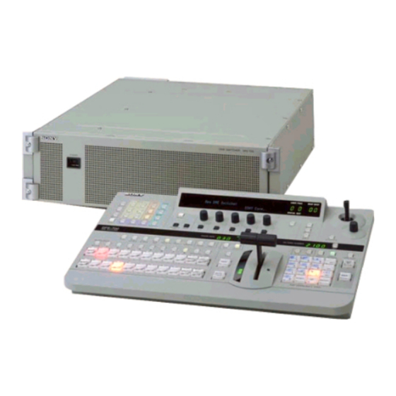
- Page 1 DME SWITCHER DFS-700 DFS-700P DIGITAL/ANALOG INPUT BOARD BKDF-701 ANALOG COMPOSITE INPUT BOARD BKDF-702/702P DIGITAL MULTI EFFECTS BOARD BKDF-711 3D VIDEO MAPPING EFFECTS BOARD BKDF-712 SERVICE MANUAL Volume 1 1st Edition...
- Page 2 2-10. Switch, Indicators, and Volume Controls on Board ......... 2-27 2-10-1. Control Panel ................2-27 2-10-2. Processor .................. 2-28 2-11. Error Indication ..................2-41 2-12. Periodic Inspection ..................2-42 2-12-1. Periodic Replacement Parts ............2-42 2-12-2. Filter Cleaning ................2-42 DFS-700/700P...
- Page 3 4-3-19. Black Burst OUT SC Phase Adjustment ........4-24 4-3-20. Black Burst OUT SYNC Level Adjustment ......4-26 4-3-21. Black Burst OUT Burst Level Adjustment ......4-27 4-3-22. INT SC Frequency Adjustment ..........4-28 4-3-23. INT SCH Phase Adjustment ............ 4-29 DFS-700/700P...
- Page 4 SDI VCO Free-running Frequency Adjustment ...... 4-74 4-6-2. Component Y Level Adjustment ..........4-75 4-6-3. Component Chroma Level Adjustment ........4-76 4-6-4. Input Y/C Delay Adjustment ........... 4-78 4-6-5. Video Input Phase Adjustment..........4-79 4-7. Adjusting the Power Supply Voltage ............4-80 DFS-700/700P...
-
Page 6: Manual Structure
Manual Structure Purpose of this manual This manual is the service manual Vol.1 of the DME Switcher DFS-700/700P and their optional boards. The service manuals (Vol.1 and Vol.2) are intended for use by trained system and service engineers, and describes the information on installing, maintenance, and detailed service. - Page 8 3-203-834-11(1) DME Switcher Operating Instructions Before operating the unit, please read this manual thoroughly and retain it for future reference. DFS-700/700P © 2000 Sony Corporation...
- Page 9 Record these numbers in the spaces provided below. Refer reasonable protection against harmful interference when the Option Boards ..............1-3 to them whenever you call upon your Sony dealer regarding equipment is operated in a commercial environment. This this product. equipment generates, uses, and can radiate radio frequency energy and, if not installed and used in accordance with the Model No.
-
Page 10: Table Of Contents
Table of Contents Chapter 3 Chapter 5 Basic Operation Control From Inserting Characters and Graphics (1) — Title Key ...3-33 Control From the PVE-500 ..........5-1 Editing Control Luminance Key .............. 3-33 Preparations ..............5-2 (Continued) Units Chroma Keying .............. 3-36 Cut Editing ............... - Page 11 Specifications .............. A-64 Glossary ............... A-66 Features of This System Index .................I-1 The Sony DFS-700/700P DME Switcher is a Digital Support for wide range of input/output Multi Effects system, offering high-performance signal formats effects at high image quality. The system consists of a processor unit and control panel.
-
Page 12: Execution
Option Boards Features of This System The DFS-700/700P system has the following option Color correction function Interfacing with editors BKDF-711 2nd Channel DME Board boards. A YUV color correction function is provided for white This system is equipped with I/O interfaces for two This board provides a second DME channel, enabling balance adjustment and general color adjustment. - Page 13 Chapter Location and Function of Parts and Controls Control Panel This section describes the control panel, which is Note divided into several sections, as shown below. See the If you make an error in operation, a warning sound page numbers shown in parenthesis for more details. may occur.
- Page 14 Control Panel 1 Delegation section 2 Primary cross-point bus section 3 Frame memory buttons BACKGROUND 1 BACKGROUND bus buttons BLACK MEMORY VIDEO 1 Delegation buttons TITLE 1 TITLE 2 SUPER BG FRGD 2 MEMORY FRAME FREEZ SOURCE SOURCE FILL AUXILIARY FOREGROUND 2 FOREGROUND bus buttons 2 AUXILIARY buttons...
- Page 15 Control Panel 9 N/R (normal/reverse) button 3 Effect transition section 4 Pattern/numeric keypad To carry out an effect in normal/reverse (i.e. alternating) mode, press this button, turning it on. It This is used for effect pattern selection, transition time lights automatically for animation effects and title 2 Display window mode indicators setting, and other data entry.
- Page 16 Control Panel 5 PATTERN/KEY PAD buttons Changing labels 3 DSK (downstream keyer) button These function as shown in the following table, Press this button, turning it on, to insert the You can change the labels on the buttons, using the 2 DSK section according to the selected mode.
- Page 17 Control Panel 3 EDGE section 4 CCR, LIGHTING, and MATTES buttons 5 SHIFT button MASK button: Press this button to mask off a part This controls the edge effects applied to the boundary CCR (color corrector) button: Press this button to When a button in the menu control section is lit, but of the key source signal.
- Page 18 Control Panel • Changing a setting value preceded by “+” (setup q; Snapshot section 8 Effect control section menu operations) Hold down the corresponding F button (F1 to F5), and turn the control knob. SNAP SHOT • Changing a setting value followed by “+” (user program effect setting operations) 1 SNAP SHOT number display Hold down the corresponding F button (F1 to F5),...
- Page 19 Processor Unit Control Panel 4 HOLD INPUT button Front Panel To hold the primary cross-point bus settings and the qs 25-pin connector (rear panel) auxiliary bus settings (signal selections) fixed when recalling a snapshot, press this button. When you press this button, it lights, and when you recall a snapshot, Power indicator the system is in the hold input mode.
- Page 20 Processor Unit COMPONENT/COMPOSITE (OPTION) 5 to 8 qa REF. (reference) VIDEO IN connectors (BNC- 1 PGM OUT (program output) connectors 7 CLEAN OUT connector (BNC-type) (BNC-type) These output the final program output, that is, the Outputs serial digital signals (270 MHz). Using the type) and 75Ω...
-
Page 21: Basic Operation
Chapter Basic Operation DME Switcher Introduction This section selects two of the many effects provided by the DFS-700/ 700P as examples, and describes the basic flow of operations to use them. It also describes the demonstration function, which automatically executes one hundred sample effects. -
Page 22: Checking
DME Switcher Introduction Procedure Example Operation (1): Wipe In this example we’ll use the AUTO TRANS button, to make a wipe, with the new image appearing from the center of the screen. USER PGM SNAP SHOT TITLE EDGE STATUS EDIT EDITOR TRAIL Setting items... - Page 23 DME Switcher Introduction Press button 9 in the pattern/numeric keypad. Example Operation (2): Picture-in-Picture The button lights, and this selects the wipe assigned to this button (pattern number 24). The PATTERN NUMBER display window Using the fader lever, we’ll insert the foreground image within the shows “0024”.
- Page 24 DME Switcher Introduction In the numeric keypad, press buttons 1, 1, 0, 0, in that order. Procedure The TRANS RATE display window shows “1.1.0.0.”. Dots appear to the lower right of the digits. USER PGM SNAP SHOT TITLE EDGE STATUS EDIT EDITOR TRAIL SHADOW...
- Page 25 ROM in the processor unit. The effects (which by factory default are snapshots 0 to 99) have been chosen to demonstrate the features of the DFS-700/700P as effectively as possible. For maximum effect, the demonstration function uses the signals connected to VIDEO INPUT connectors 1 and 2, and the internal video signal.
- Page 26 DME Switcher Introduction Changing settings Using the Menus • For settings with values shown in letters, press the corresponding one of buttons F1 to F5. This unit incorporates menus for various effect settings and internal color In the text, this is shown as “the F1(SELECT) button,” with the setting matte settings, and also a setup menu for system settings.
- Page 27 Selecting Images Selecting the background image and foreground image Background Image and Foreground Image As the background image and foreground image you can select any of the video signals connected to the VIDEO INPUT 1 to 8 connectors of the Background and foreground in a transition effect processor unit (corresponding to BACKGROUND/FOREGROUND bus In a transition from one image to another, the old image is referred to as...
- Page 28 Selecting Images Switching the internal video signal selected by the INT VIDEO button Previewing the image after an effect is executed To switch the internal video signal selected by pressing the INT VIDEO Select the background image and foreground image, and set up the effect, button on either the background bus or foreground bus, use the following then move the fader lever to the opposite end.
- Page 29 This section describes the types of effects you can use on this system, and Selecting Signals Output to the Auxiliary Bus how to select an effect. Types of Effect Delegation buttons USER PGM SNAP SHOT The DFS-700/700P has more than 450 built-in effect patterns provided as TITLE EDGE STATUS EDIT EDITOR TRAIL standard.
- Page 30 Selecting an Effect Example Effects This section shows as examples the effect patterns (“direct patterns”) Pattern number: 700 which you can access simply by pressing a button in the pattern/numeric Effect type: matrix wipe Motion type: transition keypad. Note that the effect patterns shown below are the factory default assignments, and you can change the patterns assigned to buttons 0 to 9 and P IN P/RST.
- Page 31 Selecting an Effect Nonlinear effects These effects include effects such as ripples, under names such as lens, burst, explosion, swirl, and rings. Pattern number: 2100 Effect type: page turn Motion type: transition The foreground image appears as though progressively covering the background image.
- Page 32 Selecting an Effect 3D mapping effects Selection in Direct Pattern Selection Mode These effects use nonlinear image processing techniques. They include 3D page turn, 3D beveled edge, and so on. In the direct pattern selection mode, pressing any button (other than INS, DEL, UP, DOWN, or ENTER) in the pattern/numeric keypad directly selects an effect pattern.
- Page 33 Selecting an Effect If you enter a wrong number Selection in Pattern Number Specification Mode Before pressing the ENTER button press the P IN P/RST button to cancel the wrong number, then enter the correct number. In the pattern number specification mode, you select the desired effect Note pattern by entering the number.
- Page 34 Modifying the Boundary — Border, Soft Edge, Beveled Edge, and Crop To blur the image boundary You can apply a border to the boundary between the foreground image and background image, or mask unwanted parts of the image. Use the following procedure. There are four effects for modifying the boundary, as follows.
- Page 35 Changing the Pattern Position and Size — Modifying the Boundary — Border, Soft Edge, Beveled Edge, and Crop Location (X)(Y)(Z) Indications in the EDGE menu with square brackets [ ] You can adjust the position and size of an effect pattern when inserting a The parameters in the EDGE menu for functions which are turned off foreground image into the background image.
- Page 36 Modifying the Pattern — User Modifiable Effects Changing the Pattern Position and Size — Location (X)(Y)(Z) To move the pattern in the depth direction (z-axis), turn the Z-knob in User modifiable effects are those effects for which you can modify the the location section.
-
Page 37: (Continued) Luminance Key
Inserting Characters and Graphics (1) — Title Key Modifying the Pattern — User Modifiable Effects Example of user modifiable effect parameters You can insert (or superimpose) text and graphics into the background As an example, if you select mosaic (pattern number 1016), the following image while applying effects. - Page 38 Inserting Characters and Graphics (1) — Title Key In the TITLE section of the menu control section, press a LUM button, Procedure turning it on. To insert text and graphics in a background image by means of a The luminance key menu appears in the menu display. In the following luminance key, use the following procedure.
-
Page 39: Chroma Keying
Inserting Characters and Graphics (1) — Title Key Auto chroma keying Chroma Keying To combine the background image and foreground image by auto chroma In chroma keying, a key signal is created based on a specific reference keying, use the following procedure. color in the foreground image, and used to replace the corresponding parts of the foreground image by the background image. - Page 40 Inserting Characters and Graphics (1) — Title Key Making fine adjustments to the composite image In the TITLE section of the menu control section, press the CRK button, turning it on. Following the manual chroma key procedure (see next page), adjust the hue, clip, and gain for the specified chroma key color.
- Page 41 Inserting Characters and Graphics (1) — Title Key Watching the composite image on the program monitor, in page 1 of Manual chroma key the chroma key menu, adjust the hue, clip, and gain. To combine the background image and foreground image by manual When the background part of the foreground image is not chroma keying, use the following procedure.
- Page 42 Inserting Characters and Graphics (1) — Title Key Watching the composite image on the program monitor, turn the Adjusting the hue range for chroma keying (the “angle” setting) F3(Hue) and F2(Sat) knobs, until the boundary between the background image and foreground image provides a natural match of If there are fluctuations in the background color in the foreground image, it hue and saturation.
-
Page 43: Masking Part Of A Title Key
Inserting Characters and Graphics (2) — Downstream Key Inserting Characters and Graphics (1) — Title Key As its name implies, the downstream key (often abbreviated as DSK) is a Masking Part of a Title Key key which is added downstream the title keying stages, to the already- formed composite image made up of the background and foreground You can apply a rectangular mask, to eliminate unwanted parts of the key. - Page 44 Inserting Characters and Graphics (2) — Downstream Key Select the downstream key fill signal. Procedure 1) Press the PAGE button, and switch to page 1 of the downstream key menu. To insert a downstream key, use the following procedure. Clip Gain INVERT FILL...
- Page 45 Inserting Characters and Graphics (2) — Downstream Key To invert the downstream key source signal Press the F1(TYPE) button, to select the border type. Depending on the desired sense of the key source signal (whether the white or black portions form the key), in page 1 of the downstream key Wide: wide border menu make the following setting.
-
Page 46: Setting Up A Transition
Inserting Characters and Graphics (2) — Downstream Key Setting Up a Transition This section describes how to set the transition time and transition To mask a part of the downstream key direction. You can mask out unwanted portions of a downstream key (text or graphics). -
Page 47: Setting The Transition Direction
Setting Up a Transition Press the ENTER button. Operation of transition effects The dots to the lower right of the digits disappear, confirming the The following figure illustrates the execution of an example transition transition time. effect. In the figure, “B” is the background image and “F” the foreground image. -
Page 48: Executing An Effect
Executing an Effect To execute an effect, after setting the execution direction (normal/reverse), Using the AUTO TRANS button in the effect transition section press the AUTO TRANS button, or move the fader lever. To execute the effect automatically at the preset transition time, press the AUTO TRANS button, turning it on. -
Page 49: Adjusting Color Mattes
Executing an Effect Adjusting Color Mattes You can adjust the color of each color matte individually, and also copy Checking the direction and state of progress of the transition parameters from other color mattes. Whether you are carrying out the effect manually or automatically, the transition indicator on the left of the fader lever (20 LEDs) shows the state of progress of the transition. -
Page 50: Adjusting Image Colors - Color Correction
Adjusting Image Colors — Color Correction Adjusting Color Mattes To copy a matte color The color correction function allows you to adjust the overall color balance To copy the color matte parameters from another color matte, use the of images, or correct the white balance for different lighting color following procedure. - Page 51 Freezing an Input Image — Frame Memory Function Adjusting Image Colors — Color Correction Watching the image on the monitor, turn the F1 to F5 knobs to adjust Using the frame memory function, you can capture a “freeze frame” from the color.
-
Page 52: Freezing An Input Image - Frame Memory Function
Fade-to-Black Freezing an Input Image — Frame Memory Function Recalling a freeze frame saved in memory The fade-to-black allows you to gradually fade the image on the preview In the BACKGROUND or FOREGROUND bus button row, press monitor (the background image) until it is completely black. MEMORY, turning it on. -
Page 53: Advanced Operations
Chapter Advanced Operations Changing Direct Pattern Assignments You can change the effect patterns assigned to the buttons 0 to 9 and P IN P/RST. Doing so allows you to select frequently used patterns simply by pressing the corresponding buttons in direct pattern selection mode. To change the direct pattern assignment To change the direct pattern assignment to the buttons 0 to 9 and P IN P/ RST, use the following procedure. -
Page 54: User Program Effects
Changing Direct Pattern Assignments User Program Effects Use buttons 0 to 9 to enter the pattern number you want to assign to a In addition to the internal effect patterns, you can also create user- button. customized effect patterns. These are referred to as “user program effects.” With standard equipment you can save a maximum of 40 effects. -
Page 55: Types Of User Program Effect
User Program Effects Types of User Program Effect Modification Parameters There are four types of user program effects. The four types must be You can adjust key frames, using the effect control section and location registered saved in the pattern number ranges shown below. section to set the parameters described on pages 4-6 and 4-7. - Page 56 User Program Effects Parameters for linear user program effects (9000 to 9009 and 9100 to 9109) Parameters for nonlinear user program effects (9200 to 9209 and 9300 to 9309) Impression of parameter adjustment Controls and parameters Impression of parameter adjustment Controls and parameters Joystick, Loc-X knob Joystick, Loc-X knob...
- Page 57 User Program Effects Displaying parameter values About the key frame duration The numerical values of the parameters appear in the menu. The KfDur value (key frame duration) for key frame n corresponds to the interval between key frame n and key frame n+1. Therefore, if the settings are as follows: Numerical parameter values Parameter...
-
Page 58: Creating New User Program Effects
User Program Effects Press the EDIT button. Creating New User Program Effects The button lights, the system enters user program edit mode, and the To create a new user program effect, use the following procedure. monitor shows the image (key frame 1) selected on the FOREGROUND bus buttons. -
Page 59: Editing User Program Effects
User Program Effects To change the key frame parameters Editing User Program Effects After carrying out the procedure to step 4 in the section “To recall a user You can recall a created user program effect, and change its parameters, or program effect”... - Page 60 User Program Effects When you have added all the key frames, press the EDIT button. Adding a key frame The button goes off, and the user program effect is resaved with the added key frames. Example: Adding a key frame after key frame 3 Undefined key frames Deleting a key frame Example: Deleting key frame 3...
- Page 61 When the copy is completed, press the EDIT button, turning it off. key frame in a linear effect. • The key frames temporarily saved in numeric buttons are lost when the DFS-700/700P is powered off. 4-16 4-17 Chapter 4 Advanced Operations...
-
Page 62: Executing User Program Effects
User Program Effects Executing User Program Effects Deleting All User Program Effects You execute a user program effect in the same way as a built-in effect, by To delete all user program effects, use the following procedure. entering the pattern number. Transitions between the key frames in user program effect are smooth Press the SET UP button. -
Page 63: Snapshots
Snapshots This unit’s snapshot function allows you to save the control panel state, Saving a Snapshot and recall it whenever necessary. You can save up to one hundred control panel states in snapshot registers To save a snapshot, use the following procedure. in the processor numbered from 0 to 99. -
Page 64: Recalling A Snapshot
Snapshots Use the following procedure. Recalling a Snapshot In the pattern/numeric keypad, press the DIRECT RECALL button, To recall a snapshot, use the following procedure. turning it on. This switches to direct recall mode. SNAP SHOT number display Press the one of buttons 0 to 9 corresponding to the snapshot you want USER PGM SNAP SHOT TITLE... -
Page 65: Reinitializing The Snapshots
Operating Instructions. Downstream key control using GPI signals You can use GPI pulse signals from the PVE-500 to turn the DFS-700/ 700P downstream key function on or off on the falling edge of a pulse. Input the GPI signals to the T2 connector on the DFS-700/700P. -
Page 66: Preparations
BLACK BURST OUT connectors on the DFS-700/700P. Signal flow in A/B roll editing To perform a cut edit by controlling the DFS-700/700P from the PVE-500, use the following procedure. For this operation, refer also to the PVE-500 Operating Instructions. -
Page 67: Control From The Bve-600
Control From the BVE-600 Control From the PVE-500 You can combine the DFS-700/700P with a BVE-600 Editing Control Unit Procedure to carry out A/B roll editing using two players and one recorder. The BVE-600 controls the DFS-700/700P using the GPI trigger signals T1 To perform A/B roll editing by controlling the DFS-700/700P from the and T2. -
Page 68: A/B Roll Editing
Timing of trigger signals in A/B roll editing Note To improve editing accuracy, supply a reference sync signal to the BVE-600 and VCRs from the BLACK BURST OUT connectors on the DFS-700/700P. Signal flow in A/B roll editing Chapter 5 Control From Editing Control Units... -
Page 69: Control From The Bve-900/2000 Series
For details of preread editing, see the section “Preread Editing” (page 5-14). 2000 to turn the DFS-700/700P downstream key function on and off. Input the GPI signals to the T2 connector on the rear panel of the DFS-700/ 700P. (The BVE-2000 can also use 9-pin serial control signals to turn the Connectable editing control units downstream key on and off and to set the transition duration.) -
Page 70: Notes On Operation
GPI signal output to carry out A/B roll editing using two players and one recorder. You can use one GPI signal to execute DFS-700/700P effects, and a Editing point delay second GPI signal to turn the downstream key function on and off. -
Page 71: A/B Roll Editing
To improve editing accuracy, supply a reference sync signal to the editing control unit and the VCRs from the BLACK BURST OUT connectors on the DFS-700/700P. If in page 1 of the setup menu you have set F3(PORTS) to “PVE-500” or “GPI”... -
Page 72: System Connections And Settings
If using a BVE-2000 earlier than Ver. 2.24 or another editor, previewing is not possible. and Settings • It is not possible to set the DFS-700 preread mode from the editor. It must be set manually. For an editor other than the BVE-2000, it is not possible to set the preread mode for the VTR. -
Page 73: Basic System Connections
AC power cord (supplied) 25-pin control cable (supplied) 25-pin connector (rear panel) Video/key signals Control signals DFS-700/700P control panel Black burst signal (reference synchronizing signal) Video signals DFS-700/700P control panel Note Control signals For the cables used for connection to a character generator, check in the instructions supplied with the character generator. -
Page 74: System Connections For Preread Editing
Using an editor with GPI signal support, A/B roll editing controlled by GPI signals is also possible. Note The video from the player VCR is delayed by one frame in the DFS-700/ When using GPI signals 700P, and therefore playback advanced by one frame is required. -
Page 75: Processor
A “P” appears here when P 1/8 PVE500 IN 4 preread editing is on. VIDEO Values Page VIDEO Player VCR A Recorder VCR DFS-700/700P control panel VIDEO System Setup (page 1/8) AUDIO LINE Button Setting Meaning Values VIDEO OUT VIDEO... -
Page 76: System Information Display
Composite: analog composite signals (Appears as “***” when not installed.) To return, press F5(EXIT r). Input number INFO Display software version. VER r DFS-700/700P :x.xx BKDF-712: x.xx With standard Component Component Component Component DATA: x.xx equipment Panel: x.xx With BKDF-701 (Appears as “----”... -
Page 77: Control Panel Setup
Setting DISABL makes the function not available. Warning messages appear in the menu display panel of the control panel Initializing User Settings (page 6/8) when trouble occurs during operation of the DFS-700/700P. Press the F5 (OK) button to erase the message. Button Setting Meaning Values (First value is factory default.) -
Page 78: Effect Type List
Warning Messages Effect Type List The effects provided by the DFS-700/700P are classified as follows. Warning message list Pattern No. Types of effects Reference The number of available patterns page no. The following warning messages are displayed. Varieties in Varieties with... - Page 79 Effect Control Parameter List Effect Type List You can change effect pattern parameters by using the F1 to F5: Menu page 1 Pattern No. Types of effects The number of available patterns Reference page no. pattern adjustment knobs, joystick, and Z-knob on the F6 to F10: Menu page 2 Varieties in Varieties with...
-
Page 80: Effect Control Parameter List
Effect Control Parameter List Effect control parameters (continued) Effect control parameters (continued) Pattern Pattern Effect type and adjustable parameters Effect type and adjustable parameters 1065 Strobe 1280 Real paint, Stained glass F1: Frames displayed per second (Strobe = 0 to 100) F1: Degree of paint effect (Amp = 0 to 100) 1283 1066... - Page 81 Effect Control Parameter List Effect control parameters (continued) Effect control parameters (continued) Pattern Pattern Effect type and adjustable parameters Effect type and adjustable parameters 2260 Ripple 2284 Lens F1: Amplitude of modulation (Amp = 0 to 100) F1: Amplitude of modulation (Amp = 0 to 100) 2269 F2: Frequency of modulation (Freq = 0 to 100) F2: Size of lens (Size = 0 to 100)
- Page 82 Effect Control Parameter List Effect control parameters (continued) Effect control parameters (continued) Pattern Pattern Effect type and adjustable parameters Effect type and adjustable parameters 2ch picture-in-picture (with perspective, horizontal alignment) 2521 2ch picture-in-picture (slide) 2510 F1: Perspective (Pers = 0 to 100) F1: Delay between channels (Delay = 0 to 100) 2513 F2: Y-axis size (Size_Y = 0 to 100)
- Page 83 Effect Control Parameter List Effect control parameters (continued) Effect control parameters (continued) Pattern Pattern Effect type and adjustable parameters Effect type and adjustable parameters 2533 2ch picture-in-picture 2700 3D page turn 2701 F1: Direction of turn (Angle = 0 to 99) 2534 F1: Delay between channels (Delay = 0 to 100) F2: Change in turn direction (Curve = –100 to +100)
- Page 84 Effect Control Parameter List Effect control parameters (continued) Effect control parameters (continued) Pattern Pattern Effect type and adjustable parameters Effect type and adjustable parameters 2710 3D page turn 2730 3D box twist 2711 F1: Direction of turn (Angle = 0 to 100) F3: Area of the part that twists (Area = 0 to 100) F2: Change in turn direction (Curve = –100 to +100) 2739...
- Page 85 Effect Control Parameter List Effect control parameters (continued) Effect control parameters (continued) Pattern Effect type and adjustable parameters Pattern Effect type and adjustable parameters 2826 3D one-picture brick 2820 3D two-picture cube 2827 F1: Amount of X-axis rotation (Rot_X = –100 to +100) 2821 F1: Amount of X-axis rotation (Rot_X = –100 to +100) F2: Amount of Y-axis rotation (Rot_Y = –100 to +100)
- Page 86 Effect Control Parameter List Effect control parameters (continued) Effect control parameters (continued) Pattern Pattern Effect type and adjustable parameters Effect type and adjustable parameters 2840 3D cylinder 2854 3D wave 2841 F1: Amount of X-axis rotation (Rot_X = –100 to +100) 2855 F1: Amount of X-axis rotation (Rot_X = –100 to +100) F2: Amount of Y-axis rotation (Rot_Y = –100 to +100)
-
Page 87: Effect Motion Types
Effect Control Parameter List Effect Motion Types The effects of the DFS-700/700P can be classified by their direction type, Effect control parameters (continued) as follows. Pattern Effect type and adjustable parameters Effects classified by direction type 2871 3D object effects... -
Page 88: Effect Pattern Variant Forms And Decorations
Effect Pattern Variant Forms and Decorations Some effect patterns have attributes that allow you to LOCATE: Location of the pattern EDGE CROP LOCATE LIGHTING TRAIL OPTION Pattern No. TITLE change them, for example by changing the position or XY: X-axis and Y-axis location DS 711 712 adding a border. - Page 89 Effect Pattern Variant Forms and Decorations EDGE CROP LOCATE LIGHTING TRAIL OPTION EDGE CROP LOCATE LIGHTING TRAIL OPTION Pattern No. TITLE Pattern No. TITLE DS 711 712 DS 711 712 √ √ √ √ √ √ √ √ √ 1392 √...
- Page 90 Effect Pattern Variant Forms and Decorations EDGE CROP LOCATE LIGHTING TRAIL OPTION EDGE CROP LOCATE LIGHTING TRAIL OPTION Pattern No. TITLE Pattern No. TITLE DS 711 712 DS 711 712 √ √ √ √ √ √ √ √ √ √ √...
-
Page 91: Effect Pattern Image List
Effect Pattern Image List Effect Pattern Variant Forms and Decorations EDGE CROP LOCATE LIGHTING TRAIL OPTION This section illustrates the effect patterns of the DFS-700/700P. Pattern No. TITLE DS 711 712 How to read the patterns √ √ √ √... - Page 92 Effect Pattern Image List Wipe (continued) Matrix wipe (continued) RANDOM RANDOM RANDOM Mosaic 1000 1001 MOSAIC(8X8) MOSAIC(8X8) MOSAIC(8X8) 1003 1006 HORIZONTAL HORIZONTAL VERTICAL VERTICAL MOSAIC MOSAIC MOSAIC MOSAIC Matrix wipe 1010 1011 VARIABLE VARIABLE VARIABLE MOSAIC MOSAIC MOSAIC VARIABLE 1015 1016 1017 1018...
- Page 93 Effect Pattern Image List Freeze, Strobe, Cinema Sill mirror 1020 1021 1065 1066 1067 (DISSOLVE) (DISSOLVE) (DISSOLVE) B&W STROBE COLOR STROBE STROBE Cropping 1022 1023 (DISSOLVE) (DISSOLVE) 1075 CROPPING (fade) 1024 1025 (DISSOLVE) (DISSOLVE) Picture-in-picture P in P 3D P in P 3D P in P 1026 1027...
- Page 94 Effect Pattern Image List Spotlight Multi-screen FG FG FG 1150 1151 1240 1241 (DISSOLVE) (DISSOLVE) FG FG FG FG FG FG Wave modulation Dynamic mirror 1250 1251 1252 1253 1260 1200 1201 WAVE WAVE WAVE RANDOM 1261 1262 1263 1264 1265 1202 1203...
- Page 95 Effect Pattern Image List Split slide Split slide (continued) 1330 1331 1332 1370 1371 1372 1373 1380 1381 1382 1383 1340 1341 1385 1386 1387 1388 1343 1344 1390 1391 1392 1393 1347 1349 1394 1350 1351 1360 1361 1362 1363 (continued) A-36...
- Page 96 Effect Pattern Image List Compress 2D rotation 1500 1501 1600 1601 1602 1603 1604 1502 1503 1605 1606 1607 1610 1611 1504 1505 1612 1613 1506 1507 2D rotation + Compress + Slide 1508 1510 1511 1512 1620 1630 1513 1514 1515 1520...
- Page 97 Effect Pattern Image List 3D rotation 3D rotation + Compress + Slide (modified) 1700 1701 1702 1703 1762 1760 1765 1704 1705 1706 1707 1770 1780 Door 1730 1731 1732 1740 1781 1782 1783 1800 1741 1742 1802 1806 Split 3D rotation 1750 1751 1752...
- Page 98 Effect Pattern Image List Album turn Flip, Tumble (continued) INT VIDEO 1850 1851 1942 1943 VIDEO INT VIDEO 1853 1945 1852 1944 INT VIDEO 1854 1855 1946 1947 INT VIDEO INT VIDEO Flip, Tumble 1949 1948 VIDEO INT VIDEO INT VIDEO 1900 1901 INT VIDEO...
- Page 99 Effect Pattern Image List Page turn Page turn (modified) PAGE TURN PAGE TURN PAGE TURN PAGE TURN PAGE TURN 2150 2151 2152 2153 2154 2100 2101 2102 2103 (variable) (variable) (variable) (variable) (variable) Split page turn 2104 2105 2106 2107 2160 2161 2108...
- Page 100 Effect Pattern Image List Ripple Amoeba, Melt, Lens 2260 2261 2280 2281 2262 2263 2282 2283 2264 2265 2284 Two-picture slide 2266 2267 2300 2301 2268 2269 2302 2303 Burst, Explosion, Ring, Swirl 2270 2271 2304 2305 2272 2273 2306 2307 Two-picture slide, 2D rotation 2274...
- Page 101 Effect Pattern Image List Two-picture rotation + Compress + Slide Two-picture intersect 2340 2341 2360 2361 2342 2343 2362 2363 2344 2345 2364 2365 2346 2347 2370 2371 2348 2349 2372 2373 2350 2351 2374 2375 2352 2353 2354 2355 2356 2357 A-48...
- Page 102 Effect Pattern Image List Two-picture box Two-picture brick 2380 2381 2400 2401 2382 2383 2402 2403 2384 2385 2404 2405 2386 2387 2406 2407 2388 2389 2410 2411 2390 2391 2412 2413 2392 2393 2414 2415 2394 2395 2416 2417 2418 2419 A-50...
- Page 103 Effect Pattern Image List Two-picture brick (flip type) Masked flip 2420 2421 2480 2481 2422 2423 2482 2483 2424 2425 2484 2485 2426 2427 2486 2487 2428 2429 2488 2489 2430 2431 2490 2491 2432 2433 2492 2493 2434 2435 2494 2495 2436...
- Page 104 Effect Pattern Image List 2ch picture-in-picture 2ch picture-in-picture 2500 2501 2520 2521 2502 2503 2522 2523 2504 2505 2524 2525 2506 2507 2526 2527 2508 2509 2530 2531 2510 2511 2532 2533 2512 2513 2534 Two-picture page turn 2514 2515 2550 2551 2516...
- Page 105 Effect Pattern Image List Split page turn 3D split flip 2560 2561 2630 2631 2562 2563 2632 2633 Multi-cube 2564 2640 2641 3D split 2600 2604 2642 2643 2605 2644 2645 2610 2611 2646 2612 2613 2650 2651 Three-picture multi-cube 2620 2624 2660...
- Page 106 Effect Pattern Image List Special wipe 3D box twist 2690 2691 2730 2731 2692 2732 2733 3D page turn 2734 2735 2700 2701 2736 2737 2702 2703 2738 2739 2704 2705 3D modeling effect 2710 2711 2740 2750 2751 2752 2712 2713 2714...
- Page 107 Effect Pattern Image List 3D beveled edge, Picture-in-picture 3D cylinder, Sphere, Heart 2800 2801 2840 2841 2802 2803 2842 2843 2804 2805 2844 2845 3D modeled edge, Picture-in-picture 3D wave, 3D flag 2810 2811 2850 2851 2812 2813 2852 2853 3D cube, 3D brick 2854 2855...
-
Page 108: To Exchange The Button Labels
To Exchange the Button Labels Effect Pattern Image List After changing a pattern assignment, you can exchange the label on the 3D object effect numeric buttons. Proceed as follows. 2870 2871 Write the new pattern on one of the supplied exchange labels. Insert the supplied tool into the hole at the side of the button and 2872 2873... -
Page 109: Specifications
DFS-700P: 220/240 V AC, Operation manual (1) 50/60 Hz Y: 1.0 Vp-p, 75 ohms, sync Input signals Operating voltage DFS-700: 90 to 130 V AC, 47 to negagive Design and specifications subject to change without 63 Hz R–Y/B–Y: 0.756 Vp-p, 75 ohms notice. -
Page 110: Glossary
Composite signal FOREGROUND bus buttons. key gain control. This is done to See also “downstream key”. In the DFS-700/700P, an output Video signal containing video, obtain the desired blurring of key R–Y signal mode in which the video input of color burst, and sync signals. -
Page 111: Index
Index Connections 6-1 DSK PVW button 2-6 A/B roll editing system 6-5 DSK section 2-6, 2-8 basic system 6-2 A/B roll editing key signal 6-2 BVE-600 5-6 preread editing 6-4 BVE-900/2000 series 5-8 Control from editing control units 5-1 GPI signals 5-12 EDGE section 2-8 PVE-500 5-3 Control knobs 2-10... - Page 112 Index Front panel 2-13 PATTERN ADJ button 2-10 Specifications A-64 FTB indicator 2-4, 3-51 PATTERN/KEY PAD buttons 2-6, 4-1 STATUS display 2-11, 4-10 LAST X/INS 2-6 F1 to F5 buttons 2-10 PATTERN NUMBER display window SUPER BG button 2-2, 3-16 2-5, 3-24 LEARN button 2-11, 4-21 LIGHTING button 2-9...
- Page 113 Printed in Japan Sony Corporation...
Need help?
Do you have a question about the DFS-700 and is the answer not in the manual?
Questions and answers