Table of Contents
Advertisement
Quick Links
Advertisement
Table of Contents

Related Manuals for Falcon 900S Induction G5


Summary of Contents for Falcon 900S Induction G5
- Page 1 USER GUIDE & INSTALLATION INSTRUCTIONS 900S Induction G5...
- Page 2 SLOW BAKED LEG OF LAMB METHOD 1. Preheat the oven to 220 ¡C (for a conventional oven), 200 ¡C (for a fan oven) or gas mark 7. 2. Pull the small sprigs off the rosemary branches and set aside with the garlic. 2.
-
Page 3: Table Of Contents
Technical Data General Oven Tips 10. Warranty/After Sales Service Cooking Table If You Have a Problem Cleaning Your Cooker Notes Out of Warranty Control Panel and Oven Doors Spare Parts Ovens Oven and Divider Cleaning Table Falcon 900S Induction U110267-02... -
Page 5: Before You Start
1. Before You Start... Personal Safety Thank you for buying this cooker. It should give you many years of trouble-free cooking if installed and operated Important information for pacemaker and implanted correctly. insulin pump users: The functions of this hob comply with It is important that you read this section before you start, the applicable European standards on electromagnetic particularly if you have not used an induction cooker before. - Page 6 Always keep combustible materials, e.g. curtains, and Fig.1-1 ammable liquids a safe distance away from your cooker. DO NOT spray aerosols in the vicinity of the cooker ArtNo.312-0001 Not cooking surface while it is on. DO NOT store ammable materials in the storage tray or in the vicinity of this unit.
-
Page 7: Hob Care
Hob Care Fig.1-2 NEVER allow anyone to climb or stand on the hob. NEVER cook directly on the hob surface (Fig.1-1). DO NOT use the hob surface as a cutting board. DO NOT leave utensils, foodstu s or combustible items on the hob when it is not is use (e.g. -
Page 8: Oven Care
Oven Care Fig.1-4 Cooking high moisture content foods can create a ‘steam burst’ when the oven door is opened (Fig.1-4). When opening the oven stand well back and allow any steam to disperse. DO NOT use aluminium foil to cover shelves, linings or the oven roof. -
Page 9: Overview
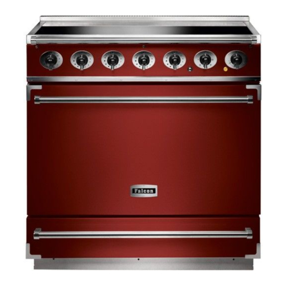
2. Overview Fig.2-1 The Falcon induction cooker (Fig.2-1) has the following Fig.2-2 features: 5 induction cooking zones A control panel A multi-function oven A storage drawer The Hob Use only pans that are suitable for induction hobs. We recommend stainless steel, enamelled steel pans or cast iron pans with enamelled bases. - Page 10 The very best pans have bases that are very slightly curved up when cold (Fig.2-3). If you hold a ruler across the bottom Fig.2-3 you will see a small gap in the middle. When they heat up the metal expands and lies at on the cooking surface. Make sure that the base of the pan is clean and dry to prevent any residue burning onto the hob panel.
- Page 11 Automatic Heat-up, A Automatic Heat-up Time at Power Level 100% (min:sec) This function is available on all of the cooking areas. It allows rapid heating up of the element to bring the selected 0:48 cooking zone up to temperature. Once the zone is at the 2:24 required cooking temperature the power level will reduce automatically to the preset level.
- Page 12 Power Boost Setting, P A & B linked D & E linked Fig.2-8 All of the induction cooking zones have Power Boost available, activated by turning the control knob clockwise until [P ] is shown on the hob control display. Power Boost allows additional power to be made available for each of the cooking zones.
- Page 13 The exposed top element may cook some foods too quickly, Multi-function Oven Functions so we recommend that the food be positioned in the lower Fan Oven half of the oven to cook. The oven temperature may also need This function operates the fan and the heating to be lowered.
-
Page 14: Energy Saving Feature
Energy Saving Feature WARNING! The oven has a divider feature (Fig.2-9). When this is in place only one half of the oven is heated and only the right-hand Take great care when removing the divider NOT to side elements are used. This saves energy and is ideal for scratch the inner glass door surface. -
Page 15: Operating The Oven
The shelf has a small recess on either side (Fig.2-20). To ArtNo.331-0008 - 90SC remove the shelf these must be in line with the shelf brackets ArtNo.326-0014 - Cradle rack (Falcon) grill pan & trivet (Fig.2-21). Lift and pull the shelf forward (Fig.2-22). -
Page 16: Oven Light
Oven Light Fig.2-23 Press the button to turn on the oven lights (Fig.2-23). If one of the oven lights fail, turn o the cooker power supply before you change the bulb. See the ‘Troubleshooting’ section for details on how to change an oven light bulb. Storage ArtNo.320-0023 Oven light USA... -
Page 17: Cooking Tips
3. Cooking Tips Using Your Induction Cooker General Oven Tips If you have not used an induction cooker before please be The wire shelves should always be pushed rmly to the back aware of the following: of the oven. Make sure that the pans you have or buy are suitable for use Baking trays with food cooking on them should be placed on the induction hob. -
Page 18: Cooking Table
4. Cooking Table DocNo.031-0004 - Cooking table - electric & fan single cavity The oven control settings and cooking times given in the table below are intended to be used Top (T) AS A GUIDE ONLY. Individual tastes may require the temperature to be altered to provide a ArtNo.050-0007 preferred result. -
Page 19: Cleaning Your Cooker
5. Cleaning Your Cooker Isolate the electricity supply before carrying out any major Fig.5-1 cleaning. Allow the cooker to cool. NEVER use paint solvents, washing soda, caustic cleaners, biological powders, bleach, chlorine based bleach cleaners, coarse abrasives or salt. DO NOT mix di erent cleaning products – they may react together with hazardous results. -
Page 20: Control Panel And Oven Doors
Control Panel and Oven Doors Fig.5-2 Avoid using any abrasive cleaners including cream cleaners. For best results use liquid detergents. The control panel and control knobs should only be cleaned with a soft cloth wrung out in clean hot soapy water – but take care that no surplus water seeps into the appliance. -
Page 21: Cleaning Table
Cleaning Table Cleaners listed are available from supermarkets or electrical retailers as stated (Table 5-1). For enamelled surfaces use a cleaner that is approved for use on vitreous enamel. Regular cleaning is recommended. For easier cleaning, wipe up any spillages immediately. Hotplate Part Finish... -
Page 22: Troubleshooting
6. Troubleshooting Interference with and repairs to the hob by A crack has appeared in the hob surface unqualified persons are not allowed. Do not try Disconnect the cooker immediately from the power and repair the hob as this may result in injury and supply and arrange for its repair. - Page 23 Food is cooking too slowly, too quickly, or burning Fig.6-1 Cooking times may di er from your previous oven. Check that you are using the recommended temperatures and shelf positions. See the oven cooking ArtNo.324-0005 Oven light bulb guide section of the instructions. The oven control settings and cooking times are intended to be used only as a guide.
-
Page 24: Installation
INSTALLATION Check the appliance is electrically safe when you have nished. 7. Installation You will need the following equipment to complete the Dear Installer cooker installation satisfactorily: Before you start your installation, please complete the details • Multimeter (for electrical checks). below, so that, if your customer has a problem relating to your installation, they will be able to contact you easily. -
Page 25: Positioning The Cooker
INSTALLATION Check the appliance is electrically safe when you have nished. Positioning the Cooker Fig.7-1 The diagrams show the minimum recommended distance 75mm 75mm from the cooker to nearby surfaces (Fig.7-1 and Fig.7-2). 800mm The cooker should not be placed on a base. The hotplate surround should be level with, or above, any adjacent work surface. -
Page 26: Completing The Move
INSTALLATION Check the appliance is electrically safe when you have nished. Removing the Oven Door Fig.7-4 To remove the door, open the door fully. Swivel the locking ‘U’ clips forward to the locking position (Fig.7-4). Grip the sides of the door, lift upwards and then slide the door forwards (Fig.7-5) and remove. -
Page 27: Levelling
INSTALLATION Check the appliance is electrically safe when you have nished. Levelling Stability bracket Fig.7-8 You are recommended to use a spirit level on a shelf in the oven to check for level. Place the cooker in its intended position taking care not to Cooker twist it within the gap between the kitchen units as damage may occur to the cooker or the units. -
Page 28: Electrical Connection
INSTALLATION Check the appliance is electrically safe when you have nished. Electrical Connection Fig.7-10 The cooker must be installed by a quali ed electrician, in accordance with all relevant British Standards/Codes of Practice (in particular BS 7671), or with the relevant national and local regulations. -
Page 29: Final Fitting
INSTALLATION Check the appliance is electrically safe when you have nished. Final Fitting Fig.7-12 Fitting the Plinth Remove the 3 screws for the plinth mounts along the front bottom edge of the cooker (Fig.7-12). Fasten the plinth using these screws (alternative colour screws can be found in the loose parts pack). -
Page 30: Circuit Diagrams
8. Circuit Diagrams Induction Hob Circuit Digram Induction Hob Circuit Diagram Right Rear Left Front Left Rear Centre Right Front Interface board Hob Display Induction unit Code Colour Brown 6 way connector 6 way connector Blue Green... -
Page 31: Oven Circuit Diagram
Oven Circuit Diagram Clear boots r (f) r (f) r (f) r (f) Black boots Code Description Code Description Code Colour Function controller Left-hand top element (outer) Blue Temperature controller Left-hand top element (inner) Brown Right-hand bottom element Left-hand fan element Black Right-hand top element (outer) Left-hand fan... -
Page 32: Technical Data
9. Technical Data INSTALLER: Please leave these instructions with the user. DATA BADGE LOCATION: Inside base drawer of cavity. Remove the drawer (see ‘Overview’ ‘Storage’ for details). COUNTRY OF DESTINATION: GB, IE, FR, NL, DE, SE, AT, BE, CH. Connections Electric 230 / 400 V 50 Hz Dimensions... -
Page 33: Warranty/After Sales Service
10. Warranty/After Sales Service notes If consultation or technical assistance is needed, please provide the local authorised service agent with the purchase If your appliance is outside the 3 year warranty period, our invoice and the product code/serial number. service provider may charge for this visit. This information is on the appliance data badge. - Page 35 Gas Safe registered engineer for gas appliances or an approved electrician for electrical models. CONSUMER SERVICE LINES OPEN: For a competitive quote and to arrange for a Falcon approved Monday to Thursday 8amÐ6pm engineer to attend, call Consumer Services on: 0870 789 5107.
- Page 36 Registered in England and Wales. Registration No. 354715 Registered Office: Juno Drive, Leamington Spa, Warwickshire, CV31 Falcon continuously seeks improvements in specification, design and production of products and thus, alterations take place periodically. Whilst every effort is made to produce up-to-date literature, this booklet should not be regarded as an infallible...
Need help?
Do you have a question about the 900S Induction G5 and is the answer not in the manual?
Questions and answers