
Related Manuals for Falcon 100LT


Summary of Contents for Falcon 100LT
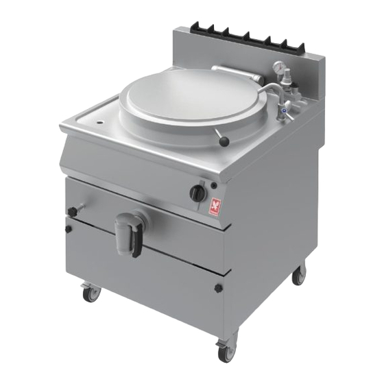
- Page 1 F900 SERIES User, installation and servicing instructions BOILING PAN G9781 Read these instructions before use DATE PURCHASED: MODEL NUMBER: SERIAL NUMBER: DEALER: SERVICE PROVIDER: T100915 REV. 5...
- Page 2 Dear Customer, Thank you for choosing Falcon Foodservice Equipment. This manual can be downloaded from www.falconfoodservice.com or scan here. IMPORTANT: Please keep this manual for future reference. Falcon Foodservice Equipment HEAD OFFICE Wallace View, Hillfoots Road, Stirling. FK9 5PY. Scotland.
- Page 3 These instructions are only valid if the country code appears on the appliance. If the code does not appear on the appliance, refer to the technical instructions for adapting the appliance to the conditions for use in that country.
- Page 4 We recommend supplementary electrical protection with the use of a residual current device (RCD). The appliance has been designed and approved to use Falcon kick plates, non Falcon kick plates could potentially adversely affect the performance of the appliance by restricting the air to the appliance.
-
Page 5: Table Of Contents
CONTENTS Part 1: General reminders and notes 1.1. General reminders 1.2. Technical data 1.3. Construction 1.3.1. Special features for pressure kettles 1.3.2. Special features for indirect kettles 1.4. Installation conformity 1.5. Special requirements for the installation site Part 2: Positioning, installation and maintenance 2.1. Positioning 2.2. Installation 2.2.1. Connection to waterworks 2.2.2. Gas connection procedures 2.3. Checking the operation of the gas system 2.3.1. Control of the gas inlet pressure 2.3.2. Control of primary air flow 2.4. Commissioning and testing 2.5. Conversion to other types of gas 2.5.1. Replacement of injectors for main burners 2.5.2. Replacement of injectors for pilot burner 2.5.3. Minimum output adjustment 2.6. ... - Page 6 Part 4: Figures and details 4.1. Size of appliance and position of connections 4.2. Measuring the inlet pressure 4.3. Gas cock 4.4. Pilot burner 4.5. Main burner 4.6. Primary air regulation 4.7. Controls 4.8. Relief valve (only pressure kettles) 6 ...
-
Page 7: General Reminders
1.1 GENERAL REMINDERS Read the warnings contained in this manual carefully as they provide important information concerning safety during the installation, use and maintenance of the appliance. Read these instructions carefully! Only personnel trained for its specific use should use the equipment. Keep the appliance under observation during use. -
Page 8: Technical Data
900 Height (C) mm 900 Vat diameter mm 600 Table 3 – General water data Specifications Models Description Unit of 100LT & 150LT measurement water connection 3/4" Water pressure 50 – 300 Table 4 – Minimum output setting 100LT & 150LT G20 – 20 mbar 2,5 mbar G30/G31 – 28‐30/37 mbar 3 mbar 8 ... - Page 9 Table 5 – Gas data Lower calorific value Description 100LT & 150LT i Rated heating power Minimum power Gas connection R” ½” G20 – 2H 2,22 kWh/m 9,45 Consumption G30/G31 – 3+ Kg/h 1,65 kWh/kg 12,68 Pilot G20 20 mbar Maximum 3 X 205 Minimum ADJUST. Pilot G30 28‐30/37 mbar ...
-
Page 10: Construction
1.3 CONSTRUCTION Main structure in steel with 4 adjustable height feet. Panels in stainless steel AISI 304, thickness 10-12/10. Cooking pan is stainless steel AISI 316, thickness 20/10. Lid is stainless steel, hinged and spring-balanced in all opening positions. Chrome-plated brass drainage tap. Pan heating controlled by means of high efficiency stainless steel tubular burners resistant to mechanical and thermal stress. -
Page 11: Installation Conformity
1.4 INSTALLATION CONFORMITY When installing the appliance it is necessary to follow and comply with the following regulations: current regulations on the matter; any hygienic-sanitary regulations concerning cooking environments; municipal and/or territorial building regulations and fire prevention prescriptions; current accident prevention guidelines; standards for the use of combustible gas;... -
Page 12: Positioning
SECTION 2 2.1 POSITIONING Remove all the packaging and check that the appliance is in perfect conditions. In case of visible damage, do not connect the appliance and notify the sales point immediately. Remove the PVC protection from the panels. Dispose of packaging according to regulations. -
Page 13: Checking The Operation Of The Gas System
2.3 CHECKING OPERATION OF THE GAS SYSTEM Check that the appliance has been prepared (category and type of gas) equivalent to the family of gas available on site. If not, it is necessary to convert the appliance to whatever is available. -
Page 14: Commissioning And Testing
2.4 COMMISSIONING AND TESTING Once all the connections have been made, the appliance and the overall installation must be checked following the directions given in this manual. Check in particular: that the protective film has been removed from the external surfaces; that connections have been made in accordance with the requirements and directions indicated in this manual;... -
Page 15: Replacement Of Injectors For Pilot Burner
2.5.2 REPLACEMENT OF PILOT BURNER INJECTORS The pilot burner injector is accessed by removing the lower front panel. Remove the side and lower screws. The pilot burner is in the front of the combustion chamber. Undo the screw and replace the injector with an appropriate one. 2.5.3 MINIMUM OUTPUT ADJUSTMENT When appliance has been switched on, set control to minimum position. -
Page 16: Troubleshooting
2.6.1 TROUBLESHOOTING Warning! Only qualified service personnel can perform the operations described below! Warning! Before resetting safety thermostat, it is always necessary to eliminate the problem causing its activation (only for models with indirect heating)! Problem and possible cause Access to components and operation Safety thermostat The content of the pan does not heat: The safety thermostat can be accessed by removing lower... -
Page 17: Instructions For Use
3.2 INSTRUCTIONS FOR USE Before cooking for the first time, wash the pan interior out thoroughly. Warning! Fill pan up to a maximum of 40mm below overflow border, according to the maximum level mark, including the food to be cooked. 3.2.1 FILLING THE JACKET –... -
Page 18: Cleaning And Care Of The Appliance
When this pressure is exceeded, the pressure relief valve on the lid will start operating. On request, the appliance is also available with a pressure gauge to display the pressure inside the kettle. Warning!: After cooking and before opening the lid, all the pressure inside the kettle must be released by lifting the relief valve (see also figure “Relief valve”. -
Page 19: Special Procedures In Case Of Failures
External surfaces should be washed down using a sponge, and hot water with a suitable proprietary cleaner addend. Rinse always thoroughly and dry with a soft cloth. Note for pressure kettles: Do not use detergents containing high percentages of ammonia and sodium to clean the lid gasket. -
Page 20: Size Of Appliance And Position Of Connections
4.1 MODEL DIMENSIONS S. Overflow A. Water connection 3/4" G. Gas connection R ½” in conformity with ISO 7-1 20 ... -
Page 21: Measuring The Inlet Pressure
4.2 MEASURING INLET PRESSURE A. Inlet pressure intake B. Outlet pressure intake 21 ... -
Page 22: Gas Cock
4.3 GAS COCK Thermocouple nut Gas output Outlet pressure intake Inlet pressure intake Rated output adjustment screw Gas inlet Gas connection for pilot burner Minimum output adjustment screw 22 ... -
Page 23: Pilot Burner
4.4 PILOT BURNER Thermocouple Pilot burner Ignition plug Injector Tightness screw 23 ... -
Page 24: Main Burner
4.5 MAIN BURNER Burner Injector Injector pipe 4.6 PRIMARY AIR REGULATION 24 ... -
Page 25: Controls
4.7 CONTROLS Knob OFF position Minimum position Maximum position Pilot flame position 4.8 RELIEF VALVE (Pressure Kettle Only) Operating position Open position 25 ...
Need help?
Do you have a question about the 100LT and is the answer not in the manual?
Questions and answers