Falcon Elan 110 Dual Fuel User's Manual & Installation Instructions
Hide thumbs
Also See for Elan 110 Dual Fuel:
- User manual & installation & service instructions (44 pages) ,
- User manual (41 pages)
Table of Contents
Advertisement
Quick Links
Download this manual
See also:
User Manual
Advertisement
Table of Contents

Subscribe to Our Youtube Channel
Related Manuals for Falcon Elan 110 Dual Fuel


Summary of Contents for Falcon Elan 110 Dual Fuel
- Page 1 USER GUIDE & INSTALLATION INSTRUCTIONS Elan 110 Dual Fuel Australia...
-
Page 3: Table Of Contents
Affix Label Servicing Cleaning Your Cooker Panels & Handrails Essential Information Hotplate Hotplate Burners Controls The Griddle Grill Glide-out Grill Ovens Control Panel and Doors Doors Ovens 10. Circuit Diagram Cleaning Table Troubleshooting 11. Technical Data Elan 110 Dual Fuel U109740-06A... -
Page 5: Before You Start
1. Before You Start... Ventilation Your cooker should give you many years of trouble-free cooking if installed and operated correctly. It is important CAUTION: The use of a gas cooking appliance results that you read this section before you start, particularly if you in the production of heat and moisture in the room have not used a dual fuel cooker before. -
Page 6: Cleaning
Cooking high moisture content Foods for frying should be as dry as possible. Frost on frozen foods can create a ‘steam burst’ foods or moisture on fresh foods can cause hot fat to bubble when an oven door is opened. When up and over the sides of the pan. -
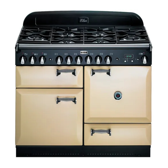
Page 7: Cooker Overview
2. Cooker Overview DocAUS.020-0004 - Overview - 110DF - Elan Fig.2-1 ºC ºC ArtNo.215-0009 - 110 Elan DF The 110 dual fuel cooker (Fig.2-1) has the following features: Fig.2-2 6 hotplate burners including 2 wok burners A control panel A glide-out grill Multi-function oven Fan oven Storage drawer... -
Page 8: Wok Burners
The igniter should spark and light the gas. Keep holding the Fig.2-3 knob pressed in to let the gas through to the burner for about ten seconds. If, when you let go of the control knob, the burner goes out, then the FSD has not been bypassed. -
Page 9: The Wok Cradle
The Wok Cradle Fig.2-9 The wok cradle is designed to fit a Professional 35 cm wok. If you use a different wok, make sure that it fits the cradle. Woks vary very widely in size and shape. It is important that the wok sits down on the pan support –... -
Page 10: The Glide-Out Grill
The Glide-out Grill Fig.2-15 Open the door and pull the grill pan carriage forward using the handle (Fig.2-15). The grill has two elements that allow either the whole area of the pan to be heated or just the right-hand half. Adjust the heat to suit by turning the control knob. -
Page 11: The Ovens
Fan Oven The Ovens This function operates the fan and the heating The clock must be set to the time of day before the ovens element around it. An even heat is produced will work. See the following section on ‘The Clock’ for throughout the oven, allowing you to cook large instructions on setting the time of day. -
Page 12: Operating The Ovens
half of the oven to cook. The oven temperature may also need Fig.2-18 to be lowered. Browning Element This function uses the element in the top of the oven only. It is a useful function for the browning or finishing of pasta dishes, vegetables in sauce, shepherds pie and lasagne, the item to be browned being already hot before switching to the top element. -
Page 13: The Clock
The Clock Fig.2-22 ArtNo.300-0004 2-button clock annotated You can use the timer (Fig.2-22) to turn the ovens on and off. The clock must be set to the time of day before the ovens will work. Note: When using a multi-function oven, first set the clock as required before selecting the oven function and setting the temperature. -
Page 14: Manual Cooking
Use the Adjusting knob to set the ‘cook time’ you need Fig.2-28 Fig.2-29 (Fig.2-28). ArtNo.301-0010 2BC Turn the Timer knob to the [ ] position. The display will ArtNo.301-0008 2BC Setting the cooking time Stopping the oven 2 show the current time of day plus the ‘cook time’ you just set. Use the Adjusting knob to set the ‘stop time’... -
Page 15: Accessories
Accessories Fig.2-35 Oven Shelves Flat shelf Shelf guard In addition to the flat shelves your cooker is supplied with a drop shelf (Fig.2-35). The drop shelf increases the possibilities for oven shelf spacing. Front The oven shelves can be easily removed and refitted. Pull the shelf forward until the back of the shelf is stopped by Shelf guard Drop shelf... -
Page 16: Main Oven Light
Main Oven Light Fig.2-42 Press the button to turn the oven lights on (Fig.2-42). If an oven light fails, turn off the power supply before ArtNo.320-0017 Main oven light changing the bulb. See the ‘Troubleshooting’ section for details on how to change the bulb. Storage The bottom drawer is for storing oven trays and other Fig.2-43... -
Page 17: Cooking Tips
3. Cooking Tips ArtNo.030-0002GB - Cooking tips - electric Tips on Cooking with the Timer General Oven Tips If you want to cook more than one dish, choose dishes that The wire shelves should always be pushed firmly to the back require approximately the same cooking time. -
Page 18: Cooking Table
4. Cooking Table DocNo.031-0004 - Cooking table - electric & fan single cavity The oven control settings and cooking times given in the table below are intended to be used Top (T) AS A GUIDE ONLY. Individual tastes may require the temperature to be altered to provide a preferred result. -
Page 19: Cleaning Your Cooker Essential Information
5. Cleaning Your Cooker Essential Information Fig.5-1 Isolate the electricity supply before carrying out any thorough cleaning. Allow the cooker to cool. NEVER use paint solvents, washing soda, caustic cleaners, biological powders, bleach, chlorine based bleach cleaners, coarse abrasives or salt. DO NOT mix different cleaning products –... -
Page 20: Glide-Out Grill
Glide-out Grill Fig.5-5 Before you remove any of the grill parts for cleaning. make sure that they are cool, or use oven gloves. The grill pan and trivet should be washed in hot soapy water. Alternatively, the grill pan can be washed in a dishwasher. After grilling meats or any foods that soil, leave to soak for a few minutes in the sink immediately after use. -
Page 21: Control Panel And Doors
Control Panel and Doors Fig.5-10 Avoid using any abrasive cleaners including cream cleaners. For best results, use a liquid detergent. The control panel, knobs and doors should only be cleaned with a soft cloth wrung out in clean hot soapy water – but take care that no surplus water seeps into the appliance. -
Page 22: Cleaning Table
Cleaning Table Cleaners listed (Table 5-1) are available from supermarkets or electrical retailers as stated. For enamelled surfaces use a cleaner that is approved for use on vitreous enamel. Regular cleaning is recommended. For easier cleaning, wipe up any spillages immediately. Hotplate Part Finish... -
Page 23: Troubleshooting
6. Troubleshooting Hotplate ignition or hotplate burners faulty Power failure Is the power on? Is the clock illuminated? In the event of a failure in the electrical supply, remember to reset the clock to make sure that the If not, there maybe something wrong with the power timed oven continues to operate. - Page 24 An oven light is not working Fig.6-1 The bulb has probably burnt out. You can buy a replacement bulb (which is not covered under the warranty) from a good electrical shop. Ask for a 15 W – ArtNo.324-0005 Oven light bulb 230 V lamp, FOR OVENS.
-
Page 25: Installation
Andi-Co Australia Pty Ltd. 1 Stamford Road, Oakleigh, VIC 3166 Customer Care Tel: 1300 650 020 Email: service@andico.com.au Name of Appliance Elan 110 Dual Fuel Appliance Serial Number* Fuel Type Dual Fuel Date of Purchase Installer’s Name, Address and Telephone No. -
Page 26: Dear Installer
INSTALLATION Check the appliance is electrically safe and gas sound when you have finished. Dear Installer Provision of Ventilation Before you start your installation, please complete the details This appliance is not connected to a combustion products below, so that, if your customer has a problem relating to evacuation device. - Page 27 INSTALLATION Check the appliance is electrically safe and gas sound when you have finished. You will need the following equipment to complete the Checking the Parts: cooker installation satisfactorily: 4 pan supports Griddle plate • Flexible gas hose. • Gas pressure tester/manometer. •...
-
Page 28: Positioning The Cooker
INSTALLATION Check the appliance is electrically safe and gas sound when you have finished. Positioning the Cooker Fig.7-1 The diagram (Fig.7-1) shows the minimum recommended distance from the cooker to nearby surfaces as given in AS 5601. *Any splashback must be fitted in accordance with the manufacturers instructions. -
Page 29: Moving The Cooker
INSTALLATION Check the appliance is electrically safe and gas sound when you have finished. Moving the Cooker Fig.7-3 On no account try and move the cooker while it is plugged into the electricity supply. The cooker is very heavy, so take great care. We recommend that two people manoeuvre the cooker. -
Page 30: Fitting The Stability Bracket And Chain
INSTALLATION Check the appliance is electrically safe and gas sound when you have finished. Fitting the Stability Bracket and Chain Fig.7-7 Stability bracket A stability bracket and chain MUST be fitted when the cooker is connected to a flexible gas supply. Unless properly installed, the cooker could be tipped by Cooker leaning on the door. -
Page 31: Gas Connection
INSTALLATION Check the appliance is electrically safe and gas sound when you have finished. Gas Connection Fig.7-10 Gas inlet Must be in accordance with the relevant standards. The gas supply needs to terminate with a threaded fitting ½”. The inlet connector is located just below the hotplate level at the rear of the cooker. -
Page 32: Electrical Connection
INSTALLATION Check the appliance is electrically safe and gas sound when you have finished. Electrical Connection Fig.7-11 This appliance must be installed by a qualified electrician to comply with the relevant regulations (AS/NZS 60335.2.6) and also the local electricity supply company requirements. -
Page 33: Final Checks
INSTALLATION Check the appliance is electrically safe and gas sound when you have finished. Final Checks Fig.7-15 Note: The clock must be set before the ovens will work. See ‘The Clock’ section for instructions on setting the time of day. Hotplate Check Check each burner in turn. -
Page 34: Conversion To Lp Gas
WARNING – SERVICING TO BE CARRIED OUT ONLY BY AN AUTHORISED PERSON Disconnect from electricity and gas before servicing. Check appliance is safe when you have finished. 8. Conversion to LP Gas Conversion from Natural Gas (1.0 kPa) Fig.8-1 to LPG X Propane (2.75 kPa) A suitably competent person must perform the conversion. -
Page 35: Set The Governor
WARNING – SERVICING TO BE CARRIED OUT ONLY BY AN AUTHORISED PERSON Disconnect from electricity and gas before servicing. Check appliance is safe when you have finished. Set the Governor Fig.8-4 Unscrew the governor’s brass top. In the base of the brass top is a plastic snap-in converter device (Fig.8-4). -
Page 36: Servicing
WARNING – SERVICING TO BE CARRIED OUT ONLY BY AN AUTHORISED PERSON Disconnect from electricity before servicing. Check appliance is safe when you have finished. 9. Servicing BEFORE SERVICING ANY GAS CARRYING COMPONENTS TURN OFF THE GAS SUPPLY ArtNo.210-0009 - Classic removing the handles Check the appliance is gas sound after completion of service. -
Page 37: Controls
WARNING – SERVICING TO BE CARRIED OUT ONLY BY AN AUTHORISED PERSON Disconnect from electricity before servicing. Check appliance is safe when you have finished. 2.6 To Remove or Change a Hotplate Burner Remove the 2 rear hotplate fixing screws ‘B’ on the cooker back under the flue grille, and the 4 front DISCONNECT FROM THE ELECTRICITY SUPPLY. -
Page 38: Grill
WARNING – SERVICING TO BE CARRIED OUT ONLY BY AN AUTHORISED PERSON Disconnect from electricity before servicing. Check appliance is safe when you have finished. 3.3 To Remove the Electronic Timer DISCONNECT FROM THE ELECTRICITY SUPPLY. Pull off the timer control button(s) and remove the control panel (see 1.2). - Page 39 WARNING – SERVICING TO BE CARRIED OUT ONLY BY AN AUTHORISED PERSON Disconnect from electricity before servicing. Check appliance is safe when you have finished. Feed the thermostat capillary clear of the oven. Fig.9-6 Disconnect the wires from the thermostat and undo the 2 fixings that secure the control to the mounting plate.
-
Page 40: Doors
WARNING – SERVICING TO BE CARRIED OUT ONLY BY AN AUTHORISED PERSON Disconnect from electricity before servicing. Check appliance is safe when you have finished. 5.6 To Remove the Left-hand Oven Bottom and Top Fig.9-8 Elements DISCONNECT FROM THE ELECTRICITY SUPPLY. Bottom Element Pull the cooker forward to access the cover boxes at the rear of the unit. - Page 41 WARNING – SERVICING TO BE CARRIED OUT ONLY BY AN AUTHORISED PERSON Disconnect from electricity before servicing. Check appliance is safe when you have finished. 6.4 To Replace an Oven Door Outer Panel Fig.9-14 Move the cooker forward to gain access to the sides. Open the oven door slightly and remove the front panel fixing screws from the door sides –...
-
Page 42: Circuit Diagram
10. Circuit Diagram P095199 P028728 The connections shown in the circuit diagram are for single-phase. The ratings are for 230 V 50 Hz. Code Description Code Description Code Colour Grill control Right-hand fan oven thermostat Blue Left-hand grill element Right-hand fan oven front switch Brown Right-hand grill element Right-hand fan oven element... -
Page 43: Technical Data
11. Technical Data This cooker is designed for use on Natural gas, although a conversion for LP (LPG X Propane (2.54 kPa)) gas is packed with the cooker. INSTALLER: Please leave these instructions with the User. DATA BADGE LOCATION : Cooker back, serial number repeater badge below oven door opening. COUNTRY OF DESTINATION: Australia Connection &... - Page 44 Clarence Street, Royal Leamington Spa, Warwickshire, CV31 2AD, England. Tel: +44 (0) 1926 457400 Fax: +44 (0) 1926 450526 E-mail: consumers@falconappliances.co.uk...
Need help?
Do you have a question about the Elan 110 Dual Fuel and is the answer not in the manual?
Questions and answers