Falcon Classic toledo 110 dual fuel User's Manual & Installation Instructions
Cooker
Hide thumbs
Also See for Classic toledo 110 dual fuel:
- Instructions for use and installation (52 pages) ,
- User manual & installation & service instructions (44 pages) ,
- User's manual & installation instructions (44 pages)
Table of Contents
Advertisement
Advertisement
Table of Contents

Related Manuals for Falcon Classic toledo 110 dual fuel


Summary of Contents for Falcon Classic toledo 110 dual fuel
-
Page 1: User Guide
110 Dual Fuel User Guide & Installation Instructions U108600-07 Australia... -
Page 2: Table Of Contents
Contents Before you Start... Installation Installation and Maintenance Service and Spares Peculiar Smells Dear Installer If You Smell Gas Provision of Ventilation Ventilation Location of Cooker Personal Safety Conversion Cleaning Positioning the Cooker Moving the Cooker Cooker Overview Fitting the Stability Bracket and Chain Hotplate Burners Fitting the Restraining Chain Wok Burner... -
Page 3: Before You Start
1. Before You Start... Ventilation This User Guide covers a number of di erent models. Although some of the illustrations will look di erent to your CAUTION: The use of a gas cooking appliance results particular model the functions will be the same. We hope the in the production of heat and moisture in the room meaning is clear. -
Page 4: Cleaning
Cooking high moisture content DO NOT use water on grease res and never pick up a aming pan. Turn the controls o and then foods can create a ‘steam burst’ smother a aming pan on a surface unit by covering when an oven door is opened. -
Page 5: Cooker Overview
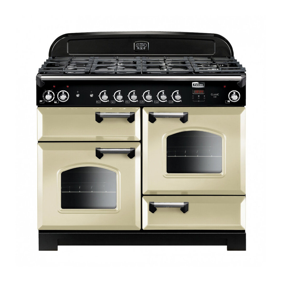
2. Cooker Overview DocNo.020-0013 - Overview - 110DF - Classic, RM & Toledo lidded Fig.2-1 ArtNo.212-0002 - 110 Classic ceramic front view The 110 dual fuel cooker (Fig.2-1) has the following features: Fig.2-2 5 hotplate burners including a warmer and wok burner A control panel A grill Main conventional oven... -
Page 6: Wok Burner
The igniter should spark and light the gas. Keep holding the Fig.2-3 knob pressed in to let the gas through to the burner for about ten seconds. If, when you let go of the control knob, the burner goes out, then the FSD has not been bypassed. -
Page 7: The Wok Cradle
The Wok Cradle Fig.2-9 The wok cradle is designed to t a 35 cm wok. If you use a di erent wok, make sure that it ts the cradle. Woks vary very widely in size and shape. It is important that the wok sits down on the pan support –... -
Page 8: Warmer
Warmer Fig.2-15 On the right of the hob is the warmer (Fig.2-15). Use the warmer for keeping food warm while the nal touches are put to a meal. Turn the control knob counter-clockwise to the ‘On’ position. For best results, preheat a covered serving dish for 10 minutes before adding food to it. -
Page 9: The Ovens
The Ovens Fig.2-19 The clock must be set to the time of day before the ovens will work. See the following section on ‘The Clock’ for instructions on setting the time of day. References to ‘left-hand’ and ‘right-hand’ ovens apply as viewed ArtNo.210-0002 - from the front of the appliance. -
Page 10: The Clock
The Clock Fig.2-21 You can use the timer (Fig.2-21) to turn the ovens on and o . The clock must be set to the time of day before the ovens will work. Setting the Time of Day ArtNo.302-0002 - 6BC annotated When the clock is rst connected the display ashes ( 0.00 ) ... -
Page 11: Key Lock
AUTO is Showing, You Want to Reset to Manual Fig.2-31 Fig.2-32 Cooking To return to manual cooking from any automatic setting, the ‘cook period’ must be cancelled. Press and hold the [] button and then press the [–] button until the display reads ArtNo.302-0009 - Activating ArtNo.302-0008 - the key lock 2... -
Page 12: Accessories
Accessories Fig.2-36 Oven Shelves Shelf guard The oven shelves (Fig.2-36) can be easily removed and re tted. Pull the shelf forward until the back of the shelf is stopped by the shelf stop bumps in the oven sides (Fig.2-37). Front Lift up the front of the shelf so the back of the shelf will pass under the shelf stop and then pull the shelf forward (Fig.2-38). -
Page 13: Cooking Tips
3. Cooking Tips Tips on Cooking with the Timer General Oven Tips If you want to cook more than one dish, choose dishes that The wire shelves should always be pushed rmly to the back require approximately the same cooking time. However, of the oven. -
Page 14: Cooking Table
4. Cooking Table DocNo.031-0004 - Cooking table - electric & fan single cavity The oven control settings and cooking times given in the table below are intended to be used AS A GUIDE ONLY. Individual tastes may require the temperature to be altered to provide a preferred result. -
Page 15: Cleaning Your Cooker
5. Cleaning Your Cooker Isolate the electricity supply before carrying out any Fig.5-1 thorough cleaning. Allow the cooker to cool. NEVER use paint solvents, washing soda, caustic cleaners, biological powders, bleach, chlorine based bleach cleaners, coarse abrasives or salt. DO NOT mix di erent cleaning products – they may react together with hazardous results. -
Page 16: Grill
Grill Fig.5-5 The grill pan and trivet should be washed in hot soapy water. Alternatively, the grill pan can be washed in a dishwasher. After grilling meats or any foods that soil, leave to soak for a few minutes immediately after use. Stubborn particles may be removed from the trivet using a nylon brush. -
Page 17: Cleaning Table
Cleaning Table Removing the Main Oven Linings Some of the lining panels can be removed for cleaning. You Cleaners listed (Table 5-1) are available from supermarkets or will need to remove the shelves before removing the panels. electrical retailers as stated. Each side of the oven is xed with four xing screws. -
Page 18: Troubleshooting
6. Troubleshooting Hotplate ignition or hotplate burners faulty Power failure Is the power on? Is the clock illuminated? In the event of a failure in the electrical supply, remember to reset the clock to make sure that the If not, there maybe something wrong with the power timed oven continues to operate. - Page 19 An oven light is not working Fig.6-1 The bulb has probably burnt out. You can buy a replacement bulb (which is not covered under the warranty) from a good electrical shop. Ask for a 15 W – ArtNo.324-0005 Oven light bulb 230 V lamp, FOR OVENS.
-
Page 20: Installation
INSTALLATION Check the appliance is electrically safe and gas sound when you have nished. 7. Installation Service and Spares Firstly, please complete the appliance details below and keep them safe for future reference – this information will enable us to accurately identify the particular appliance and help us to help you. Filling this in now will save time and inconvenience if you later have a problem with the appliance. -
Page 21: Dear Installer
INSTALLATION Check the appliance is electrically safe and gas sound when you have nished. Dear Installer Provision of Ventilation Before you start your installation, please complete the details This appliance is not connected to a combustion products below, so that, if your customer has a problem relating to evacuation device. - Page 22 INSTALLATION Check the appliance is electrically safe and gas sound when you have nished. Checking the Parts: You will need the following equipment to complete the cooker installation satisfactorily: 3 pan supports Griddle plate • Flexible gas hose. • Gas pressure tester/manometer. •...
-
Page 23: Positioning The Cooker
INSTALLATION Check the appliance is electrically safe and gas sound when you have nished. Positioning the Cooker Fig.7-1 The diagram (Fig.7-1) shows the minimum recommended distance from the cooker to nearby surfaces as given in AS 5601. Overhead – Measurement A The minimum height of any surface above the cooker is 650 mm above the hotplate. -
Page 24: Moving The Cooker
INSTALLATION Check the appliance is electrically safe and gas sound when you have nished. Moving the Cooker Fig.7-3 On no account try and move the cooker while it is plugged into the electricity supply. The cooker is very heavy, so take great care. We recommend that two people manoeuvre the cooker. -
Page 25: Fitting The Stability Bracket And Chain
INSTALLATION Check the appliance is electrically safe and gas sound when you have nished. Fitting the Stability Bracket and Chain Fig.7-6 Stability bracket A stability bracket and chain MUST be tted when the cooker is connected to a exible gas supply. Unless properly installed, the cooker could be tipped by Cooker leaning on the door. -
Page 26: Levelling
INSTALLATION Check the appliance is electrically safe and gas sound when you have nished. Levelling Fig.7-9 You are recommended to use a spirit level on a shelf in one of the ovens to check for level. Place the cooker in its intended position taking care not to twist it within the gap between the kitchen units as damage ArtNo.215-0026 - Handle gaskets fixed may occur to the cooker or the units. -
Page 27: Pressure Testing
INSTALLATION Check the appliance is electrically safe and gas sound when you have nished. Gas Connection Fig.7-12 Must be in accordance with the relevant standards. The gas supply needs to terminate with a down-facing threaded tting ½” connection. The inlet connector is located just below the hotplate level at the rear of the cooker. -
Page 28: Electrical Connection
INSTALLATION Check the appliance is electrically safe and gas sound when you have nished. Electrical Connection Fig.7-13 This appliance must be installed by a quali ed electrician to comply with the relevant regulations (AS/NZS 60335.2.6) and also the local electricity supply company requirements. -
Page 29: Final Checks
INSTALLATION Check the appliance is electrically safe and gas sound when you have nished. Final Checks Fig.7-17 Hotplate Check Check each burner in turn (refer to the ‘Hotplate Burners’ section at the front of the instructions). Grill Check Turn on the grill control and check that the grill heats up. Oven Check Set the clock as described earlier in the instructions, and then turn on the ovens. -
Page 30: Conversion To Lp Gas
WARNING – SERVICING TO BE CARRIED OUT ONLY BY AN AUTHORISED PERSON Disconnect from electricity and gas before servicing. Check appliance is safe when you have nished. 8. Conversion to LP Gas Conversion from Natural Gas (1.0 kPa) Fig.8-1 to LPG X Propane (2.75 kPa) A suitably competent person must perform the conversion. - Page 31 WARNING – SERVICING TO BE CARRIED OUT ONLY BY AN AUTHORISED PERSON Disconnect from electricity and gas before servicing. Check appliance is safe when you have nished. Set the Governor Fig.8-4 Unscrew the governor’s brass top. In the base of the brass top is a plastic snap-in converter device (Fig.8-4).
-
Page 32: Grill
WARNING – SERVICING TO BE CARRIED OUT ONLY BY AN AUTHORISED PERSON Disconnect from electricity before servicing. Check appliance is safe when you have nished. 9. Servicing BEFORE SERVICING ANY GAS CARRYING Fig.9-1 COMPONENTS TURN OFF THE GAS SUPPLY Check the appliance is gas sound after completion of service. - Page 33 WARNING – SERVICING TO BE CARRIED OUT ONLY BY AN AUTHORISED PERSON Disconnect from electricity before servicing. Check appliance is safe when you have nished. Right-hand tray 2.5 To Replace a Hotplate Burner From the rear remove the screws securing the ue grill DISCONNECT FROM THE ELECTRICITY SUPPLY.
- Page 34 WARNING – SERVICING TO BE CARRIED OUT ONLY BY AN AUTHORISED PERSON Disconnect from electricity before servicing. Check appliance is safe when you have nished. 3.2 To Replace the Clock Fig.9-4 DISCONNECT FROM THE ELECTRICITY SUPPLY. Remove the control panel (see 1.1). Pull o the timer control buttons.
-
Page 35: Ovens
WARNING – SERVICING TO BE CARRIED OUT ONLY BY AN AUTHORISED PERSON Disconnect from electricity before servicing. Check appliance is safe when you have nished. Remove the screws securing the electric cover to the Fig.9-5 back sheet, and then remove cover and disconnect the terminals from the rear. -
Page 36: Doors
WARNING – SERVICING TO BE CARRIED OUT ONLY BY AN AUTHORISED PERSON Disconnect from electricity before servicing. Check appliance is safe when you have nished. Fit the replacement control and re-assemble in the Fig.9-6 reverse order. 5.5 To Remove the Right-hand Oven Element DISCONNECT FROM THE ELECTRICITY SUPPLY. - Page 37 WARNING – SERVICING TO BE CARRIED OUT ONLY BY AN AUTHORISED PERSON Disconnect from electricity before servicing. Check appliance is safe when you have nished. 6.2 To Replace an Oven Door Fig.9-11 Centreline of hinge pin Open the oven door. Support the door and loosen the two screws securing the upper hinge and gasket to the cooker front (Fig.9-9).
-
Page 38: Circuit Diagram
10. Circuit Diagram P095199 P025635 P093292 The connections shown in the circuit diagram are for single-phase. The ratings are for 230 V 50 Hz. Code Description Code Colour Code Description Grill control Blue Warmer control Grill element left-hand side Brown Warmer Grill element right-hand side Black... -
Page 39: Technical Data
11. Technical Data DocAUS.101-0024 - Technical data - DF 110 - Classic-Toledo This cooker is designed for use on natural gas but can be used converted to LP (Propane X (2.54 kPa)). A conversion kit from Natural Gas to Propane is supplied with the cooker. INSTALLER: Please leave these instructions with the user. - Page 40 Clarence Street, Royal Leamington Spa, Warwickshire, CV31 2AD, England. Tel: +44 (0) 1926 457400 Fax: +44 (0) 1926 450526 E-mail: consumers@falconappliances.co.uk...
Need help?
Do you have a question about the Classic toledo 110 dual fuel and is the answer not in the manual?
Questions and answers