Falcon Classic Deluxe 90 Dual Fuel User's Manual & Installation Instructions
Hide thumbs
Also See for Classic Deluxe 90 Dual Fuel:
- User's manual & installation instructions (40 pages)
Table of Contents
Advertisement
Advertisement
Table of Contents

Related Manuals for Falcon Classic Deluxe 90 Dual Fuel


Summary of Contents for Falcon Classic Deluxe 90 Dual Fuel
- Page 1 USER GUIDE & INSTALLATION INSTRUCTIONS Classic Deluxe 90 Dual Fuel Australia...
-
Page 2: Table Of Contents
Contents Before You Start... Troubleshooting Installation and Maintenance Installation Peculiar Smells Service and Spares If You Smell Gas Dear Installer Ventilation Provision of Ventilation Personal Safety Location of Cooker Cooker Care Conversion Cleaning Positioning the Cooker Cooker Overview Moving the Cooker Hotplate Burners Completing the Move Wok Burner... -
Page 3: Before You Start
1. Before You Start... If You Smell Gas Thank you for buying a Falcon cooker. It should give you many years of trouble-free cooking if installed and operated • DO NOT turn electric switches on or off correctly. It is important that you read this section before •... -
Page 4: Cooker Care
When the oven is on, DO NOT leave the oven door NEVER leave a chip pan unattended. Always heat fat open for longer than necessary – otherwise, the slowly, and watch as it heats. Deep fry pans should control knobs may become very hot. be only one third full of fat. -
Page 5: Cooker Overview
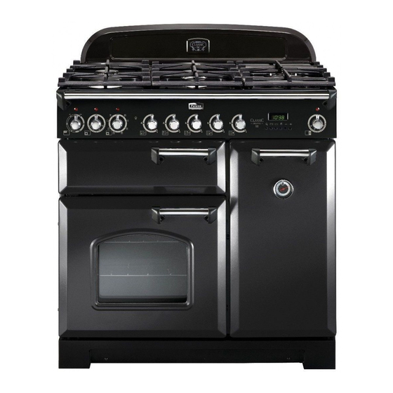
2. Cooker Overview DocNo.020-0002 - Overview - 90 Ceramic - Generic Fig.2-1 LASSI DELUXE The 90 dual fuel cooker (Fig.2-1) has the following features: Fig.2-2 5 hotplate burners including a wok burner A control panel A glide-out grill A main programmable multi-function oven. Tall fan oven Hotplate Burners The drawing by each of the central knobs indicates which... -
Page 6: Wok Burner
The igniter should spark and light the gas. Keep holding the Fig.2-3 knob pressed in to let the gas through to the burner for about ten seconds. If, when you let go of the control knob, the burner goes out, then the FSD has not been bypassed. -
Page 7: The Wok Cradle
The Wok Cradle Fig.2-9 The wok cradle is designed to fit a Professional 35 cm wok. If you use a different wok, make sure that it fits the cradle. Woks vary very widely in size and shape. It is important that the wok sits down on the pan support –... -
Page 8: The Glide-Out Grill
The Glide-out Grill Fig.2-15 Open the door and pull the grill pan carriage forward using the handle (Fig.2-15). The grill has two elements that allow either the whole area of the pan to be heated or just the right-hand half. Adjust the heat to suit by turning the knob. -
Page 9: The Ovens
The Ovens Function The clock must be set to the time of day before the left- Rapid response To quickly heat up the oven hand oven will work. See the following section on ‘The Clock’ for instructions on setting the time of day. To thaw small items in the oven without Defrost heat... - Page 10 It is also possible to bake on two shelves at one time, Multi-function Oven Functions although they will need to be swapped over during the Rapid Response cooking time, as the heat at the top of the oven is greater The Rapid Response setting enables you to preheat than at the base, when using this function.
-
Page 11: The Clock
Make sure that dairy foods, meat and poultry are completely Fig.2-18 defrosted before cooking. Operating the Ovens Fan Oven Turn the oven knob to the desired temperature (Fig.2-18). ArtNo.235-0004 - Classic DL oven 1 The oven indicator light will glow until the oven has reached the temperature selected. - Page 12 Once the ‘stop time’ is reached, the beeper sounds. To stop the Fig.2-24 Fig.2-25 beep turn the oven control knob to 0 first and then press [ B ] once; press [ B ] again to return to manual cooking. To Start and Stop the Oven Automatically ArtNo.302-0005 - ArtNo.302-0005a -...
-
Page 13: Accessories
Accessories Fig.2-35 Oven Shelves – Left-hand (Main) Oven Flat shelf Shelf guard In addition to the flat shelf, the cooker is supplied with a drop shelf (Fig.2-35). The drop shelf increases the possibilities for oven shelf spacing. Front The oven shelves can be easily removed and refitted. Pull the shelf forward until the back of the shelf is stopped by Shelf guard Drop shelf... -
Page 14: Cooking Tips
3. Cooking Tips Tips on Cooking with the Timer General Oven Tips If you want to cook more than one dish, choose dishes that The wire shelves should always be pushed firmly to the back require approximately the same cooking time. However, of the oven. -
Page 15: Cooking Table
4. Cooking Table DocNo.031-0004 - Cooking table - electric & fan single cavity The oven control settings and cooking times given in the table below are intended to be used Top (T) AS A GUIDE ONLY. Individual tastes may require the temperature to be altered to provide a preferred result. -
Page 16: Cleaning Your Cooker
5. Cleaning Your Cooker Essential Information Fig.5-1 Isolate the electricity supply before carrying out any thorough cleaning. Allow the cooker to cool. NEVER use paint solvents, washing soda, caustic cleaners, biological powders, bleach, chlorine based bleach cleaners, coarse abrasives or salt. DO NOT mix different cleaning products –... -
Page 17: The Griddle
The Griddle Fig.5-5 Always clean the griddle after use. Allow it to cool completely before removing. Immerse the griddle plate in hot soapy water. Use a soft cloth or, for stubborn stains, a nylon washing up brush. Note: If the griddle is washed in a dishwasher then some dishwasher residue may appear on the back. -
Page 18: Ovens
Ovens Fig.5-10 ‘Cook & Clean’ Panels The main oven has panels which have been coated with a special enamel that partly cleans itself. This does not stop all marks on the lining, but helps to reduce the amount of manual cleaning needed. The ‘Cook &... -
Page 19: Cleaning Table
Cleaning Table Cleaners listed (Table 5-1) are available from supermarkets or electrical retailers as stated. For enamelled surfaces use a cleaner that is approved for use on vitreous enamel. Regular cleaning is recommended. For easier cleaning, wipe up any spillages immediately. Hotplate Part Finish... -
Page 20: Troubleshooting
6. Troubleshooting Hotplate ignition or hotplate burners faulty Power failure Is the power on? Is the clock illuminated? In the event of a failure in the electrical supply, remember to reset the clock to make sure that the If not, there maybe something wrong with the power timed oven continues to operate. - Page 21 An oven light is not working Fig.6-1 The bulb has probably burnt out. You can buy a replacement bulb (which is not covered under the warranty) from a good electrical shop. Ask for a 15 W – ArtNo.324-0005 Oven light bulb 230 V lamp, FOR OVENS.
-
Page 22: Installation
Andi-Co Australia Pty Ltd. 1 Stamford Road, Oakleigh, VIC 3166 Customer Care Tel: 1300 650 020 Email: service@andico.com.au Name of Appliance Classic Deluxe 90 Dual Fuel Appliance Serial Number* Fuel Type Dual Fuel Date of Purchase Installer’s Name, Address and Telephone No. -
Page 23: Dear Installer
INSTALLATION Check the appliance is electrically safe and gas sound when you have finished. Dear Installer Provision of Ventilation Before you start your installation, please complete the details This appliance is not connected to a combustion products below, so that, if your customer has a problem relating to evacuation device. - Page 24 INSTALLATION Check the appliance is electrically safe and gas sound when you have finished. You will need the following equipment to complete the Checking the Parts: cooker installation satisfactorily: 3 pan supports Griddle plate • Stability bracket: If the cooker is to be supplied with gas through a flexible hose, a stability bracket or chain MUST be fitted.
-
Page 25: Positioning The Cooker
INSTALLATION Check the appliance is electrically safe and gas sound when you have finished. Positioning the Cooker ArtNo.090-0009 - 90 2BC cooker min spacings Fig.7-1 Fig.7-1 shows the minimum recommended distance from the cooker to nearby surfaces. 75 mm 75 mm 650 mm The cooker should not be placed on a base. -
Page 26: Completing The Move
INSTALLATION Check the appliance is electrically safe and gas sound when you have finished. Lowering the Two Rear Rollers Fig.7-5 To adjust the height of the rear of the cooker, first fit a 13 mm spanner or socket wrench onto the hexagonal adjusting nut (Fig.7-5). -
Page 27: Repositioning The Cooker Following Connection
INSTALLATION Check the appliance is electrically safe and gas sound when you have finished. Repositioning the Cooker Following Connection If you need to move the cooker once it has been connected then you need to unplug it and, having gripped under the fascia panel and lifted the front of the cooker slightly (Fig.7-6), you need to check behind the cooker to make sure that the gas hose is not caught. -
Page 28: Gas Connection
INSTALLATION Check the appliance is electrically safe and gas sound when you have finished. Gas Connection Fig.7-10 Must be in accordance with the relevant standards. Gas inlet The gas supply needs to terminate with a threaded fitting ½”. The inlet connector is located just below the hotplate level at the rear of the cooker. -
Page 29: Electrical Connection
INSTALLATION Check the appliance is electrically safe and gas sound when you have finished. Electrical Connection Fig.7-11 This appliance must be installed by a qualified electrician to comply with the relevant regulations (AS/NZS 60335.2.6) and also the local electricity supply company requirements. -
Page 30: Final Checks
INSTALLATION Check the appliance is electrically safe and gas sound when you have finished. Final Checks Fig.7-15 Hotplate Check Check each burner in turn (refer to the ‘Hotplate Burners’ section at the front of the instructions). Grill Check ArtNo.215-0026 - Handle gaskets fixed Turn on the grill control and check that the grill heats up. -
Page 31: Conversion To Lp Gas
WARNING – SERVICING TO BE CARRIED OUT ONLY BY AN AUTHORISED PERSON Disconnect from electricity and gas before servicing. Check appliance is safe when you have finished. 8. Conversion to LP Gas Conversion from Natural Gas (1.0 kPa) Fig.8-1 to LPG X Propane (2.54 kPa) This conversion must be performed by a competent person, in accordance with these instructions and with the local supply company requirements. -
Page 32: Set The Governor
WARNING – SERVICING TO BE CARRIED OUT ONLY BY AN AUTHORISED PERSON Disconnect from electricity and gas before servicing. Check appliance is safe when you have finished. Set the Governor Fig.8-5 Unscrew the governor’s brass top. In the base of the brass top is a plastic snap-in converter device (Fig.8-5). -
Page 33: Servicing
WARNING – SERVICING TO BE CARRIED OUT ONLY BY AN AUTHORISED PERSON Disconnect from electricity and gas supplies before servicing. Check appliance is safe when you have finished. 9. Servicing BEFORE SERVICING ANY GAS CARRYING Fig.9-1 COMPONENTS TURN OFF THE GAS SUPPLY ArtNo.210-0009 - Classic Check the appliance is gas sound after completion removing the handles... - Page 34 WARNING – SERVICING TO BE CARRIED OUT ONLY BY AN AUTHORISED PERSON Disconnect from electricity and gas supplies before servicing. Check appliance is safe when you have finished. 2 Hotplate Fig.9-3 2.1 To Remove the Hotplate Top DISCONNECT FROM THE ELECTRICITY SUPPLY. Remove the pan supports, hotplate burner caps and tops.
- Page 35 WARNING – SERVICING TO BE CARRIED OUT ONLY BY AN AUTHORISED PERSON Disconnect from electricity and gas supplies before servicing. Check appliance is safe when you have finished. 2.5 To Change a Hotplate Burner Thermocouple 3.3 To Remove the Electronic Timer DISCONNECT FROM THE ELECTRICITY SUPPLY.
- Page 36 WARNING – SERVICING TO BE CARRIED OUT ONLY BY AN AUTHORISED PERSON Disconnect from electricity and gas supplies before servicing. Check appliance is safe when you have finished. Pull cooker forward to gain access to the cover box at Fig.9-5 the rear of the cooker.
- Page 37 WARNING – SERVICING TO BE CARRIED OUT ONLY BY AN AUTHORISED PERSON Disconnect from electricity and gas supplies before servicing. Check appliance is safe when you have finished. 5.4 To Remove the Fan Oven Element Fig.9-8 DISCONNECT FROM THE ELECTRICITY SUPPLY. Remove the oven inner back (see 5.3).
- Page 38 WARNING – SERVICING TO BE CARRIED OUT ONLY BY AN AUTHORISED PERSON Disconnect from electricity and gas supplies before servicing. Check appliance is safe when you have finished. 6 Doors Fig.9-9 Fig.9-10 6.1 To Remove the Grill Door Remove the left-hand side panel (see 1.3). Remove the plinth (4 screws) and the central vertical cover (5 screws).
- Page 39 WARNING – SERVICING TO BE CARRIED OUT ONLY BY AN AUTHORISED PERSON Disconnect from electricity and gas supplies before servicing. Check appliance is safe when you have finished. 6.7 To Change the Right Hand Oven Door Catch Fig.9-16 Remove the screws that secure the latch assembly to the frame (Fig.9-16).
-
Page 40: Circuit Diagram
10. Circuit Diagram P095199 P038434 P095199 The connections shown in the circuit diagram are for single-phase. The ratings are for 230 V 50 Hz. Code Description Code Description Code Colour Grill front switch Right-hand oven thermostat Blue Grill control Brown Right-hand oven control Grill element left-hand side Right-hand oven fan element... -
Page 41: Technical Data
11. Technical Data DocAUS.102-0002 - Technical data - 90 Ceramic This cooker is designed for use on Natural gas, although a conversion for LP (LPG X Propane (2.54 kPa)) gas is packed with the cooker. INSTALLER: Please leave these instructions with the user. DATA BADGE LOCATION: Cooker back. - Page 42 Notes...
- Page 43 Notes...
- Page 44 Clarence Street, Royal Leamington Spa, Warwickshire, CV31 2AD, England. Tel: +44 (0) 1926 457400 Fax: +44 (0) 1926 450526 E-mail: consumers@falconappliances.co.uk...
Need help?
Do you have a question about the Classic Deluxe 90 Dual Fuel and is the answer not in the manual?
Questions and answers