
Related Manuals for Falcon 90 Induction


Summary of Contents for Falcon 90 Induction
-
Page 1: User Guide
ArtNo.000-0005 Classic logo Professional ArtNo.000-0012 Professional + logo ArtNo.000-0021 Toledo logo 90 Induction User Guide & Installation Instructions ArtNo.000-0008 Falcon logo shaded U110100 - 01 Australia... -
Page 2: Table Of Contents
Contents Before You Start... Troubleshooting Installation and Maintenance Installation Peculiar smells Service and Spares Ventilation Dear Installer Personal Safety Safety Requirements Hob Care Provision of Ventilation Cooker Care Location of Cooker Cleaning Positioning the Cooker Cooker Overview Moving the Cooker The Hob Completing the Move The Grill / Glide-out Grill... -
Page 3: Before You Start
1. Before You Start... This User Guide covers a 3 different models. Although Ventilation some of the illustrations will look different to your The use of a cooking appliance results in the production particular model the functions will be the same. We hope of heat and moisture in the room in which it is installed. - Page 4 Always keep combustible materials, e.g. curtains, and Fig.1-1 flammable liquids a safe distance away from your cooker. DO NOT spray aerosols in the vicinity of the cooker while it is on. Cooking high moisture content foods can create a ‘steam burst’...
-
Page 5: Hob Care
Hob Care Fig.1-2 DO NOT use the hob surface as a cutting board. Do not leave utensils, foodstuffs or combustible items on the hob when it is not is use (e.g. tea towels, frying pans containing oil). DO NOT place plastic or aluminium foil, or plastic containers, on the hob. -
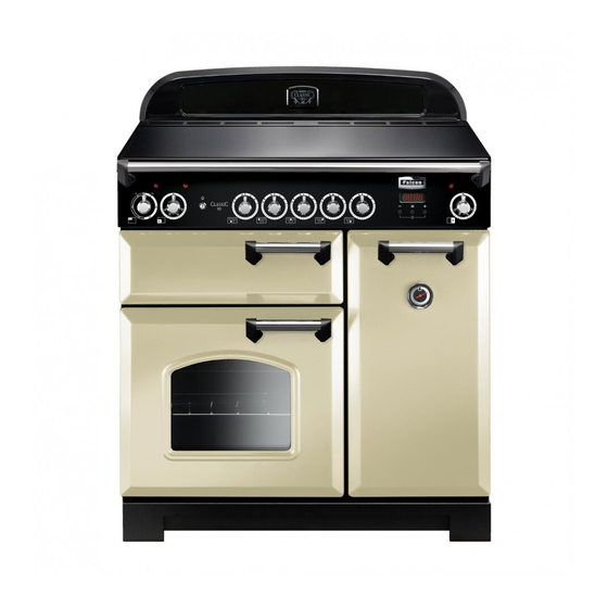
Page 6: Cooker Overview
2. Cooker Overview Fig.2-1 The 90 induction cooker (Fig.2-1) has the following features: Fig.2-2 5 induction cooking zones A control panel A separate grill Main programmable fan oven Tall fan oven ArtNo.312-0004 Correct pans ceramic The Hob Use only pans that are suitable for induction hobs. We recommend stainless steel, enamelled steel pans or cast iron pans with enamelled bases. - Page 7 Make sure that the base of the pan is clean and dry to prevent Fig.2-4 any residue burning onto the hob panel. This also helps 2.3kW 2.3kW 2.3kW prevent scratches and deposits. Always use pans that are the same size as (or slightly larger than) the areas marked on the hob.
- Page 8 heat up at 100% power for a specified time before the power Automatic heat-up time is reduced to the level selected. Power Level at 100% (min:sec) When the Automatic Heat-up function is activated, the hob 0:48 control display will flash alternately between the [A] setting 2:24 and the chosen power level.
-
Page 9: The Grill / Glide-Out Grill
The Grill / Glide-out Grill Fig.2-7 Open the door and pull the grill pan (Fig.2-7) or carriage (Fig.2-8) forward using the handle. The grill has two elements that allow either the whole area of the pan to be heated or just the right-hand half. ArtNo.330-0003 - Grill pan w handle pulled forwards Adjust the heat to suit by turning the knob. -
Page 10: The Clock
The Clock Fig.2-12 ArtNo.300-0004 2-button clock annotated You can use the clock to turn the left-hand oven on and off. The clock must be set to the time of day before the oven will work. Note: When using the timer functions, first set the clock as required before setting the oven temperature and selecting the oven function (multi-function ovens only). - Page 11 Turn the Timer knob to the ( ) position. The display will ArtNo.301-0008 2BC Fig.2-19 show the current time of day plus the ‘cook time’ you just set. Stopping the oven 2 Use the Adjusting knob to set the ‘stop time’ required (Fig.2-19).
- Page 12 The 6-button Clock (Classic & Toledo models) Fig.2-25 Setting the time of day The 6-button LCD clock is shown in Fig.2-25. When the clock is first connected the display flashes ( 0.00) and ( alternately. ArtNo.302-0002 - 6BC annotated Press and hold both the [] and [] buttons down (Fig.2-26).
- Page 13 AUTO is showing, you want to reset to manual cooking Fig.2-35 Fig.2-36 To return to manual cooking from any automatic setting, the ‘cook period’ must be cancelled. Press and hold the [] button and then press the [ –] button until the display reads ( 0.00). ArtNo.302-0009 - Activating ArtNo.302-0008 - the key lock 2 Press the [] button to return to manual cooking.
-
Page 14: Accessories
Accessories Fig.2-42 Fig.2-43 Oven Shelves – Left-hand (Main) Oven In addition to the flat shelves (Fig.2-40), some models are supplied with a drop shelf (Fig.2-41). The drop shelf increases the possibilities for oven shelf spacing. The oven shelves can be easily removed and refitted. ArtNo.320-0012 Removing the shelf 2 ArtNo.320-0011 Removing the shelf 1 Pull the shelf forward until the back of the shelf is stopped by... -
Page 15: Cooking Tips
DocNo.030-0009 - Cooking tips - 90 induction generic 3. Cooking Tips Using your Induction Cooker General Oven Tips If you have not used an induction cooker before please be The wire shelves should always be pushed firmly to the back aware of the following: of the oven. -
Page 16: Cooking Table
4. Cooking Table DocNo.031-0004 - Cooking table - electric & fan single cavity The oven control settings and cooking times given in the table below are intended to be used AS A GUIDE ONLY. Individual tastes may require the temperature to be altered to provide a preferred result. -
Page 17: Cleaning Your Cooker
ArtNo.040-0002 - Cleaning - 90 induction GENERIC 5. Cleaning Your Cooker Isolate the electricity supply before carrying out any major Fig.5-1 cleaning. Allow the cooker to cool. Never use paint solvents, washing soda, caustic cleaners, biological powders, bleach, chlorine based bleach cleaners, coarse abrasives or salt. -
Page 18: Grills
Grills Fig.5-2 The grill pan and grid should be washed in hot soapy water. After grilling meats or any foods that soil, leave to soak for a few minutes immediately after use. Stubborn particles may be removed from the grid using a nylon brush. Alternatively, the grill pan can be washed in a dishwasher. -
Page 19: Glass Door Panels (Some Models)
Glass Door Panels (some models) Fig.5-7 The oven door front panels can be taken off so that the glass panels can be cleaned. Move the cooker forward to gain access to the sides (see the ‘Moving the Cooker’ section under ‘Installation’). Open the oven door slightly and remove the front panel fixing screws from the door sides, two each side (Fig.5-7). -
Page 20: Cleaning Table
Cleaning Table Cleaners listed are available from supermarkets or electrical retailers as stated. For enamelled surfaces use a cleaner that is approved for use on vitreous enamel. Regular cleaning is recommended. For easier cleaning, wipe up any spillages immediately. Hotplate Part Finish Recommended Cleaning Method... -
Page 21: Troubleshooting
DocNo.050-0001 - Troubleshooting - Induction GENERIC 6. Troubleshooting The cooling fan Interference with and repairs to the hob MUST NOT be carried out by unqualified persons. Do not try The induction hob incorporates a cooling fan. This to repair the hob as this may result in injury and cooling fan is active when either the grill or ovens damage to the hob. - Page 22 Food is cooking too slowly, too quickly, or burning Fig.6-1 Cooking times may differ from your previous oven. Check that you are using the recommended temperatures and shelf positions – see the oven ArtNo.324-0005 Oven light bulb cooking guide. Then adjust the settings according to your own individual tastes.
- Page 23 Locate the bulb cover and unscrew it by turning it anti- Fig.6-3 clockwise - it may be very stiff (Fig.6-2). Taking care to protect your fingers with a glove in case the bulb should shatter, unscrew the old bulb. Screw in the new bulb clockwise and then screw the bulb cover back on.
-
Page 24: Installation
INSTALLATION Check the appliance is electrically safe when you have finished. 7. Installation Service and Spares Firstly, please complete the appliance details below and keep them safe for future reference – this information will enable us to accurately identify the particular appliance and help us to help you. Filling this in now will save time and inconvenience if you later have a problem with the appliance. -
Page 25: Dear Installer
INSTALLATION Check the appliance is electrically safe when you have finished. Dear Installer You will also need the following tools: Electric drill Before you start your installation, please complete the details below, so that, if your customer has a problem relating to Masonry drill bit (only required if fitting the cooker on a stone or concrete floor) your installation, they will be able to contact you easily. -
Page 26: Positioning The Cooker
INSTALLATION Check the appliance is electrically safe when you have finished. Positioning the Cooker Fig.7-1 The diagram (Fig.7-1) shows the minimum recommended distance from the cooker to nearby surfaces as given in AS 5601 / AG 601. 1. Overhead – Measurement A The minimum height of any surface above the cooker is 650 mm above the hotplate. -
Page 27: Moving The Cooker
INSTALLATION Check the appliance is electrically safe when you have finished. Moving the Cooker Fig.7-2 On no account try and move the cooker while it is plugged into the electricity supply. The cooker is very heavy, so take great care. DO NOT use the door handles or control knobs to manoeuvre the cooker. -
Page 28: Electrical Connection
INSTALLATION Check the appliance is electrically safe when you have finished. Electrical Connection This appliance must be installed by a qualified electrician to comply with the relevant regulations (AS/NZS 60335.2.6:2002) and also the local electricity supply company requirements. ArtNo.132-0001 - 1 phase 240Vac 50Hz Ensure that the mains characteristics (voltage, nominal, power, etc.) match the ratings indicated on the data plate affixed to the cooker. -
Page 29: Repositioning The Cooker Following Connection
INSTALLATION Check the appliance is electrically safe when you have finished. Refit the rear cover. Repositioning the Cooker following Connection If you need to move the cooker once it has been connected, make sure it is switched off at the supply switch before gripping under the fascia panel and lifting the front of the ArtNo.132-0002 - 3 phase 240/415Vac 50Hz cooker slightly (Fig.7-5). -
Page 30: (Classic Model Only)
INSTALLATION Check the appliance is electrically safe when you have finished. Fitting the Plinth Fig.7-15 Classic & Professional+ models Loosen the three screws along the front bottom edge of the cooker. Hook the central keyhole over the central screw. Twist and fit each end keyhole over their respective screws. -
Page 31: Servicing
WARNING – SERVICING TO BE CARRIED OUT ONLY BY AN AUTHORISED PERSON Disconnect from electricity before servicing. Check appliance is safe when you have finished. 8. Servicing Disconnect the cooker from the electricity supply Fig.8-1 before servicing, particularly before removing any of the following: control panel, side panels, ceramic hob, or any of the electrical components or cover boxes. - Page 32 WARNING – SERVICING TO BE CARRIED OUT ONLY BY AN AUTHORISED PERSON Disconnect from electricity before servicing. Check appliance is safe when you have finished. To Replace a Hob Element Fig.8-3 Disconnect from electricity supply. Lift up the ceramic hob (see 2). The Induction Heating Elements (IHE) are now accessible.
- Page 33 WARNING – SERVICING TO BE CARRIED OUT ONLY BY AN AUTHORISED PERSON Disconnect from electricity before servicing. Check appliance is safe when you have finished. If it is not possible to disconnect the leads in this way, pull the Fig.8-4 Fig.8-5 cooker forward to gain access to the rear.
- Page 34 WARNING – SERVICING TO BE CARRIED OUT ONLY BY AN AUTHORISED PERSON Disconnect from electricity before servicing. Check appliance is safe when you have finished. 14. To Adjust the Main Oven Door Catch Keep Fig.8-11 Open the oven door, and slacken off the locknut at the base of the keep (Fig.8-10).
- Page 35 WARNING – SERVICING TO BE CARRIED OUT ONLY BY AN AUTHORISED PERSON Disconnect from electricity before servicing. Check appliance is safe when you have finished. 19. To Remove an Oven Element Thermal Cut-out Fig.8-12 Disconnect from electricity supply. Pull the cooker forward to gain access to the cover box. Undo the cover screws and lift clear.
-
Page 36: Circuit Diagrams
9. Circuit Diagrams ArtNo.095-0003 - Circuit diagram - 90 induction Circuit Diagram: Hob 2.3kW 2.3kW 2.3kW 1.4kW 1.4kW ArtNo.080-0051 - 90 Elan induction (hob) circuit diagram Code Description Colour Code Touchlite panel Blue Distribution board Brown Left-hand front control Black Left-hand rear control... -
Page 37: Circuit Diagram: Fan Oven
Circuit Diagram: Fan Oven Multi-pin plug P033458 P095199 P033458 ArtNo.080-0064 90 induction (oven) circuit diagram The connections shown in the circuit diagram are for single-phase. The ratings are for 240 V 50 Hz. Code Description Code Description Colour Code Grill energy regulator Right-hand oven element... -
Page 38: Technical Data
10. Technical Data INSTALLER: Please leave these instructions with the user. DATA BADGE LOCATION: Cooker back, serial number repeater badge below oven door opening. Connections Electric 230-240 V 50 Hz Dimensions Overall height minimum 905 mm maximum 930 mm Overall width 900 mm Overall depth 602 mm (to fascia inc. - Page 40 DocNo.000-0002 - Back cover Mercury Clarence Street, Royal Leamington Spa, Warwickshire, CV31 2AD, England. Tel: +44 (0) 1926 457000 Fax: +44 (0) 1926 450526 E-mail: consumers@falconappliances.co.uk ArtNo.000-0003 CE logo...
Need help?
Do you have a question about the 90 Induction and is the answer not in the manual?
Questions and answers