Falcon Classic User's Manual & Installation Instructions
110 dual fuel
Hide thumbs
Also See for Classic:
- User's manual & installation instructions (48 pages) ,
- User manual (44 pages) ,
- User's manual & installation instructions (40 pages)

Related Manuals for Falcon Classic


Summary of Contents for Falcon Classic
- Page 1 USER GUIDE & INSTALLATION INSTRUCTIONS Classic / Professional+ 110 Dual Fuel Australia U110922-02...
-
Page 3: Table Of Contents
Contents Before You Start... Troubleshooting Personal Safety Installation Electrical Connection Safety Service and Spares If You Smell Gas Safety Requirements and Regulations Peculiar Smells Provision of Ventilation Ventilation Location of Cooker Maintenance Conversion Oven Care Positioning the Cooker Grill/Glide-out Grill™ Care Moving the Cooker Cooling Fan Levelling... -
Page 5: Before You Start
Before You Start... • DO NOT use a steam cleaner on your cooker. Your cooker should give you many years of trouble-free cooking if installed and operated correctly. It is important • Always keep combustible materials, e.g. curtains, and that you read this section before you start. flammable liquids a safe distance away from the cooker. -
Page 6: If You Smell Gas
If You Smell Gas Maintenance • DO NOT turn electric switches on or off • Only a qualified service engineer should service the appliance and only approved spare parts should be • DO NOT smoke used. It is recommended that this appliance is serviced annually. -
Page 7: Oven Care
• DO NOT use water on grease fires and never pick up Fig. 1.1 a flaming pan. Turn the controls off and then smother a flaming pan on a surface unit by covering the pan completely with a well fitting lid or baking tray. If available, use a multi-purpose dry chemical or foam- type fire extinguisher. -
Page 8: Grill/Glide-Out Grill™ Care
Grill/Glide-out Grill™ Care Cleaning • When using the grill, make sure that the grill pan is • Isolate the electricity supply before carrying out any in position and pushed fully in, otherwise the control thorough cleaning. Allow the cooker to cool. knobs may become very hot. -
Page 9: Cooker Overview
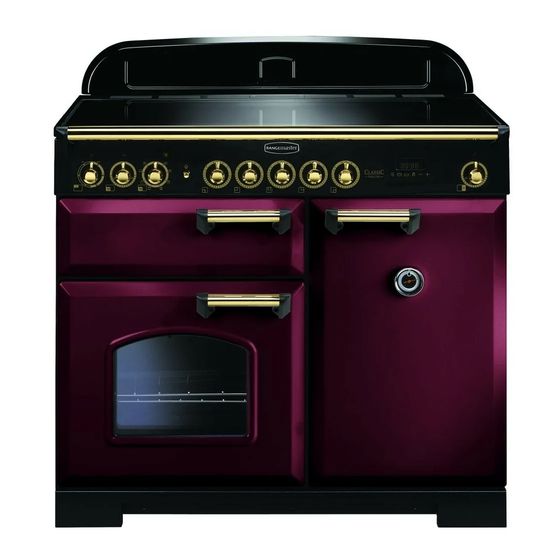
Cooker Overview DocNo.020-0013 - Overview - 110DF - Classic, RM & Toledo lidded Fig. 2.1 The 110 dual fuel cooker (Fig. 2.1) has the following features: Fig. 2.2 6 hotplate burners including a wok burner A control panel A glide-out grill... -
Page 10: Wok Burner
The igniter should spark and light the gas. Keep holding the Fig. 2.3 knob pressed in to let the gas through to the burner for about ten seconds. If, when you let go of the control knob, the burner goes out, then the FSD has not been bypassed. -
Page 11: The Wok Cradle (Optional Extra)
The Wok Cradle (optional extra) Fig. 2.9 The wok cradle is designed to fit a 35 cm wok. If you use a different wok, make sure that it fits the cradle. Woks vary very widely in size and shape. It is important that the wok sits down on the pan support –... -
Page 12: The Grill
To heat the right-hand half, turn the control knob counter- clockwise. The neon indicator light by the grill control will come on. ArtNo.235-0007 - Classic DL grill control For best results, slide the grill pan back into the grill chamber and preheat the appropriate part(s) of the grill for two minutes. -
Page 13: The Ovens
Main Oven Lights Press the button to turn the lights on (Fig. 2.22). ArtNo.235-0004 - Classic DL oven 1 If an oven light fails, turn off the power supply before changing the bulb. See the ‘Troubleshooting’ section for details on how to change the bulb. -
Page 14: Accessories
Accessories Fig. 2.23 Shelf guard Oven Shelves The oven shelves (Fig. 2.23) can be easily removed and refitted. Pull the shelf forward until the back of the shelf is stopped by the shelf stop bumps in the oven sides (Fig. 2.24). Front Lift up the front of the shelf so the back of the shelf will pass under the shelf stop and then pull the shelf forward... -
Page 15: Glide-Out Oven Shelf (Optional)
Glide-out Oven Shelf (optional) Fig. 2.30 A glide-out oven shelf is available for either oven (Fig. 2.30). Note: The Handyrack must be removed before fitting the glide-out shelf. The rungs on the shelf supports are in pairs. The glide-out shelf runners can be fitted to any pair except the top. To fit the glide-out shelf runners FRONT Hook the rear of the runner over the top rung of a pair of shelf... -
Page 16: Button - Rotary Clock
3. 2 Button - rotary clock The clock must be set to the time of day before the oven Fig. 3.1 ArtNo.300-0005 2BC will work. minute minder setting Setting the Clock Once the cooker is connected and switched on, the display will start to flash. - Page 17 To stop the oven at a specific time of day Fig. 3.5 You have set the required temperature and function mode and you would like the oven to automatically stop. TOP TIP Make a note of the current time so you do not forget. Turn the Timer (A) knob to the Stop Time (G) setting.
- Page 18 To start and stop the oven automatically Fig. 3.9 The timer allows you to automatically start and stop by a combination of the length of the cooking time and the stop time. Giving you the flexibility to cook casseroles etc while you are out.
-
Page 19: Button Clock
3 Button clock Using the clock Fig. 4.1 You can use the clock to turn the programmable oven on and off. The clock must be set to the time of day before the oven will work. NOTE: When using the timer functions, first set the clock as ArtNo.306-0001 - 3-button clock required before setting the oven temperature. - Page 20 When the ‘stop time’ is reached an alarm will sound and Fig. 4.7 the oven will stop working. The word ‘AUTO’ will flash on the display (Fig. 4.6). Press any button to stop the alarm and return to manual cooking. If the alarm is not stopped, it will stop ArtNo.306-0001 - 3-button clock automatically after 7 minutes.
-
Page 21: Cooking Tips
Cooking Tips Tips on cooking with the timer General oven tips If you want to cook more than one dish, choose dishes that The wire shelves should always be pushed firmly to the back require approximately the same cooking time. However, of the oven. -
Page 22: Cooking Table
Cooking Table The oven control settings and cooking times given in the table below are intended to be used as a Top (T) guide only. Individual tastes may require the temperature to be altered to provide a preferred result. ArtNo.050-0007 Centre (C) Oven shelf positions Food is cooked at lower temperature in a fan oven than in a conventional oven. -
Page 23: Cleaning Your Cooker
Cleaning your cooker Essential information Fig. 7.1 Isolate the electricity supply before carrying out any thorough cleaning. Allow the cooker to cool. NEVER use paint solvents, washing soda, caustic cleaners, biological powders, bleach, chlorine based bleach cleaners, coarse abrasives or salt. DO NOT mix different cleaning products –... -
Page 24: The Griddle
The Griddle Fig. 7.5 ArtNo.331-0003 Grill frame out, no pan Always clean the griddle after use. Allow it to cool completely before removing. Immerse the griddle plate in hot soapy water. Use a soft cloth or, for stubborn stains, a nylon washing up brush. -
Page 25: Ovens
Glass fronted door panels Fig. 7.8 The oven door front panels can be taken off so that the glass panels can be cleaned. Move the cooker forward to gain access to the sides (see the ‘Moving the Cooker’ section under ‘Installation’). -
Page 26: Cleaning Table
Cleaning table Cleaners listed are available from supermarkets or electrical retailers as stated. For enamelled surfaces use a cleaner that is approved for use on vitreous enamel. Regular cleaning is recommended. For easier cleaning, wipe up any spillages immediately. Hotplate Part Finish Recommended Cleaning Method... -
Page 27: Troubleshooting
Troubleshooting Hotplate/Cooktop ignition or hotplate burners faulty Food is cooking too slowly, too quickly, or burning Is the power on? Is the clock illuminated? Cooking times may differ from your previous oven. If not, there maybe something wrong with the power supply. Check that you are using the recommended temperatures and shelf positions –... - Page 28 Oven light is not working Fig. 8.1 The bulb has probably burnt out. You can buy a replacement bulb (which is not covered under the warranty) from a good electrical shop. Ask for a 40 W – 230 V halogen lamp (G9) (Fig. 8.1). Turn off the power at the circuit breaker.
-
Page 29: Installation
Please Note For warranty information and how to request a remedy, please refer to the Warranty Statement at www.andico.com.au/customer-care/falcon or contact Customer Care. Out of Warranty We recommend that our appliances are serviced regularly throughout their life to maintain the best performance and efficiency. -
Page 30: Safety Requirements And Regulations
INSTALLATION Check the appliance is electrically safe and gas sound when you have finished. Safety Requirements and Regulations Provision of Ventilation Please read the Before you start... chapter, before This appliance is not connected to a combustion products you begin any installation and maintenance work on evacuation device. - Page 31 12. Screws for fitting the restraining chain and bracket Roasting tin Plinth (2-piece model shown) ArtNo.324-0004 Roasting tin Handles Stability location bracket ArtNo.210-0014 - Classic handles Stability bracket Restraining chain & hook ArtNo.020-0021 - Restraining chain & hook Conduit box...
-
Page 32: Positioning The Cooker
70°C. If this appliance is installed near vinyl wrapped surfaces, use an installation kit available from the vinyl-wrap supplier. Falcon cannot accept any responsibility for damage caused due to installation into cabinets with low temperature tolerances. -
Page 33: Moving The Cooker
INSTALLATION Check the appliance is electrically safe and gas sound when you have finished. Moving the Cooker Fig. 9.3 On no account try and move the cooker while it is plugged into the electricity supply. The cooker is very heavy, so take great care. We recommend that two people manoeuvre the cooker. -
Page 34: Levelling
INSTALLATION Check the appliance is electrically safe and gas sound when you have finished. Levelling Fig. 9.6 You are recommended to use a spirit level on a shelf in one of the ovens to check for level. Place the cooker in its intended position taking care not to twist it within the gap between the kitchen units as damage may occur to the cooker or the units. -
Page 35: Gas Connection
INSTALLATION Check the appliance is electrically safe and gas sound when you have finished. Gas Connection Fig. 9.10 Must be in accordance with the relevant standards. Pipework Pipework The gas supply needs to terminate with a side-facing threaded fitting ½” connection (Fig. 9.10). The inlet connector is located just below the hotplate level at the rear of the cooker. - Page 36 INSTALLATION Check the appliance is electrically safe and gas sound when you have finished. Electrical Connection Fig. 9.12 This appliance must be installed by a qualified electrician to comply with with current AS/NZS 3000 Wiring Rules and regulations in force. Make sure that the mains characteristics (voltage, nominal, power, etc.) match the ratings indicated on the cooker data plate.
- Page 37 INSTALLATION Check the appliance is electrically safe and gas sound when you have finished. Fixed Wiring Fig. 9.14 Disconnect from the mains supply. For connection to fixed wiring, i.e. flexible conduit, remove the electrical terminal cover box on the back panel (Fig.
-
Page 38: Final Fitting
INSTALLATION Check the appliance is electrically safe and gas sound when you have finished. Final Checks Fig. 9.18 Note: The clock must be set before the ovens will work. See ‘The Clock’ section for instructions on setting the time of day. Hotplate Check Check each burner in turn. -
Page 39: Conversion To Lp Gas
WARNING – SERVICING TO BE CARRIED OUT ONLY BY AN AUTHORISED PERSON Disconnect from electricity and gas before servicing. Check appliance is safe when you have finished. Conversion to LP Gas Conversion from Natural Gas (1.0 kPa) Fig. 10.1 to LPG X Propane (2.54 kPa) A suitably competent person must perform the conversion. -
Page 40: Set The Governor
WARNING – SERVICING TO BE CARRIED OUT ONLY BY AN AUTHORISED PERSON Disconnect from electricity and gas before servicing. Check appliance is safe when you have finished. Set the Governor Fig. 10.4 Unscrew the governor’s brass top. In the base of the brass top is a plastic snap-in converter device (Fig. -
Page 41: Servicing
1.1 To Remove the Control Panel ArtNo.270-0019 - Proplus tags 1 DISCONNECT FROM THE ELECTRICITY SUPPLY. Classic – Removing the Control Panel Remove the handrail. Now remove the 2 cross-headed screws hidden behind the handrail end brackets (Fig. 11.1). Pull off all the control knobs and remove the fixing screws underneath the control panel. -
Page 42: Hotplate
WARNING – SERVICING TO BE CARRIED OUT ONLY BY AN AUTHORISED PERSON Disconnect from electricity before servicing. Check appliance is safe when you have finished. 2 Hotplate Fig. 11.3 BEFORE SERVICING ANY GAS CARRYING COMPONENTS, TURN OFF THE GAS SUPPLY. 2.1 To Remove the Hotplate Pull the cooker forward to gain access to the rear. -
Page 43: Controls
WARNING – SERVICING TO BE CARRIED OUT ONLY BY AN AUTHORISED PERSON Disconnect from electricity before servicing. Check appliance is safe when you have finished. 2.4 To Replace a Hotplate Burner Electrode Replace the control panel in the reverse order and test for correct operation. -
Page 44: Ovens
WARNING – SERVICING TO BE CARRIED OUT ONLY BY AN AUTHORISED PERSON Disconnect from electricity before servicing. Check appliance is safe when you have finished. 5 Ovens Fig. 11.5 5.1 To Replace an Oven Thermostat DISCONNECT FROM THE ELECTRICITY SUPPLY. Remove the control panel and hotplate (see 1.1 &... -
Page 45: Doors
WARNING – SERVICING TO BE CARRIED OUT ONLY BY AN AUTHORISED PERSON Disconnect from electricity before servicing. Check appliance is safe when you have finished. 5.5 To Remove an Oven Element Fig. 11.6 DISCONNECT FROM THE ELECTRICITY SUPPLY. Remove the oven inner back (see 5.2). Element fixing screws Remove the 2 screws from the top of the element and the 1 from the bottom of the element (Fig. - Page 46 WARNING – SERVICING TO BE CARRIED OUT ONLY BY AN AUTHORISED PERSON Disconnect from electricity before servicing. Check appliance is safe when you have finished. 6.4 To Replace an Oven Door Outer Panel Fig. 11.11 Move the cooker forwards to gain access to the sides. Open the oven door slightly and remove the 4 front panel fixing screws from the door sides (2 each side), (Fig.
-
Page 47: Circuit Diagram
12. Circuit Diagram P095199 P095199 P095199 Classic, Kitchener & Professional+ 110 DF The connections shown in the circuit diagram are for single-phase. The ratings are for 230 V 50 Hz. Code Description Code Description Code Colour Grill front switch Oven light switch Blue The connections shown in the circuit diagram are for single-phase. -
Page 48: Technical Data
13. Technical Data This cooker is designed for use on Natural Gas, although a conversion for LP (LPG X Propane (2.54 kPa)) gas is packed with the cooker. INSTALLER: Please leave these instructions with the user. DATA BADGE LOCATION: Cooker back, serial number repeater badge below oven door opening. Country of destination: Australia. - Page 49 NOTE...
- Page 50 NOTE...
- Page 51 NOTE...
- Page 56 Clarence Street, Royal Leamington Spa, Warwickshire, CV31 2AD, England. Tel: +44 (0) 1926 457628 E-mail: consumers@falconappliances.co.uk...
Need help?
Do you have a question about the Classic and is the answer not in the manual?
Questions and answers