Table of Contents
Advertisement
AUTOMATIC TECHNOLOGY AUSTRALIA PTY LTD
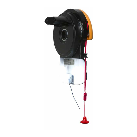
GDO-6 v2 Slim-Drive EasyRoller
®
ROLL UP GARAGE DOOR OPENER
WARNING
OWNERS COPY
It is vital for the safety of persons to follow all
instructions. Failure to comply with the installation
instructions and the safety warnings may result in
serious personal injury and/or property and remote
Installation Instructions
control opener damage.
Please save these instructions for future reference.
Advertisement
Table of Contents

Related Manuals for Automatic Technology GDO-6 v2 Slim-Drive EasyRoller


Summary of Contents for Automatic Technology GDO-6 v2 Slim-Drive EasyRoller
-
Page 1: Installation Instructions
AUTOMATIC TECHNOLOGY AUSTRALIA PTY LTD GDO-6 v2 Slim-Drive EasyRoller ® ROLL UP GARAGE DOOR OPENER WARNING OWNERS COPY It is vital for the safety of persons to follow all instructions. Failure to comply with the installation instructions and the safety warnings may result in... -
Page 2: Declaration Of Incorporation
Maximum Door Size: 2700mm Height X 5500mm Width. Maximum Door Weight: 90Kg. This declaration is made by Peter Matthews General Manager Automatic Technology Australia Pty. Ltd. 17-19 Advantage Road, Highett, Australia Tel: +61 3 9532 2788 Installers Name Signature... -
Page 3: Table Of Contents
Automatic Technology Australia Pty Ltd to the extent that such may be lawfully excluded hereby expressly disclaims all conditions or warranties, statutory or otherwise which may be implied by laws as conditions or warranties of purchase of an Automatic Technology Australia Pty Ltd Roll Up Garage Door Opener. -
Page 4: Safety Warnings
IMPORTANT SAFETY INSTRUCTIONS Warning - It is vital for the safety of persons to follow all instructions. Failure to comply with the following Safety Rules may result in serious personal injury and/or property damage. ADDITIONAL SAFETY protection The unit should be installed so that it is protected from STRONGLY recommend the fitting of a Photo Electric the elements. -
Page 5: Product Features
FEATURES Thank you for purchasing the Slim- ISS (INTELLIGENT SAFETY VACATION MODE Drive EasyRoller Automatic Garage OBSTRUCTION SYSTEM) A transmitter can be programmed to ® Door Opener. This opener is designed to Whilst performing a close cycle the block out all other transmitters that have suit vertical operating continuous door will automatically reverse if it been programmed into the opener’s... -
Page 6: Operating Controls
OPERATING CONTROLS P. E. SHUNT. The shunt has to be CLOSE drive button (red) is used O/S/C button (Yellow) is used removed when connecting a Photo only during installation to help set after set up to test the Open, Stop Electric Beam. - Page 7 OPERATING CONTROLS P.E. SHUNT, PE INPUT, OSC INPUT, ENGAGE/DISENGAGEMENT HANDLE LIGHT INPUT, 24V DC OUTPUT INC. EASY ACCESS TRANSMITTER LIGHT CODE BUTTON (BLACK) SET BUTTON (ORANGE) CODING LED (RED) O/S/C BUTTON (YELLOW) DOOR CODE BUTTON (BLUE) FUSE DOOR STATUS LED (YELLOW) BATTERY CHARGER INPUT CLOSE DRIVE BUTTON (RED) OPEN DRIVE BUTTON (GREEN)
-
Page 8: Package Contents
PACKAGE CONTENTS ITEM QUANTITY GDO-6 SLIM-DRIVE EASYROLLER DRIVE UNIT ® EASY ACCESS TRANSMITTER EAT-1 (NOT INCLUDED IN SOME MODELS) KEY RING TRANSMITTER PTX-4 PTX-4 WALL MOUNT BRACKET ALKALINE BATTERY A23 12V WEIGHT BAR (NOT INCLUDED IN SOME MODELS) PAN HEAD SCREW M4x50mm (NOT INCLUDED IN SOME MODELS) NILOCK HEX NUT M4 (NOT INCLUDED IN SOME MODELS) FLAT WASHER I.D 3/16 x 1/2 (NOT INCLUDED IN SOME MODELS) SCREW #6x1”... -
Page 9: Side Room Requirements
BEFORE INSTALLATION IMPORTANT SAFETY INSTRUCTIONS FOR FIG. 1 INSTALLATION Warning: Incorrect installation can lead to severe injury. Follow ALL installation instructions. SIDE ROOM REQUIREMENTS Fig. 1 shows the minimum and recommended side room that is required to mount the opener. The distance between the edge of the door curtain and the inside of the bracket must be at least 40mm. -
Page 10: Easy Access Transmitter
EASY ACCESS TRANSMITTER 4. EASY ACCESS TRANSMITTER FIG. 4 The Easy Access Transmitter is prepared ready for use with the battery pre-installed. Before the transmitter can be operational, the transmitter code has to be stored into the openers memory. To store the code refer to Step 10.1 on page 15. REMOVING THE COVER TO REPLACE BATTERY 1. -
Page 11: Mounting The Opener
MOUNTING THE OPENER 5. FIXING DRIVE UNIT TO THE DOOR FIG. 8 The EasyRoller Drive Assembly can be fixed to the roll up garage door in a variety of ways. Described below is one method of fixing. Make sure there is enough side room to slide the drive assembly onto shaft. -
Page 12: Fixing Curtain To Drum
SETTING LIMITS 6. FIXING DOOR CURTAIN TO DRUM FIG. 11 WHEEL The door curtain has to be secured to the drum wheel with suitable fasteners. 1. With the door in the fully closed position, mark the curtain (Fig. 11) on both ends of the door. 2. -
Page 13: Setting Limits Via Transmitter
SETTING LIMITS 8. SETTING DOOR TRAVEL LIMIT FIG. 14 POSITIONS VIA THE REMOTE CONTROL IMPORTANT NOTE: The O/S/C button will not function until the open and close limits position are set. NOTE: The opener is factory preset for installation on the RIGHT HAND SIDE. -
Page 14: Setting Obstruction Force Margin (Iss)
SETTING SAFETY OBSTRUCTION FORCE 9. SAFETY OBSTRUCTION TEST FIG. 16 Please take care when testing the Safety Obstruction Force. Due to Excessive forces failure to follow this warning may cause SERIOUS PERSONAL INJURY and/or property damage. The test below should be repeated at regular intervals (approximately every two months). -
Page 15: Coding Transmitters
CODING TRANSMITTERS 10. SETTING TRANSMITTERS CODES FIG. 18 The memory in the opener can store up to 24 remote control transmitters. Make sure to insert the battery into the transmitter with the correct polarity. NOTE: Remove the control panel cover for access. Remember to replace the cover when set up is complete. -
Page 16: Deleting Transmitters
CODING TRANSMITTERS 11. STORING TRANSMITTER(S) FROM A FIG. 20 REMOTE LOCATION Using this method you don’t need to have access to the control panel on the Door Opener. However, you do need a transmitter that is pre coded to the controller’s receiver. IMPORTANT NOTE: The Door or Courtesy Light must be activated when the step below is performed. -
Page 17: Connecting Photo Electric Beam
PE BEAM AND AUTO CLOSE 13. FITTING THE SAFETY PHOTO FIG. 22 ELECTRIC BEAM SENSOR (OPTIONAL) Locate the Photo Electric Beam (P.E.) (normally closed contact REMOVE type) in a strategic location within doorway. We recommend PE SHUNT 150mm above the floor level and as close as possible to the door opening, inside the garage. -
Page 18: 16. Setting Courtesy Light Time
FINAL SET UP NOTE: Remove the control panel cover for access. FIG. 25 Remember to replace the cover when set up is complete. 16. SETTING COURTESY LIGHT TIME The preset courtesy light time on the door opener is 3 minutes. This time can be changed by the following: 1. -
Page 19: Door Status Indicators
PARAMETERS DOOR STATUS INDICATORS OPEN LED CLOSE LED DOOR STATUS DOOR OPENER STATE BEEPER GREEN LED YELLOW OPEN CLOSE FLASHING OPENING FLASHING CLOSING DOOR TRAVEL STOPPED FLASHING FLASHING DOOR OBSTRUCTED WHEN OPENING FLASHING BEEPS WHILE DOOR OBSTRUCTED WHEN CLOSING FLASHING DOOR IS MOVING ALTERNATING ALTERNATING... -
Page 20: Factory Default Settings
DEFAULT SETTINGS AND SPECIFICATIONS FACTORY DEFAULT SETTINGS DEFAULT STEP MAXIMUM MAXIMUM MOTOR RUN TIME 25 Secs. — — COURTESY LIGHT TIME 3 Mins. 10 Secs. 4 Mins. OBSTRUCTION FORCE MARGIN AUTO CLOSE TIME 0 Secs. 1 Sec. 4 Mins. TECHNICAL SPECIFICATIONS INPUT VOLTAGE: 230V - 240V AC 50Hz CONTROLLER VOLTAGE:... -
Page 21: Trouble Shooting Guide
TROUBLE SHOOTING SYMPTOM POSSIBLE CAUSE REMEDY Switch on mains power. Door will not operate. Mains power not switched on. Remove obstruction. Door is obstructed. Unlock door or remove jam. Door is locked or motor jammed. Door requires service/repair by qualified Door tracks/hardware damaged. -
Page 22: Parts List
SPARE PARTS LIST WHEN ORDERING SPARE PARTS PLEASE QUOTE THE ORDER CODE NUMBER TO YOUR INSTALLER/DEALER. -
Page 23: Warranty
Trade Practices Act 1974 (Cth). (Trade Practices Act applicable to Australia only). 2. Subject to all of the matters set out below, Automatic Technology Australia Pty Ltd ("ATA") warrants: (a) swing and sliding gate opener drive units for twelve (12) months or 2500 cycles, whichever occurs first;... -
Page 24: Supplier/Installer Information
Orion House 14 Barn Hill Stamford Lincolnshire PE9 2AE United Kingdom Tel: +44 (0) 1780 758 528 Fax: +44 (0) 1780 758 501 ©February 2006 Automatic Technology Australia Pty Ltd. All Rights Reserved. SecuraCode and EasyRoller are registered trademarks of Automatic Technology ®...
Need help?
Do you have a question about the GDO-6 v2 Slim-Drive EasyRoller and is the answer not in the manual?
Questions and answers
Where can i buy the easy access transmitter for a GDO-6 V2 Slim-drive door opener?