Superior DRL4543TEN Installation And Operation Instructions Manual
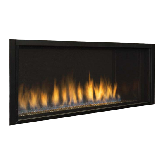
Direct-vent linear gas fireplace
Hide thumbs
Also See for DRL4543TEN:
- Installation and operation instructions manual (40 pages) ,
- Installation and operation instructions manual (48 pages) ,
- Quick start manual (2 pages)
Table of Contents
Advertisement
P/N 126718-01 Rev. A 1/2014
.
P126718-01
INSTALLER: Leave this manual with the appliance.
CONSUMER: Retain this manual for future reference.
A barrier designed to reduce the risk of burns
from the hot viewing glass is provided with this
appliance and shall be installed.
This appliance may be installed in an aftermarket permanently located, manufactured home (USA only) or mobile
home, where not prohibited by local codes. This appliance is only for use with the type of gas indicated on the
rating plate. This appliance is not convertible for use with other gases, unless a certified kit is used.
WARNING AVERTISSEMENT AVISO
HOT GLASS WILL
CAUSE BURNS.
DO NOT TOUCH GLASS
UNTIL COOLED.
NEVER ALLOW CHILDREN
TO TOUCH GLASS.
WARNING: If the information in these
instructions is not followed exactly, a fire or
explosion may result causing property damage,
personal injury or death.
— Do not store or use gasoline or other
flammable vapors and liquids in the vicinity
of this or any other appliance.
— WHAT TO DO IF YOU SMELL GAS:
• Do not try to light any appliance.
• Do not touch any electrical switch; do not
use any phone in your building.
• Immediately call your gas supplier from
a neighbor's phone. Follow the gas
supplier's instructions.
• If you cannot reach your gas supplier, call
the fire department.
— Installation and service must be performed
by a qualified installer, service agency or the
gas supplier.
Installation and Operation Instructions
Superior
Models
PFS
®
C
US
Installateur : Laissez cette notice avec l'appareil.
Consommateur : Conservez cette notice pour consultation ultérieure.
Une barrière conçue pour réduire le risque de brûlure
par le hublot chaude est fournie avec l'appareil et doit
être installé.
UNE SURFACE VITRÉE CHAUDE PEUT
CAUSER DES BRÛLURES.
LAISSER REFROIDIR LA SURFACE VITRÉE
AVANT D'Y TOUCHER.
NE PERMETTEZ JAMAIS À UN ENFANT DE
TOUCHER LA SURFACE VITRÉE.
AVERTISSEMENT : Assurez-vous de bien suivre les
instructions données dans cette notice pour réduire au
minimum le risque d'incindie ou d'explosion ou pour éviter
tout dommage matériel, toute blessure ou la mort.
— Ne pas entreposer ni utilizer d'essence ni d'autres
vapeurs ou liquides inflammables dans le voisinage
de cet appareil ou de tout autre appareil.
— QUE FAIRE SI VOUS SENTEZ UNE ODEUR DE GAZ :
• Ne pas tenter d'allumer d'appareil.
• Ne touchez à aucan interrupteur. Ne pas vous
servir des téléphones se trouvant dans le bâtiment
où vous trouvez.
• Appelez immédiatement votre fournisseur de
gaz depuis un voisin. Suivez les instructions du
fournisseur.
• Si vous ne pouvez rejoindre le fournisseur de gaz,
appelez le service des incindies.
— L'installation et l'entretien doivent être assurés par un
installateur ou un service d'entretien qualifié ou par le
fournisseur de gaz.
Direct-Vent Linear Gas Fireplace
TM
DRL4543TEN
DRL4543TEP
EL VIDRIO CALIENTE
CAUSARÁ QUEMADURAS.
USTED DEBE NUNCA TOCAR
EL VIDRIO CALIENTE.
LOS NIÑOS DEBEN NUNCA
TOCAR EL VIDRIO.
Advertisement
Table of Contents

Subscribe to Our Youtube Channel
Related Manuals for Superior DRL4543TEN


Summary of Contents for Superior DRL4543TEN
- Page 1 Installation and Operation Instructions Superior Direct-Vent Linear Gas Fireplace P/N 126718-01 Rev. A 1/2014 Models DRL4543TEN DRL4543TEP ® P126718-01 INSTALLER: Leave this manual with the appliance. Installateur : Laissez cette notice avec l’appareil. CONSUMER: Retain this manual for future reference.
-
Page 2: Table Of Contents
TABLE OF CONTENTS Safety ..............2 Replacing Light Bulbs ........29 Local Codes............4 Gas Control Module System......30 Product Identification ........... 5 Remote Control Operation......... 30 Product Features ..........5 Specifications ............ 33 Requirements for the Commonwealth of Replacement Parts ..........33 Massachusetts............. - Page 3 SAFETY Continued This vented gas fireplace is a sealed combus- WARNING: Do not use a tion gas fireplace designed for residential ap- plications. This fireplace must be installed with blower insert, heat exchanger INNOVATIVE HEARTH PRODUCTS vent pipe insert or other accessory not ap- components and terminations.
-
Page 4: Local Codes
SAFETY Continued 6. Have venting system inspected annually Keep the area around your by a qualified service person. If needed, fireplace clear of combustible have venting system cleaned or repaired. materials, gasoline and other See Cleaning and Maintenance, page 28. flammable vapor or liquids. -
Page 5: Product Identification
PRODUCT IDENTIFICATION Spacers Glass Door Flue Collar Nailing Flange Pebble Pan Access Door Figure 1 - Direct Vent Linear Fireplace PRODUCT FEATURES These are a few facts that can help you un- • Each time you turn on your fireplace, you derstand and enjoy your direct vent fireplace: may notice some amount of condensation on the inside of the fireplace glass. -
Page 6: Requirements For The Commonwealth Of Massachusetts
REQUIREMENTS FOR THE COMMONWEALTH OF MASSACHUSETTS INSPECTION For all side wall horizontally vented gas fueled equipment installed in every dwelling, building or The state or local gas inspector of the side structure used in whole or in part for residential wall horizontally vented gas fueled equipment purposes, including those owned or operated by shall not approve the installation unless, upon... -
Page 7: Pre-Installation
PRE-INSTALLATION LOCATION AND SPACE CLEARANCES REQUIREMENTS Minimum clearances to combustibles for the fireplace are as follows: Determine the safest and most efficient loca- *Back and sides 1" tion for your direct vent fireplace. Make sure that rafters and wall studs are not in the way Perpendicular walls 8"... - Page 8 PRE-INSTALLATION Continued 17.50" Concrete Board 38" 53.25" Figure 4 - Installing Concrete Board Figure 2 - Framing Clearances for One Sided Application Wall 15.25" 38" Mantel Mantel from Ref. Depth Ref. Top of Opening 12" 24" 9" 21" 6" 18" 4"...
- Page 9 PRE-INSTALLATION Continued Figure 6 - Direct Linear Fireplace Series Dimensions www.SuperiorFireplaces.US.com 126718-01A...
-
Page 10: Location Of Termination Cap
LOCATION OF TERMINATION CAP Fixed Openable Fixed Closed Closed Openable TERMINATION CAP GAS METER RESTRICTED AREA AIR SUPPLY INLET (TERMINATION PROHIBITED) A = clearance above grade, veranda, porch, deck, or I = clearance to service regulator vent outlet [*72" (182.9 cm) balcony [*12"... -
Page 11: Venting Installation
VENTING INSTALLATION NOTICE: Read these instruc- NOTICE: Do not seal termination tions completely before attempt- cap to vent pipe. Cap must be removable for vent inspection ing installation. and maintenance. These models are tested and approved for use with an IHP (direct vent) pipe components INSTALLATION PRECAUTIONS and terminations. -
Page 12: Venting Installation
VENTING INSTALLATION Continued INSTALLATION PLANNING etrated is constructed of noncombustible material, such as masonry block or con- There are two basic types of direct vent crete, a 8 " hole with zero clearance is installation: acceptable (see Figure 9). • Horizontal Termination •... - Page 13 VENTING INSTALLATION Continued Carefully move fireplace, with vent as- 5. Noncombustible Exterior Wall: Position sembly attached, toward wall and insert horizontal vent cap in center of the 8 " vent pipe into horizontal termination. Pipe round hole and attach to exterior wall overlap should be a minimum of 1 "...
- Page 14 VENTING INSTALLATION Continued Minimum Siding Pipe Standoff Horizontal Termination Configurations Overlap Direct Figure 14 and 15, page 15, shows the configu- Screws Vent rations for venting with horizontal termination Pipe Wall with a chart of critical minimum and maximum Firestop dimensions which MUST be met.
- Page 15 VENTING INSTALLATION Continued GROUND FLOOR INSTALLATION Recommended Applications: • Through the wall using round or 1' Pipe Min. On 90° Elbow square termination Horizontal Run V + 90· Elbow Wall Firestop Horizontal High Wind Square Termination 53'' Min. (V) Vertical Required (H) Horizontal Plus ¼''...
- Page 16 VENTING INSTALLATION Continued Vertical High Wind Termination Vent Termination Chart Installation Minimum Height Note: Vertical restrictor must be installed in Roof Pitch Feet Min. all vertical installations. Flat to 6/12 1. Determine route your vertical venting 6/12 to 7/12 1.25 will take.
- Page 17 VENTING INSTALLATION Continued Vertical Termination Configurations 2. Assemble desired lengths of pipe and elbows necessary to reach from fireplace Figure 17 and 18, page 17 and 18, shows the flue up through firestop. Be sure all pipe configurations for vertical termination. and elbow connections are fully twist- locked (see Figure 8, page 12).
- Page 18 VENTING INSTALLATION Continued PARTS LIST FOR VENTING KITS Vertical AND COMPONENTS Venting INNOVATIVE HEARTH PRODUCTS (5/8") V = 40' max. Pipe & Vent Kits Number Description P58-6 6" Section Double Wall Pipe, Galvanized P58-12 12" Section Double Wall Pipe, Galvanized P58-24 24"...
-
Page 19: Fireplace Installation
FIREPLACE INSTALLATION CHECK GAS TYPE For propane/LP connection only, the installer Use proper gas type for the fireplace unit you must supply an external regulator. The exter- are installing. If you have conflicting gas types, nal regulator will reduce incoming gas pres- do not install fireplace. - Page 20 FIREPLACE INSTALLATION Continued Check your building codes for any special WARNING: Use pipe joint requirements for locating equipment shutoff valve to fireplaces. sealant that is resistant to liquid Apply pipe joint sealant lightly to male NPT petroleum (LP) gas. threads. This will prevent excess sealant from going into pipe.
- Page 21 FIREPLACE INSTALLATION Continued CHECKING GAS CONNECTIONS 3. Check all joints from propane/LP supply tank or gas meter to equipment shutoff WARNING: Test all gas piping valve (see Figure 24 or Figure 25). Apply noncorrosive leak detection fluid to all and connections, internal and joints.
- Page 22 FIREPLACE INSTALLATION Continued REMOVING/REPLACING GLASS 3. Make sure control knob of fireplace is in the OFF position. DOOR 4. Check all joints from equipment shutoff CAUTION: Do not operate valve to gas valve (see Figure 24 or Figure 25, page 21). Apply noncorrosive this fireplace with a broken glass leak detection fluid to all joints.
- Page 23 FIREPLACE INSTALLATION Continued Replacing Glass Door touches ember material. Do not block air slots by using too much ember material 1. Position door frame in front of firebox in one area. Do not block pilot ports with opening tilting top of door about 45° to- embers.
- Page 24 FIREPLACE INSTALLATION Continued Removing False Door 1. In the rear of the fireplace, remove false door just as you would remove the front glass door. Refer to Removing/Replacing Glass Door, page 22 of this manual for instruction. Discard false door. Removing Rear Interior Wall 1.
- Page 25 FIREPLACE INSTALLATION Continued Side You may chose to drill pilot holes into the Access Filler face using a 1/8" drill bit. Do not use self Door tapping screws, use any #10 x 1/2" screw. 3. In locations of extreme weather, it is rec- ommended to apply a bead of high tem- perature sealant around the edge where the exterior door meets the fireplace face.
-
Page 26: Operation
FIREPLACE INSTALLATION Continued Removing Exterior Glass Door 1. Using a flat head screw driver, pop out Trim the top and bottom trim pieces as shown in Figure 37. 2. Remove 8 screws at top and bottom of glass door and remove glass door. Screws Trim Figure 37 - Removing Exterior Glass... - Page 27 OPERATION Continued TO TURN OFF GAS 10. Turn safety shutoff switch to the ON position. TO APPLIANCE 11. Visually locate pilot. Ignitor should begin 1. Turn off safety shutoff switch. to spark and main burner should ignite 2. Turn off all electric power to appliance if once flame appears at pilot.
-
Page 28: Inspecting Burners
INSPECTING BURNERS If burner flame pattern differs from that de- Check pilot flame pattern and burner flame scribed: patterns often. • turn fireplace off (see To Turn Off Gas to PILOT ASSEMBLY Appliance), page 27 The pilot assembly is factory preset for the •... -
Page 29: Replacing Light Bulbs
CLEANING AND MAINTENANCE Continued PILOT AND BURNERS other airborne particles to cling to the glass surface. During initial start-up a slight film may • Remove material before cleaning burners form on the glass due to paint curing. The and replace when cleaning is complete. glass should be cleaned several times with a •... -
Page 30: Gas Control Module System
GAS CONTROL MODULE SYSTEM The module has 2 special features built into 3. When the remote/off is in the REMOTE the system. position the burner will operate from the Remote Control transmitter. Continuous Pilot Feature This allows the change from a spark to pilot NOTE: The module must be programmed to system to a standing pilot system the Remote Control transmitter. - Page 31 REMOTE CONTROL OPERATION Continued Day and Time Display • The current day of week and time of day will be continuously displayed in the Cont. ROOM TIME/PROG Zone (except during Setup Pilot operations). ° ° • The day of week will be displayed as one of the following: S, M, T, W, T, F, S S M T W T F S PROGRAM...
- Page 32 REMOTE CONTROL OPERATION Continued MODES OF OPERATION changed during operation (either manu- ally or automatically), the control will re- Operation modes: member and use the adjusted setting on • MANUAL OFF subsequent manual ON cycles (Flame-A • MANUAL ON setting memory). The modes may be cycled in the order above •...
-
Page 33: Specifications
• The module will ignore any sensor faults, continually emit an igniter spark, and energize the PILOT operator output. SPECIFICATIONS DRL4543TEN DRL4543TEP • Rating: 41,000/26,000 Btu/hr • Rating: 39,000/25,000 Btu/hr • Gas Type: Propane/LP Gas Only • Gas Type: Natural Gas Only •... -
Page 34: Wiring Diagram
WIRING DIAGRAM COMM Blk. Brown Yellow Orange www.SuperiorFireplaces.US.com 126718-01A... -
Page 35: Troubleshooting
TROUBLESHOOTING WARNING: Turn off fireplace and let cool before servicing. Only a qualified service person should service and repair fireplace. CAUTION: Never use a wire, needle or similar object to clean pilot. This can damage pilot unit. Note: All troubleshooting items are listed in order of operation. OBSERVED PROBLEM POSSIBLE CAUSE REMEDY... - Page 36 TROUBLESHOOTING Continued OBSERVED PROBLEM POSSIBLE CAUSE REMEDY Pilot will not stay lit 1. Loose wiring on ignitor wire 1. Confirm the "S" wire and to ignition module and/ the "I" wire are properly or poor ground to ignition connected to the module module in the proper "S"...
- Page 37 TROUBLESHOOTING Continued WARNING: If you smell gas • Shut off gas supply. • Do not try to light any appliance. • Do not touch any electrical switch; do not use any phone in your building. • Immediately call your gas supplier from a neighbor’s phone. Fol- low the gas supplier’s instructions.
-
Page 38: Parts
PARTS MODELS DRL4543TEN AND DRL4543TEP www.SuperiorFireplaces.US.com 126718-01A... - Page 39 PARTS This list contains replaceable parts used in your fireplace. When ordering parts, follow the instructions listed under Replacement Parts on page 33 of this manual. PART NO. DESCRIPTION 43TEN 43TEP QTY. 125609-02 Pilot Bracket • • 125699-01 Pilot, NG •...
- Page 40 PARTS MODELS DRL4543TEN AND DRL4543TEP www.SuperiorFireplaces.US.com 126718-01A...
-
Page 41: Accessories
PARTS BURNER ASSEMBLY This list contains replaceable parts used in your fireplace. When ordering parts, follow the instructions listed under Replacement Parts on page 33 of this manual. NO. PART NO. DESCRIPTION 43TEN 43TEP QTY. 111555-01 8" Outer Connector • •... -
Page 42: Year Limited Warranty
THE WARRANTY Innovative Hearth Products ("IHP") 20 Year Limited Warranty warrants your Superior™ Brand gas fireplace, Stove or Insert ("Product") to be free from defects in materials and workmanship at the time of manufacture. The Product body and firebox carry the 20 Year Limited Warranty. Ceramic glass carries the 20 Year Limited Warranty against thermal breakage only. - Page 43 KEEP THIS WARRANTY Model (located on product or identification tag) _____________________________ Serial No. (located on product or identification tag) __________________________ Date Purchased __________________________ Keep receipt for warranty verification. www.SuperiorFireplaces.US.com 126718-01A...
- Page 44 1508 Elm Hill Pike, Suite 108 Nashville, TN 37210 126718-01 1-800-655-2008 Rev. A www.IHP.US.com 01/14 P126718-01...
Need help?
Do you have a question about the DRL4543TEN and is the answer not in the manual?
Questions and answers