Superior DRL4543TEN Installation And Operation Instructions Manual
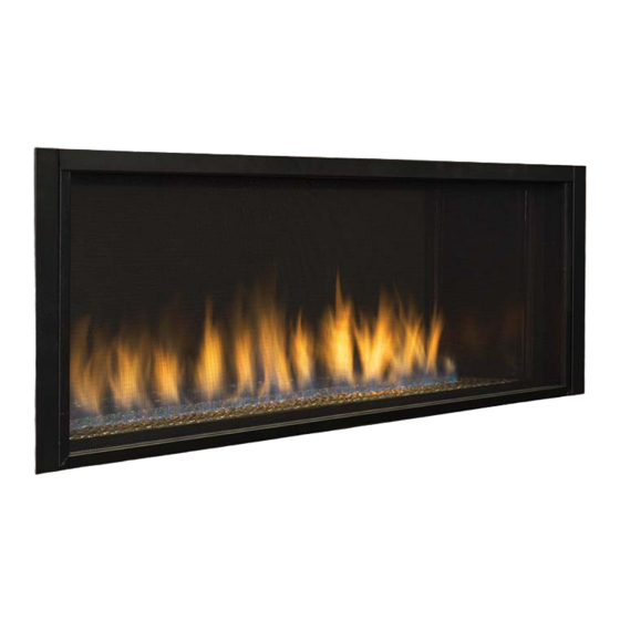
Direct-vent linear gas fireplace
Hide thumbs
Also See for DRL4543TEN:
- Installation and operation instructions manual (44 pages) ,
- Installation and operation instructions manual (48 pages) ,
- Quick start manual (2 pages)
Table of Contents
Advertisement
Quick Links
P/N 126718-01 Rev C 01/2015
P126718-01
INSTALLER: Leave this manual with the appliance.
CONSUMER: Retain this manual for future reference.
A barrier designed to reduce the risk of burns
from the hot viewing glass is provided with
this appliance and shall be installed for
the protection of children and other at-risk
individuals.
This appliance may be installed in an aftermarket permanently located, manufactured home (USA only) or mobile
home, where not prohibited by local codes. This appliance is only for use with the type of gas indicated on the
rating plate. This appliance is not convertible for use with other gases, unless a certified kit is used.
Cet appareil peut installé dans une maison préfabriquée (mobile) déjà installée à demeure, si les réglements
locaux le permettent. Ce appareil doit être utilisé uniquement avec le type de gaz indiqué sure la plaque
signalétique. Cet appareil ne peut être converti à d'autres gaz, sauf si une trousse de conversion est utilsée.
WARNING:
FIRE OR EXPLOSION HAZARD
Failure to follow safety warnings exactly could
result in serious injury, death, or property
damage.
— Do not store or use gasoline or other flammable
vapors and liquids in the vicinity of this or any
other appliance.
— WHAT TO DO IF YOU SMELL GAS
• Do not try to light any appliance.
• Do not touch any electrical switch; do not use
any phone in your building.
• Leave the building immediately.
• Immediately call your gas supplier from a
neighbor's phone. Follow the gas supplier's
instructions.
• If you cannot reach your gas supplier, call the
fire department.
— Installation and service must be performed by
a qualified installer, service agency or the gas
supplier.
PFS
®
C
US
Report No. F11 -026
Installateur : Laissez cette notice avec l'appareil.
Consommateur : Conservez cette notice pour consultation ultérieure.
L'écran pare-étincelles fourni avec ce foyer réduit le
risque de brûlure en cas de contact accidentel avec la
vitre chaude et doit être installé pour la protection Des
enfants et Des personnes à risques.
RISQUED'INDENDIE OU D'EXPLOSION
Le non-respect Des avertissements de sécurité pourrait
d'entraîner des blessures graves, la mort ou des dom-
mages matériels.
— Ne pas entreposer ni utilizer d'essence ni d'autres
— QUE FAIRE SI VOUS SENTEZ UNE ODEUR DE GAZ:
• Ne pas tenter d'allumer d'appareil.
• Ne touchez à aucan interrupteur. Ne pas vous servir des
• Sortez immédiatement de bâtiment.
• Appelez immédiatement votre fournisseur de gaz depuis
• Si vous ne pouvez rejoindre le fournisseur de gaz, appelez
— L'installation et l'entretien doivent être assurés par un
For more information, visit Superiorfireplaces.US.com
Installation and Operation Instructions
Superior™ Direct-Vent Linear Gas Fireplace
Models
DRL4543TEN
AVERTISSEMENT
vapeurs ou liquides inflammables dans le voisinage de
cet appareil ou de tout autre appareil.
téléphones se trouvant dans le bâtiment où vous trouvez.
un voisin. Suivez les instructions du fournisseur.
le service des incindies.
installateur ou un service d'entretien qualifié ou par le
fournisseur de gaz.
DRL4543TEP
Advertisement
Table of Contents

Subscribe to Our Youtube Channel
Related Manuals for Superior DRL4543TEN


Summary of Contents for Superior DRL4543TEN
- Page 1 Installation and Operation Instructions Superior™ Direct-Vent Linear Gas Fireplace ® Models P/N 126718-01 Rev C 01/2015 DRL4543TEN DRL4543TEP Report No. F11 -026 P126718-01 INSTALLER: Leave this manual with the appliance. Installateur : Laissez cette notice avec l’appareil. CONSUMER: Retain this manual for future reference.
- Page 2 DANGER HOT GLASS WILL CAUSE BURNS. DO NOT TOUCH GLASS UNTIL COOLED. NEVER ALLOW CHILDREN TO TOUCH GLASS. A barrier designed to reduce the risk of burns from the hot viewing glass is provided with this appliance and shall be installed for the protection of children and other at-risk individuals.
-
Page 3: Table Of Contents
Thank you for your purchase. We appreciate your TABLE OF CONTENTS business! Safety .....................3 Please carefully read and follow all instructions in this manual. Pay Local Codes ...................5 special attention to all warnings and safety information. Product Identification ..............5 Following these safety, care, and operation instructions will help Product Features ................5 ensure many years of dependable and enjoyable service from your Requirements for the Commonwealth of Massachusetts ....6... - Page 4 SAFETY Continued connected and sealed, carbon monoxide leakage (spillage) can occur. Installation and repair should be done by a qualified Carbon Monoxide Poisoning: Early signs of carbon monoxide poison- service person. The appliance should be inspected ing resemble the flu, with headaches, dizziness or nausea. If you have before use and at least annually by a professional these signs, the fireplace may not be working properly.
-
Page 5: Local Codes
SAFETY Continued LOCAL CODES 6. Have venting system inspected annually by a qualified service Install and use fireplace with care. Follow all local codes. In the ab- person. If needed, have venting system cleaned or repaired. See sence to local codes, use the current National Fuel Gas Code ANSI Cleaning and Maintenance, page 29. -
Page 6: Requirements For The Commonwealth Of Massachusetts
REQUIREMENTS FOR THE COMMONWEALTH OF MASSACHUSETTS COMMONWEALTH OF MASSACHUSETTS REQUIREMENTS Massachusetts Horizontal Vent Requirements These appliances are approved for installation in the US state of In the Commonwealth of Massachusetts, horizontal terminations Massachusetts if the following additional requirements are met: installed less than seven (7) feet above the finished grade must comply with the following additional requirements: •... -
Page 7: Pre-Installation
PRE-INSTALLATION LOCATION AND SPACE REQUIREMENTS CLEARANCES Determine the safest and most efficient location for your direct vent Minimum clearances to combustibles for the fireplace are as follows: fireplace. Make sure that rafters and wall studs are not in the way *Back and sides 1"... - Page 8 PRE-INSTALLATION Continued 17.50" Concrete Board 38" 53.25" Figure 4 - Installing Concrete Board Wall Figure 2 - Framing Clearances for One Sided Application 15.25" Mantel Mantel from Ref. Depth Ref. Top of Opening 12" 24" 9" 21" 38" 6" 18" 4"...
- Page 9 PRE-INSTALLATION Continued Figure 6 - DRL4543 Fireplace Series Dimensions 126718-01C Superiorfireplaces.US.com...
-
Page 10: Location Of Termination Cap
LOCATION OF TERMINATION CAP Fixed Openable Fixed Closed Closed Openable TERMINATION CAP AIR SUPPLY INLET GAS METER RESTRICTED AREA (TERMINATION PROHIBITED) A = clearance above grade, veranda, porch, deck, or I = clearance to service regulator vent outlet [*72" (182.9 cm) balcony [*12"... -
Page 11: Venting Installation
VENTING INSTALLATION NOTICE: Read these instructions completely before WARNING: This gas fireplace and vent assembly attempting installation. must be vented directly to the outside. The venting system must NEVER be attached to a chimney serving These models are tested and approved for use with an IHP (direct a separate solid fuel burning appliance. - Page 12 VENTING INSTALLATION Continued INSTALLATION PLANNING There are two basic types of direct vent installation: • Horizontal Termination • Vertical Termination Installing the Horizontal Termination Vent System These instructions should be used as a guideline and do not supersede local codes in any way. Install venting according to local codes, these instructions, the current National Fuel Gas Code (ANSI-Z223.1) in the USA or the current standards of CAN/CGA-B149.1 in Canada.
- Page 13 VENTING INSTALLATION Continued NOTE: The firestop/spacer may also be installed over the 9. Continue installation of horizontal/inclined sections— Continue with the installation of the straight vent sections opening at the interior side of the framing. in horizontal/inclined run. Install support straps every 13.
- Page 14 VENTING INSTALLATION Continued *Use silicone caulking to Maximum wall thickness seal the top and sides of 9 1/4” (235 mm)** the termination, up to the Interior Surface of underlayment, stucco, or Finished Wall Exterior Surface of Siding masonry wall surface. Maximum Extent of Exterior Surface of Vent Run Sections...
- Page 15 VENTING INSTALLATION Continued Connecting the vent pipe 2. Push the vent component against the collar until it fully engages, then twist the component clockwise, running the Direct-vent system components are unitized concentric pipe dimples down and along the incline channels until they seat components featuring positive twist lock connections (Figure 11 at the end of the channels.
- Page 16 VENTING INSTALLATION Continued GROUND FLOOR INSTALLATION 1' Pipe Min. On Recommended Applications: 90° Elbow Horizontal Run • Through the wall using round or square termination V + 90· Elbow Wall Firestop (V) Vertical Required (H) Horizontal Horizontal High Minimum Vertical Pipe Maximum Wind Square 53"...
- Page 17 VENTING INSTALLATION Continued Install the Vertical Termination Vent System Vertical (Offset) Installation These instructions should be used as a guideline and do not super- 1. Analyze the vent route and determine the number of vent sede local codes in any way. Install venting according to local codes, sections and elbows required—See Effective Vent Length these instructions, the current National Fuel Gas Code (ANSI-Z223.1) on table 2, Page 14 for more information.
- Page 18 VENTING INSTALLATION Continued 10. Install the roof flashing—Extend the vent sections through the roof structure. Install the roof flashing over the vent section and position such that the vent column rises verti- cally (use carpenters level). Nail along perimeter to secure flashing or adjust roofing to overlap the flashing edges at top and sides only and trim where necessary.
- Page 19 VENTING INSTALLATION Continued 12. Install the vertical termination—The final step involves Vertical termination Configurations installation of the SV4.5CGV-1 vertical termination. Align Figure 23 and 24 show the configurations for vertical termination. the termination over the end of the previously installed section, adjusting the radial alignment until the four (4) locking dimples of the termination are aligned with the inlets of the four (4) incline channels of the last vent sec-...
- Page 20 VENTING INSTALLATION Continued FIREPLACE INSTALLATION CHECK GAS TYPE PARTS LIST FOR VENTING KITS AND COMPONENTS Use proper gas type for the fireplace unit you are installing. If you have conflicting gas types, do not install fireplace. See retailer where you Table 3: Listed Components purchased the fireplace for proper fireplace according to your gas type.
-
Page 21: Fireplace Installation
FIREPLACE INSTALLATION Continued External Regulator Equipment Shutoff Valve with Vent Pointing with 1/8" NPT Tap* Propane/LP Natural - From Down Supply Tank Gas Meter (5.5" W.C. to 10.5" W.C. Pressure) Propane/LP From Approved External Regulator Flexible (11" W.C. to 14" Gas Line W.C. - Page 22 FIREPLACE INSTALLATION Continued CHECKING GAS CONNECTIONS Equipment Shutoff Valve WARNING: Test all gas piping and connections, Propane/LP internal and external to unit, for leaks after installing Supply Tank or servicing. Correct all leaks at once. WARNING: Never use an open flame to check for a leak.
- Page 23 FIREPLACE INSTALLATION Continued Figure 32 - Latch Opener Replacing Glass Door 1. Position door frame in front of firebox opening tilting top of door about 45° toward you. Insert bottom flange of glass door into the retaining channel at the bottom of firebox (see Figure 33). Make sure door is center with firebox opening.
- Page 24 FIREPLACE INSTALLATION Continued UPGRADING DRL4543 TO SEE-THRU APPLICATION Glowing embers and glass pebbles are included with your fireplace. Install these items while glass doors are open and/or removed. Removing Rear Panel 1. Place glass pebbles in a single layer evenly on the pebble pan. 1.
- Page 25 FIREPLACE INSTALLATION Continued Retaining Bracket Figure 38 - Installing Access Door Retaining Brackets for See- Thru Applications Figure 36 - Removing Mount Bracket for See-Thru Applications Removing False Door 1. In the rear of the fireplace, remove false door just as you would remove the front glass door.
- Page 26 FIREPLACE INSTALLATION Continued UPGRADING DRL4543 TO INDOOR/OUTDOOR SEE-THRU Fireplace APPLICATION Face WARNING: LDSTI must be installed before install- ing LDSTO. Installing Exterior Door 1. Center and level exterior door on rear face of the see-thru fireplace. Exact dimensions for the location of the door are shown in Figure 2.
-
Page 27: Operation
OPERATION FOR YOUR SAFETY LIGHTING READ BEFORE LIGHTING INSTRUCTIONS NOTICE: During initial operation of new fireplace, WARNING: If you do not follow these instructions burning will give off a paper-burning smell. Orange exactly, a fire or explosion may result causing property flame will also be present. -
Page 28: Inspecting Burners
INSPECTING BURNERS Check pilot flame pattern and burner flame patterns often. PILOT ASSEMBLY The pilot assembly is factory preset for the proper flame. Alterations may have occurred during shipping and handling. The pilot is located Pilot on right hand side of burner. Burner The flame must envelope 1/4"... -
Page 29: Cleaning And Maintenance
CLEANING AND MAINTENANCE WARNING: Turn off fireplace and let cool before CAUTION: Do not vacuum if pieces are hot. cleaning. Use only glass door replacement intended for this fireplace (see Replacement Parts, page 32 for detail on ordering). No substitutions CAUTION: You must keep control areas, burners may be made. -
Page 30: Gas Control Module System
GAS CONTROL MODULE SYSTEM The module has 2 special features built into the system. BATTERY BACK-UP Continuous Pilot Feature This fireplace is equipped with a battery back-up. If the power was to go out on the fireplace, the battery back-up allows the fireplace to This allows the change from a spark to pilot system to a standing remain operational. - Page 31 REMOTE CONTROL OPERATION Continued • Temperatures may be displayed in degrees F (factory default) or degrees C. Press the up and down buttons simultaneously to change between degrees F. and C. MODE Zone Cont. ROOM Pilot MODES OF OPERATION ROOM TEMP Operation modes: Zone °...
-
Page 32: Specifications
REMOTE CONTROL OPERATION Continued SPECIFICATIONS DRL4543TEN LIGHT ADJUSTMENT • Rating: 35,000/22,000 Btu/hr • Transmits a light setting command to the control module to adjust the light output level. • Gas Type: Natural Gas Only • Ignition: Electronic • Available settings are 0 (off) – 6 with a factory default of 0 (off). -
Page 33: Wiring Diagram
WIRING DIAGRAM COMM Blk. Brown Yellow Orange 126718-01C Superiorfireplaces.US.com... -
Page 34: Troubleshooting
TROUBLESHOOTING WARNING: Turn off fireplace and let cool before servicing. Only a qualified service person should service and repair fireplace. CAUTION: Never use a wire, needle or similar object to clean pilot. This can damage pilot unit. Note: All troubleshooting items are listed in order of operation. OBSERVED PROBLEM POSSIBLE CAUSE REMEDY... -
Page 35: Accessories
TROUBLESHOOTING Continued WARNING: If you smell gas • Shut off gas supply. • Do not try to light any appliance. • Do not touch any electrical switch; do not use any phone in your building. • Immediately call your gas supplier from a neighbor’s phone. Follow the gas supplier’s instructions. •... -
Page 36: Parts
PARTS BURNER ASSEMBLY This list contains replaceable parts used in your fireplace. When ordering parts, follow the instructions listed under Replacement Parts on page 32 of this manual. Superiorfireplaces.US.com 126718-01C... - Page 37 32 of this manual. WARNING: Contact an IHP dealer to obtain any of these parts. Never use substitute materials not approved by IHP. Use of non-approved parts can result in poor performance and safety hazards. DRL4543TEN DRL4543TEP CATALOG PART NO.
- Page 38 PARTS MODELS: DRL4543TEN AND DRL4543TEP DRL4543TEN DRL4543TEP CATALOG PART NO. DESCRIPTION (F1262) (F1263) QTY. J7872 800069-01 Top Assembly Fireplace • • J7874 125847-01 Top Spacer • • J7875 125757-02 Top Nailing Flange • • J7876 125805-01 Rear Panel • •...
-
Page 39: Warranty
THE WARRANTY Innovative Hearth Products ("IHP") 20 Year Limited Warranty warrants your Superior™ Brand gas fireplace, Stove or Insert ("Product") to be free from defects in materials and workmanship at the time of manufacture. The Product body and firebox carry the 20 Year Limited Warranty. Ceramic glass carries the 20 Year Limited Warranty against thermal breakage only. - Page 40 WARRANTY KEEP THIS WARRANTY Model (located on product or id tag) Burner System _________ Cast Stove ___________ Serial No. (located on product or identification tag) ___________________ Date Purchased ______________________ Keep receipt for warranty verification. Innovative Hearth Products reserves the right to make changes at any time, without notice, in design, materials, specifications, prices and also to discontinue colors, styles and products.
Need help?
Do you have a question about the DRL4543TEN and is the answer not in the manual?
Questions and answers