Table of Contents
Advertisement
Quick Links
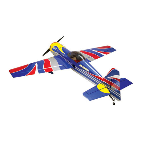
85cc Sukhoi SU-26MM
Specifications
Wingspan ........................................97 in (2464mm)
1
Overall Length ....... 91
/
in (2315mm) with spinner
8
Wing Area ...........................1762 sq in (114 sq dm)
Flying Weight ............... 21.5–24 lb (9.75–10.89 kg)
Assembly mAnuAl
Engine Size .......................................... 58–85cc gas
Radio........................................... 7-channel or more
Servos .........................................................6 servos
(7 if using two rudder servos instead of one)
Spinner Size .............................................. 4
Hardware Included ..............................................Yes
1
/
-inch
4
Advertisement
Table of Contents

Related Manuals for Hangar 9 85cc Sukhoi SU-26MM


Summary of Contents for Hangar 9 85cc Sukhoi SU-26MM
- Page 1 85cc Sukhoi SU-26MM Assembly mAnuAl Specifications Wingspan ........97 in (2464mm) Engine Size .......... 58–85cc gas Overall Length ..91 in (2315mm) with spinner Radio........... 7-channel or more Wing Area ......1762 sq in (114 sq dm) Servos ............6 servos Flying Weight ....21.5–24 lb (9.75–10.89 kg) (7 if using two rudder servos instead of one) Spinner Size ..........
-
Page 2: Table Of Contents
Table of Contents Using the Manual ..............3 Required Tools and Adhesives . -
Page 3: Using The Manual
Before Starting Assembly Before beginning the assembly of the 85cc Sukhoi SU-26MM, remove each part from its bag for inspection. Closely inspect the fuselage, wing panels, rudder, and stabilizer for damage. If you find any damaged or missing parts, contact the place of purchase. -
Page 4: Radio And Power Systems Requirements
Radio and Power Systems Requirements • 48-inch extension (JRPA104) (2) • Fuel Dot (HAN115) • 12-inch extension (JRPA098) (5) • JR Charge Jack Switch (JRPA004) (3) • 36-inch Servo Lead Extension (JRPA103) • Choke Ring (JRPA029 for throttle servo lead) •... -
Page 5: Warranty Period
Warranty Period Exclusive Warranty- Horizon Hobby, Inc., (Horizon) warranties that the Products purchased (the "Product") will be free from defects in materials and workmanship at the date of purchase by the Purchaser. Limited Warranty (a) This warranty is limited to the original Purchaser ("Purchaser") and is not transferable. REPAIR OR REPLACEMENT AS PROVIDED UNDER THIS WARRANTY IS THE EXCLUSIVE REMEDY OF THE PURCHASER. -
Page 6: Questions, Assistance, And Repairs
Questions, Assistance, and Repairs Your local hobby store and/or place of purchase cannot provide warranty support or repair. Once assembly, setup or use of the Product has been started, you must contact Horizon directly. This will enable Horizon to better answer your questions and service you in the event that you may need any assistance. -
Page 7: Safety, Precautions, And Warnings
Safety, Precautions, and Warnings This model is controlled by a radio signal that is subject to interference from many sources outside your control. This interference can cause momentary loss of control so it is advisable to always keep a safe distance in all directions around your model, as this margin will help to avoid collisions or injury. -
Page 8: Aileron Servo Installation
Aileron Servo Installation Required Parts Step 3 • Wing panel (left and right) Tip the wing so the root is facing down and lower the • 4-40 x 4-40 ball end w/hardware (2) weight through the wing. • Control horn (2) •... - Page 9 Step 5 Step 7 Use the string to pull the extension through the wing. Tape Thread the control horn onto the control horn screw so the the extension so it will not fall back into the wing. bottom of the horn is 25/32 inch (20mm) from the surface of the aileron.
- Page 10 Step 9 Step 11 Attach the ball end to the top side of the servo arm Temporarily remove the setscrew from the control horn using the ball end hardware, including the cone washer and remove the clevis. Thread the clevis onto the 3-inch between the servo arm and ball end.
-
Page 11: Elevator Servo Installation
Elevator Servo Installation Required Parts Step 3 • 4-40 x 4-40 ball end w/hardware (2) Attach the ball end on the side of the servo arm that • Control horn (2) is closest to the root of the stabilizer using the ball end hardware. - Page 12 Step 5 Step 6 Attach the ball end to the servo horn using the hardware Repeat Steps 1 through 5 for the remaining elevator servo provided with the ball end. The attachment point will be and linkage. -inch (38mm) from the center of the servo horn.
-
Page 13: Rudder And Rudder Servo Installation
Rudder and Rudder Servo Installation Required Parts Step 2 • Control horn (2) • Steering spring (2) Assemble the rudder linkage using a 4 -inch (114mm) • Rudder • Fuselage linkage, ball end and control horn. The control horn is then threaded on the control horn screw so the bottom of •... - Page 14 Step 4 Step 6 Attach the ball end to the servo horn using the hardware Drill each of the locations using a drill and 3/32-inch provided with the ball end. The attachment point will be (2.5mm) drill bit. -inch (38mm) from the center of the servo horn.
- Page 15 Step 8 Step 10 Apply a few drops of thin CA into each of the two holes to Attach the tail gear assembly to the bottom of the fuselage harden the wood. This will help in preventing the screws using two #6 x 5/8-inch socket head sheet metal screws.
-
Page 16: Landing Gear Installation
Landing Gear Installation Required Parts o Step 2 • Fuselage assembly • Main landing gear Secure the axle to the main landing gear. • #8 washer (4) • 8-32 locknut (4) • Axle w/nut (2) • #4 washer (4) • 4-40 blind nut (4) •... - Page 17 o o Step 4 Step 7 Attach the wheel to the axle using two 5/32-inch wheel Place the fuselage on a level surface. Slide the wheel pant collars. The collars are placed on either side of the wheel. into position. The pant must be positioned so it is parallel with the fuselage as shown.
- Page 18 o o Step 9 Step 11 Drill the locations marked in the previous step using a Secure the wheel pant to the landing gear using two drill and 9/64-inch (3.5mm) drill bit. 4-40 x 1/2-inch socket head screws and two #4 washers. o...
-
Page 19: Stabilizer Installation
Stabilizer Installation Required Parts Step 2 • Fuselage assembly • Stabilizer/elevator (2) Attach a 48-inch (1220mm) servo extension to the • Stabilizer tube • #4 washer (4) elevator servo. Secure the extension using a commercially available connector, heat shrink tubing or string so it will •... -
Page 20: Engine Installation (Da85)
Engine Installation (DA85) Required Parts Step 2 • Fuselage assembly • 90-degree snap link Use a drill and 3/32-inch (2.5mm) drill bit to drill the four • 1/4-inch lock washer (4) • 1/4-20 blind nut (4) locations for mounting the engine. •... - Page 21 Step 4 Step 6 Drill the four locations using a drill and 5/16-inch (8mm) Position the throttle servo into the opening next to the drill bit. The blind nuts are then installed into the backside fuel tank. The output of the servo faces toward the front of of the firewall.
- Page 22 Step 8 Step 10 Attach the throttle linkage to the carburetor using a Bend the pushrod wire 90-degrees at the mark made in 2mm x 4-40 ball link 2mm x 10mm socket head screw the previous step. Use a pin drill and 3/32-inch (2.5mm) and 2mm lock nut.
- Page 23 Step 12 Step 13 Drill a 3/8-inch (9.5mm) hole in the side of the fuselage Attach the battery to power the ignition system on the top to mount the fuel dot to refill your model without having to of the engine box.
- Page 24 Step 15 Step 16 Mount the switch for the ignition system on the side of the Attach the Pitts-style muffler to the engine at this time. fuselage as shown. Step 17 Remove the material from the cowling to clear the exhaust system and to provide cooling air to pass over the engine.
- Page 25 Installing the MTW 110 Canister and Header Step C (Available from Desert Aircraft) Carefully remove the section from the fuselage. Step A Use a felt-tipped pen to draw lines vertically that connect the bottom of the fuselage to the sides of the opening. ...
- Page 26 Step E Step F Remove the covering from the bottom of the fuselage. Use a covering iron to seal the edges of the covering You may want to save the covering in case it is needed inside the fuselage. for small repairs.
- Page 27 Step G Step H Remove the covering from the bottom of the fuselage and Remove the material from the cowling to clear the exhaust cut the stringers as shown. Repeat Steps D through F to system and to provide cooling air to pass over the engine. seal the covering around the opening.
-
Page 28: Radio System Installation
Radio System Installation Required Parts Step 2 • Fuselage assembly • Receiver Mount radio switch (or switches) in the rear switch holes • Receiver battery • Foam and the ignition switch in one of the front switch holes. • Tie wraps Required Tools and Adhesives •... -
Page 29: Canopy Installation
Canopy Installation Required Parts Step 2 • Fuselage assembly • Pilot bust Use 30-minute epoxy to secure the pilot bust to the • Canopy canopy hatch. Required Tools and Adhesives • Canopy glue • Felt-tipped pen • Painter's tape •... -
Page 30: Radio Setup
Step 5 Step 6 Sand the hatch and canopy where they contact each other Slip a piece of waxed paper between the hatch and using sandpaper. Clean the area using rubbing alcohol fuselage and install the canopy hatch onto the fuselage and a paper towel. -
Page 31: Control Throws
Rates and Expos Use Expo to soften the feel of the model. On high 3D Use low rate settings for all flying except for 3D rates, use quite a bit of expo. The goal on 3D rates is to aerobatics. For precision flying or general sport hot- get the model to feel the same around neutral as it does dogging, the low rate throws are perfect, even for snap on low rates. -
Page 32: Recommended Center Of Gravity (Cg)
Computer Radio Enhancements A computer radio will allow you to do quite a bit of fine-tuning to the feel of the Sukhoi, which will make aerobatics even easier. Recommended Center of Gravity (CG) An important part of preparing the aircraft for flight is properly balancing the model. -
Page 33: Preflight
Preflight Never attempt to make full throttle dives! For those of you who are veterans of large models, this is old news. But to you newcomers to the world of large Large models perform much more like full-size aircraft models, this is very important information. than small models. -
Page 34: 2007 Official Ama National Model Aircraft Safety Code
2007 Official AMA National Model Aircraft Safety Code GENERAL 8. I will not operate model aircraft carrying pyrotechnic devices which explode burn, or propel a projectile 1. A model aircraft shall be defined as a non-human- of any kind. Exceptions include Free Flight fuses or carrying device capable of sustained flight in the devices that burn producing smoke and are securely atmosphere. - Page 35 2007 Official AMA National Model Aircraft Safety Code Radio Control 7. With the exception of events flown under official AMA rules, no powered model may be flown outdoors closer 1. All model flying shall be conducted in a manner to than 25 feet to any individual, except for the pilot and avoid over flight of unprotected people.
- Page 36 © 2007 Horizon Hobby, Inc. 4105 Fieldstone Road Champaign, Illinois 61822 (877) 504-0233 horizonhobby.com 11219...
Need help?
Do you have a question about the 85cc Sukhoi SU-26MM and is the answer not in the manual?
Questions and answers