Table of Contents
Advertisement
Quick Links
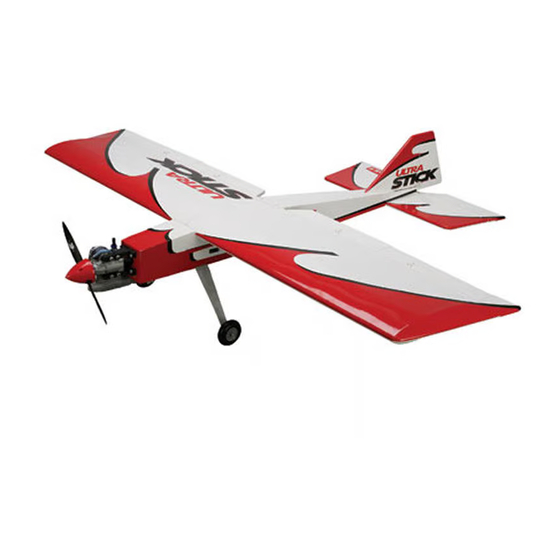
Ultra Stick
40 ARF
™
Assembly Manual
Specifications
Wingspan: ..........................................................57.75 in (1467mm)
Length: ................................................................... 51 in (1295mm)
Wing Area: ................................... 700 sq in (715 with quad flaps)
Weight: .............................................................. 5–6 lb (2.3–2.7 kg)
Radio: ............................................................4-channel or greater
Engine: ..................................... .40–.46 2-stroke, .56–.82 4-stroke
Advertisement
Chapters
Table of Contents

Related Manuals for Hangar 9 Ultra Stick 40 ARF


Summary of Contents for Hangar 9 Ultra Stick 40 ARF
- Page 1 Ultra Stick 40 ARF ™ Assembly Manual Specifications Wingspan: ............57.75 in (1467mm) Length: ..............51 in (1295mm) Wing Area: ........700 sq in (715 with quad flaps) Weight: .............. 5–6 lb (2.3–2.7 kg) Radio: ............4-channel or greater Engine: ........40–.46 2-stroke, .56–.82 4-stroke...
-
Page 2: Table Of Contents
Daily Flight Checks ...............44 Safety, Precautions and Warnings ........44 Warranty Information ............45 Instructions for Disposal of WEEE by Users in the European Union .........46 2009 Official Academy of Model Aeronautics Safety Code ........47 Hangar 9 Ultra Stick 40 ARF Assembly Manual... -
Page 3: Included Parts Listing
2 x 1/4-inch dowel rods Anti-rotation pins 3mm machine screw Tank Hardwood wing spar Clunk 1-inch white covering strip Center wing joint Aluminum tubing Vent, fill and overflow Balsa block Fuel tank Hangar 9 Ultra Stick 40 ARF Assembly Manual... -
Page 4: Using The Manual
• Metered Glow Driver with Ni-Cd & Charger (HAN7101) • 2-Cycle Sport Plug (EVOGP1) • Manual Fuel Pump (HAN118) HAN101 – Sealing Iron HAN141 – Sealing Iron Sock The Spektrum trademark is used with permission of Bachmann Industries, Inc. Hangar 9 Ultra Stick 40 ARF Assembly Manual... -
Page 5: Aileron Installation (Aileron Only)
This section covers the installation of the ailerons for the two aileron versions of your model. Step 1 Check to make sure you have the correct aileron. The trim will match the bottom of the wing. Hangar 9 Ultra Stick 40 ARF Assembly Manual... - Page 6 Do not use CA accelerator on the hinges. The CA Repeat Steps 1 through 6 to install the remaining aileron. must be allowed to soak into the hinge and surrounding wood. Hangar 9 Ultra Stick 40 ARF Assembly Manual...
-
Page 7: Aileron And Flap Installation(Quad Flap Only)
Check to make sure you have the correct aileron. The trim will match the bottom of the wing. note: The flap and aileron have not been seperated at this time and are still taped together as shipped. Hangar 9 Ultra Stick 40 ARF Assembly Manual... - Page 8 Also check that the aileron can move freely without rubbing at on the aileron to make sure the hinges are secure. If not, apply the wing tip. more CA to the loose hinge. Hangar 9 Ultra Stick 40 ARF Assembly Manual...
-
Page 9: Joining The Wing Panels
This is so you can orient the joiner correctly in this section of the manual. Step 8 Repeat Steps 1 through 7 to attach the remaining aileron and flap to the wing. Hangar 9 Ultra Stick 40 ARF Assembly Manual... - Page 10 Apply epoxy in the joiner pocket and all sides of the joiner, correctly. including the top and bottom edges. Also coat the exposed wood on the root rib with epoxy. Start with one panel, insert the joiner, then the opposite panel. Hangar 9 Ultra Stick 40 ARF Assembly Manual...
-
Page 11: Completing The Wing Assembly
The wing has no dihedral. It will rest flat on your work surface while the epoxy cures. Make sure to cover your work surface with waxed paper so you don’t accidentally glue the wing to your work surface. Hangar 9 Ultra Stick 40 ARF Assembly Manual... - Page 12 1/16-inch (1.5mm) inside between the wing panels. the line drawn. Hint: Add a radius to the front edge of the dowels to make it easier to install them in the fuselage. Hangar 9 Ultra Stick 40 ARF Assembly Manual...
-
Page 13: Horizontal Stabilizer Installation
Use a T-pin at holes in the fuselage. the rear of the stabilizer as a pivot and to keep the stabilizer in position on the fuselage. Parallel Hangar 9 Ultra Stick 40 ARF Assembly Manual... -
Page 14: Vertical Fin Installation
Do not press on the knife when cutting the covering. Cutting into the wood of the stabilizer will weaken it and cause it to fail in flight. Hangar 9 Ultra Stick 40 ARF Assembly Manual... -
Page 15: Preparation For Tail Gear Installation
Use a pin vise and 1/8- inch (3mm) drill bit to drill a hole that is 1-inch (25mm) deep in the rudder. Hangar 9 Ultra Stick 40 ARF Assembly Manual... -
Page 16: Rudder Installation
Hobby knife with #11 blade Thin CA T-pins Step 1 Use a pin vise and 1/16-inch drill bit to drill a hole in the center of each hinge on both the fin and rudder. Hangar 9 Ultra Stick 40 ARF Assembly Manual... - Page 17 If you are installing the tail wheel, use 30-minute epoxy to glue the tail gear bushing into the fuselage. Hangar 9 Ultra Stick 40 ARF Assembly Manual...
-
Page 18: Elevator Installation
Use a rotary tool and sanding drum to make a notch so the elevator does not bind against the wire. Hangar 9 Ultra Stick 40 ARF Assembly Manual... -
Page 19: Radio Installation
Use a #1 Phillips screwdriver to thread a servo mounting screw into each of the holes in the servo tray. Apply 2–3 drops of thin CA in each hole to harden the surrounding wood. Hangar 9 Ultra Stick 40 ARF Assembly Manual... - Page 20 Use a hobby knife and #11 blade to trim the mounting locations for the control horn mounting screws. covering so the wire can exit the fuselage. Hangar 9 Ultra Stick 40 ARF Assembly Manual...
- Page 21 (14mm) and 3/8-inch (9.5mm) from the center of the servo horn. note: If you are building the tail dragger version it is not necessary to enlarge the hole that is 3/8-inch (9.5mm) from the center of the servo horn. Hangar 9 Ultra Stick 40 ARF Assembly Manual...
-
Page 22: Aileron Servo Installation(Aileron Only) Or Flap Servo Installation (Quad Flap Version)
Step 1 Use a hobby knife and #11 blade to remove the covering for the inboard servo in the bottom of the wing. Hangar 9 Ultra Stick 40 ARF Assembly Manual... - Page 23 Use a pin vise and 1/16- wing as shown. inch (1.5mm) drill bit to drill the holes for the screws. Use 2–3 drops of thin CA to harden the surrounding wood. Hangar 9 Ultra Stick 40 ARF Assembly Manual...
- Page 24 Step 6 Slide a clevis retainer on a clevis, then thread the clevis 12-turns on a 6-inch (152mm) pushrod wire. Connect the clevis to the control horn as shown. Hangar 9 Ultra Stick 40 ARF Assembly Manual...
-
Page 25: Aileron Servo Installation(Quad Flap Version)
Step 1 Use string to secure a 9-inch (230mm) servo extension to the aileron servo. Step 11 Repeat Steps 1 through 10 to install the remaining servo. Hangar 9 Ultra Stick 40 ARF Assembly Manual... -
Page 26: Step
CA to harden the surrounding wood. Step 5 Slide a clevis retainer on a clevis, then thread the clevis 12-turns on a 6-inch (152mm) pushrod wire. Connect the clevis to the control horn as shown. Hangar 9 Ultra Stick 40 ARF Assembly Manual... -
Page 27: Step
With the control surface centered, use a felt-tipped pen to mark the pushrod where it crosses the hole of the servo horn. Use pliers to bend the pushrod 90-degrees at the mark. Hangar 9 Ultra Stick 40 ARF Assembly Manual... -
Page 28: Landing Gear Installation
File a flat on the axle that is the first 1/4- inch (6mm) and a 1/4-inch (6mm) wide area 1-inch (25mm) from the end of the axle. Step 10 Repeat Steps 1 throught 9 to install the remaining servo. Hangar 9 Ultra Stick 40 ARF Assembly Manual... - Page 29 Apply threadlock to the setscrews that will be used in the two 4mm wheel collars. The collars are on either side of the wheel. Make sure to tighten the setscrews on the flat areas of the axle made in the previous step. Hangar 9 Ultra Stick 40 ARF Assembly Manual...
-
Page 30: Engine Installation
Step 1 Use a hobby knife with a #11 blade to remove the covering to expose the blind nuts and opening for the fuel tank at the front of the fuselage. Hangar 9 Ultra Stick 40 ARF Assembly Manual... - Page 31 (152mm) from one end of the tube. Insert the tube in the on the tube, but do not glue it at this time. engine. hole drilled in the previous step. Hangar 9 Ultra Stick 40 ARF Assembly Manual...
- Page 32 Step 7 Position the engine between the engine mount rails. Use a felt- tipped pen to mark the firewall where the throttle pushrod tube will be positioned. Hangar 9 Ultra Stick 40 ARF Assembly Manual...
- Page 33 Use medium CA to glue the tube to the firewall and former. Step 14 Attach the bend in the 17 -inch (445mm) pushrod to the carburetor arm on your engine. Hangar 9 Ultra Stick 40 ARF Assembly Manual...
-
Page 34: Nose Gear Installation
Step 1 File a flat on the axle that is the first 1/4-inch (6mm) and a 1/4-inch (6mm) wide area 1-inch (25mm) from the end of the axle. Hangar 9 Ultra Stick 40 ARF Assembly Manual... - Page 35 This will leave a mark so a or dislodge during hard landings. flat can be filed in the following steps. Step 4 Slide the pushrod wire into the tube in the fuselage. Hangar 9 Ultra Stick 40 ARF Assembly Manual...
-
Page 36: Fuel Tank Assembly
Fuel tube, red Fuel tube, green Fuel tube, pink 3mm x 20mm machine screw Tools and Adhesives Phillips screwdriver: #1 Step 1 Locate the items necessary to assemble the fuel tank. Hangar 9 Ultra Stick 40 ARF Assembly Manual... - Page 37 If not, shorten the tube slightly so the clunk place a kink in the tube. does not bind inside the tank. Vent Line Top View To Muffler To Carburetor Vent Line (faces top of fuselage) Clunk Side View Hangar 9 Ultra Stick 40 ARF Assembly Manual...
-
Page 38: Throttle Pushrod Connection And Fuel Tank Installation
Box wrench (to fit propeller nut) Step 1 Use a pin vise and 5/64-inch (2mm) drill bit to enlarge the hole that is 1/2-inch (13mm) from the center of the servo horn. Hangar 9 Ultra Stick 40 ARF Assembly Manual... - Page 39 Use foam to keep the tank from moving in the fuselage. Glue the balsa block in place using medium CA to secure the tank. Hangar 9 Ultra Stick 40 ARF Assembly Manual...
-
Page 40: Final Radio Installation
Hobby knife with #11 blade Phillips screwdriver: #1 Step 1 Remove the covering from the side of the fuselage using a hobby knife and #11 blade. Insert the wires from the switch into the hole. Hangar 9 Ultra Stick 40 ARF Assembly Manual... -
Page 41: Center Of Gravity
Use caution not to damage the covering around the control horn by applying too much heat. After the first flights, the CG position can be adjusted for your personal preference. Hangar 9 Ultra Stick 40 ARF Assembly Manual... -
Page 42: Quad Flaps
This maneuver is sometimes called a Harrier. With crow activated, the Ultra Stick 40 has reduced tendency to tip stall. This is because the up ailerons at the Hangar 9 Ultra Stick 40 ARF Assembly Manual... -
Page 43: Flight Preparations
(a bit of down elevator), as the intention of short takeoff flaps is to get off the ground in as short a distance as possible. Just turn off the flap shortly after takeoff. Hangar 9 Ultra Stick 40 ARF Assembly Manual... -
Page 44: Safety Do's And Don'ts For Pilots
Check that all trim levers are in the proper location. Step 7 All servo pigtails and switch harness plugs should be secured in the receiver. Make sure that the switch harness moves freely in both directions. Hangar 9 Ultra Stick 40 ARF Assembly Manual... -
Page 45: Warranty Information
Product. This warranty does not cover damage due to improper installation, operation, maintenance, or attempted repair by anyone other than Horizon. Return of any goods by Purchaser must be approved in writing by Horizon before shipment. Hangar 9 Ultra Stick 40 ARF Assembly Manual... -
Page 46: Instructions For Disposal Of Weee By Users In The European Union
Horizon Product Support 4105 Fieldstone Road Champaign, Illinois 61822 Please call 877-504-0233 or e-mail us at productsupport@ horizonhobby.com with any questions or concerns regarding this product or warranty. Hangar 9 Ultra Stick 40 ARF Assembly Manual... -
Page 47: 2009 Official Academy Of Model Aeronautics Safety Code
Model Rocketry Safety Code; however, they may not be launched from model aircraft. Officially designated AMAAir Show Teams (AST) are authorized to use devices and practices as defined within the Air Show Advisory Committee Document. Hangar 9 Ultra Stick 40 ARF Assembly Manual... - Page 48 Horizon Hobby UK Horizon Hobby Deutschland GmbH Horizon Hobby USA Units 1-4 Ployters Rd Hamburger Strasse 10 4105 Fieldstone Road Staple Tye 25335 Elmshorn Champaign, Illinois 61822 Harlow, Essex Germany CM18 7NS +49 4121 46199 60 (877) 504-0233 United Kingdom +44 (0) 1279 641 097 ©...
Need help?
Do you have a question about the Ultra Stick 40 ARF and is the answer not in the manual?
Questions and answers