Table of Contents
Advertisement
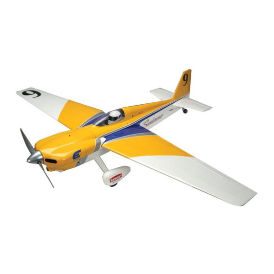
Sundowner 50 ARF
Specifications
Wingspan ........................................63 in (1600mm)
Wing area .............................572 sq in (36.9 sq dm)
Length ..........................................47.4 in (1204mm)
Weight ................................... 6–6.75 lb (2.72–3 kg)
Assembly mAnuAl
Engine ..................................... .56–.82 Four-Stroke
....................................... .40–.52 Two-Stroke
...........................................Power 46 Electric
Radio..............4-Channel w/5 Servos (4 for electric)
Advertisement
Table of Contents

Related Manuals for Hangar 9 Sundowner 50 ARF


Summary of Contents for Hangar 9 Sundowner 50 ARF
- Page 1 Sundowner 50 ARF Assembly mAnuAl Specifications Wingspan ........63 in (1600mm) Engine ........56–.82 Four-Stroke Wing area ......572 sq in (36.9 sq dm) ........40–.52 Two-Stroke Length ..........47.4 in (1204mm) ...........Power 46 Electric Weight ........6–6.75 lb (2.72–3 kg) Radio....4-Channel w/5 Servos (4 for electric)
-
Page 2: Table Of Contents
Table of Contents Using the Manual ..............3 Required Tools and Adhesives . -
Page 3: Using The Manual
Using the Manual This manual is divided into sections to help make assembly easier to understand, and to provide breaks between each major section. In addition, check boxes have been placed next to each step to keep track of each step completed. Steps ... -
Page 4: Radio And Power Systems Requirements
Radio and Power Systems Requirements • 4-channel radio system (minimum) w/receiver • Large Servo Arms (JSP98060) • JR Standard Switch (JSP98010) • 700mAh Ni-Cd 4-cell (JSP91010) • Y-harness (Ailerons) (JSP98020) (Required when using 4-channel radio) or 6-inch Servo Lead Extension (JSP98110); (2) when mixing ailerons through the radio •... -
Page 5: Warranty Period
Warranty Period Exclusive Warranty- Horizon Hobby, Inc., (Horizon) warranties that the Products purchased (the "Product") will be free from defects in materials and workmanship at the date of purchase by the Purchaser. Limited Warranty (a) This warranty is limited to the original Purchaser ("Purchaser") and is not transferable. REPAIR OR REPLACEMENT AS PROVIDED UNDER THIS WARRANTY IS THE EXCLUSIVE REMEDY OF THE PURCHASER. -
Page 6: Questions, Assistance, And Repairs
Questions, Assistance, and Repairs Your local hobby store and/or place of purchase cannot provide warranty support or repair. Once assembly, setup or use of the Product has been started, you must contact Horizon directly. This will enable Horizon to better answer your questions and service you in the event that you may need any assistance. -
Page 7: Safety, Precautions, And Warnings
Safety, Precautions, and Warnings This model is controlled by a radio signal that is subject to interference from many sources outside your control. This interference can cause momentary loss of control so it is advisable to always keep a safe distance in all directions around your model, as this margin will help to avoid collisions or injury. -
Page 8: Section 1: Aileron Servo Installation
Section 1: Aileron Servo Installation Required Parts o Step 2 • Servo cover (right and left) • Snap link (2) Use sandpaper to roughen the surface of the 3/4 x 9/16 x • Nylon clevis (2) • Clevis retainer (2) 5/16-inch (19 x 14 x 8mm) hardwood blocks that will be attached to the servo cover. - Page 9 Section 1: Aileron Servo Installation o o Step 4 Step 6 Use a drill and 5/64-inch (2mm) drill bit to drill the holes Attach the aileron servo to the mounting blocks using the for the servo mounting screws. screws provided with the servo. o...
- Page 10 Section 1: Aileron Servo Installation o o Step 8 Step 10 Tie a weight or wheel collar to a piece of string. Lower the Tie the end of the string to the aileron servo lead and pull collar into the opening for the aileron servo as shown. the lead through the wing.
- Page 11 Section 1: Aileron Servo Installation o o Step 12 Step 14 Slide a clevis retainer onto one of the nylon clevises. Use a felt-tipped pen to mark the pushrod where it crosses Thread the clevis onto the 3 -inch (80mm) threaded the outer hole on the servo horn.
- Page 12 Section 1: Aileron Servo Installation o o Step 16 Step 18 Use a pin drill and a 5/64-inch (2mm) drill bit to enlarge Slide the snap link onto the pushrod wire, then rotate it the outer hole in the servo arm. until it snaps on the wire.
-
Page 13: Section 2: Engine Installation: 2-Stroke
Section 2: Engine Installation: 2-Stroke Required Parts Step 2 • Fuselage assembly • #8 washer (8) Attach the engine mount to the fuselage using four • 8-32 locknut (4) • Clevis 8-32 x 3/4-inch machine screws and four #8 washers. Make sure to use threadlock on the screws to help •... - Page 14 Section 2: Engine Installation: 2-Stroke Step 4 Step 6 Use a pin drill and 5/64-inch (2mm) drill bit to drill Attach the engine to the mount using four 8-32 x 1-inch a small indentation in the mount for the engine machine screws, four #8 washers and four locknuts.
- Page 15 Section 2: Engine Installation: 2-Stroke Step 8 Step 10 Place the fuel tank on the firewall from the outside to Roughen the pushrod tube using sandpaper. Slide the make sure the mark made in the previous step is outside tube into the hole drilled in the previous step.
- Page 16 Section 2: Engine Installation: 2-Stroke Step 12 Step 14 Slide a clevis retainer onto one of the nylon clevises. Follow the instructions provided with your engine to Thread the clevis onto the 15 -inch (403mm) threaded attach the muffler. pushrod.
- Page 17 Section 2: Engine Installation: 2-Stroke Step 16 Secure the fuel tank inside the fuselage. Make sure to place foam at any points where the fuel tank contacts the airframe to help prevent vibrations from transferring to the fuel tank. ...
-
Page 18: Section 3: Engine Installation: 4-Stroke
Section 3: Engine Installation: 4-Stroke Required Parts Step 2 • Fuselage assembly • #8 washer (8) Attach the engine mount to the fuselage using four 8-32 x • 8-32 locknut (4) • Clevis 3/4-inch machine screws and four #8 washers. Make sure to use threadlock on the screws to help prevent them from •... - Page 19 Section 3: Engine Installation: 4-Stroke Step 4 Step 6 Position the engine with the drive washer 4 inches Use a drill with an 11/64-inch (4.5mm) drill bit to drill the (118mm) forward of the firewall as shown. four holes in the engine mount rails. ...
- Page 20 Section 3: Engine Installation: 4-Stroke Step 8 Step 10 Use a felt-tipped pen to mark the firewall for the Use a drill and 5/32-inch (4mm) drill bit to drill a hole in throttle pushrod. the firewall for the throttle pushrod tube. ...
- Page 21 Section 3: Engine Installation: 4-Stroke Step 12 Step 14 Use side cutters to trim the throttle pushrod at the location Attach the Z-bend to the carburetor as shown. shown in the photo below. Step 15 Step 13 Position the engine back on the firewall, guiding the Make a Z-bend in the 15 -inch (403mm) throttle...
- Page 22 Section 3: Engine Installation: 4-Stroke Step 16 Step 18 Slide the fuel tank into the fuselage. Make sure to Connect the lines from the fuel tank to the engine and locate the vent line from the fuel tank toward the top of muffler.
-
Page 23: Section 4: Throttle Servo Installation
Section 4: Throttle Servo Installation Required Parts Use 2–3 drops of thin CA in each hole to harden the surrounding wood. • Fuselage assembly • Brass connector • Connector backplate • Plywood pushrod standoff Required Tools and Adhesives • Drill •... - Page 24 Section 4: Throttle Servo Installation Step 6 Step 9 Enlarge the outer hole in the throttle servo horn using a Secure the throttle pushrod in the brass connector using 5/64-inch (2mm) drill bit and pin drill. Slide the brass a 3mm x 4mm machine screw.
-
Page 25: Section 6: Electric Motor Installation
Section 6: Electric Motor Installation Required Parts Step 3 • Fuselage assembly • Motor w/hardware Use a hobby knife and a covering iron to open the cooling • Electronic speed control • Motor battery air exit in the bottom of the fuselage. Cutting the covering 1/8-inch (3mm) inside the opening and ironing the •... - Page 26 Section 6: Electric Motor Installation Step 5 Step 7 Attach the X-mount to the motor using the screws Secure the speed controller to the bottom of the fuselage provided with the motor. Make sure to use threadlock on using a tie wrap as shown.
-
Page 27: Section 7: Wing And Cowling Installation
Section 7: Wing and Cowling Installation Required Parts Step 3 • Fuselage assembly • Wing tube Secure the wing to the fuselage using a • Propeller • Spinner 1/4-20 x 1 -inch nylon wing bolt. • 1/4-20 x 1 -inch nylon wing bolt (2) •... - Page 28 Section 7: Wing and Cowling Installation Step 5 Step 7 Attach the canopy back onto the fuselage. Slide the cowling on the fuselage. Make sure the card stock is on the outside of the cowling. Step 6 ...
- Page 29 Section 7: Wing and Cowling Installation Step 9 Step 11 Use a pin drill and a 5/64-inch (2mm) drill bit to drill the Enlarge the holes in the cowling ONLY using a pin drill four blocks for the cowl mounting screws. and 1/8-inch (3mm) drill bit.
- Page 30 Section 7: Wing and Cowling Installation Step 13 Use the following images as a guide for cutting the cowling for a 4-stroke engine. Make sure to make cutouts for the rocker box covers, exhaust and needle valve. You will need to drill a 3/8-inch (9.5mm) hole in the cowl for mounting the fuel dot as well.
- Page 31 Section 7: Wing and Cowling Installation Step 14 Use the following images as a guide for cutting the cowling for a 2-stroke engine. Make sure to make cutouts for glow plug access, muffler and needle valve. You will need to drill a 3/8-inch (9.5mm) hole in the cowl for mounting the fuel dot as well.
-
Page 32: Section 8: Tail Installation
Section 8: Tail Installation Required Parts Step 3 • Fuselage assembly • Stabilizer Stand back 8 feet (3 meters) and view the aircraft from • Elevator joiner wire • Elevator (2) the rear. The wing should be parallel to the stabilizer. If not, lightly sand the opening in the fuselage to correct •... - Page 33 Section 8: Tail Installation o Step 5 Step 7 Use a felt-tipped pen to trace the outline of the fuselage Use sandpaper to roughen the ends of the stabilizer onto both the top and bottom of the stabilizer. joiner. This will provide a better bond between it and the elevators.
- Page 34 Section 8: Tail Installation Step 9 Step 11 Use thin CA to glue the stabilizer into the fuselage. Place a T-pin in the center of each of the six CA hinges as Apply the CA at the intersection of the fuselage and shown in the below photo.
- Page 35 Section 8: Tail Installation o Step 13 Step 15 Slide the elevator onto the joiner wire. Note the location of Repeat Steps 13 and 14 to check the fit of the remaining the elevator control horn. elevator. Use 30-minute epoxy on the joiner wire and elevators to glue them together.
- Page 36 Section 8: Tail Installation Step 17 Step 19 After the CA has been allowed to cure, lightly pull on Fit the fin into the fuselage and check that it is square to the elevators and stabilizer to make sure the hinges are the stabilizer.
-
Page 37: Section 9: Landing Gear Installation
Section 9: Landing Gear Installation Required Parts Step 2 • Fuselage assembly • Landing gear Attach the landing gear to the fuselage using two • Axle w/nut (2) • Landing gear fairing 8-32 x 3/4-inch machine screws and two #8 washers. Make sure to use threadlock on the screws to prevent •... - Page 38 Section 9: Landing Gear Installation Step 4 Step 6 Use a file to create a flat on both axles. This gives the Slide the wheel onto the axle, then another 5/32-inch screws in the wheel collars something to bite into, making wheel collar onto the axle.
-
Page 39: Section 10: Radio And Pilot Installation
Section 9: Landing Gear Installation Step 8 Step 9 Loosen the machine screws holding the wheel collars and The tail wheel is installed following the same procedure position the wheel so it does not rub on the wheel pant. as the main wheels, only you will be using two 1/16-inch Tighten the screws to secure the position of the wheel wheel collars with setscrews and will be tightening them... - Page 40 Section 10: Radio and Pilot Installation Step 2 Step 4 Wrap the receiver battery in foam and secure it inside Thread a clevis onto the 23 -inch (590mm) threaded the fuselage. The receiver is placed on top of the battery pushrod for the elevator.
- Page 41 Section 10: Radio and Pilot Installation o o Step 6 Step 8 Use a pair of pliers to make a 90-degree bend in the Slide the pushrod wire through the hole in the servo horn. pushrod at the mark made in the previous step. Slide the snap link onto the pushrod wire, then rotate it until it snaps on the wire.
- Page 42 Section 10: Radio and Pilot Installation Step 10 Step Thread a clevis onto the 24 -inch (630mm) threaded Use medium CA to glue the pilot to the support. pushrod for the rudder. Slide the pushrod into the tube nearest the rudder control horn and attach the clevis to the horn as shown.
-
Page 43: Section 11: Control Throws
Section 11: Control Throws Note: All control throws are measured at The amount of control throw should be adjusted as closely as possible using mechanical means, rather than making the widest point of the control surface. large changes electronically at the radio. By moving Once the control throws have been set, slide the clevis the position of the clevis at the control horn toward the retainers over the clevis to prevent them from opening... -
Page 44: Section 13: Pre-Flight
Section 13: Pre-Flight Charge both the transmitter and receiver pack for your Check all the control horns, servo horns and clevises to airplane. Use the recommended charger supplied with make sure they are secure and in good condition. Replace your particular radio system, following the instructions any items that would be considered questionable. -
Page 45: Building And Flying Notes
Building and Flying Notes... -
Page 46: 2007 Official Ama National Model Aircraft Safety Code
2007 Official AMA National Model Aircraft Safety Code GENERAL 8. I will not operate model aircraft carrying pyrotechnic devices which explode burn, or propel a projectile 1. A model aircraft shall be defined as a non-human- of any kind. Exceptions include Free Flight fuses or carrying device capable of sustained flight in the devices that burn producing smoke and are securely atmosphere. - Page 47 2007 Official AMA National Model Aircraft Safety Code Radio Control 7. With the exception of events flown under official AMA rules, no powered model may be flown outdoors closer 1. All model flying shall be conducted in a manner to than 25 feet to any individual, except for the pilot and avoid over flight of unprotected people.
- Page 48 © 2007 Horizon Hobby, Inc. 4105 Fieldstone Road Champaign, Illinois 61822 (877) 504-0233 horizonhobby.com 11218...
Need help?
Do you have a question about the Sundowner 50 ARF and is the answer not in the manual?
Questions and answers