Table of Contents
Advertisement
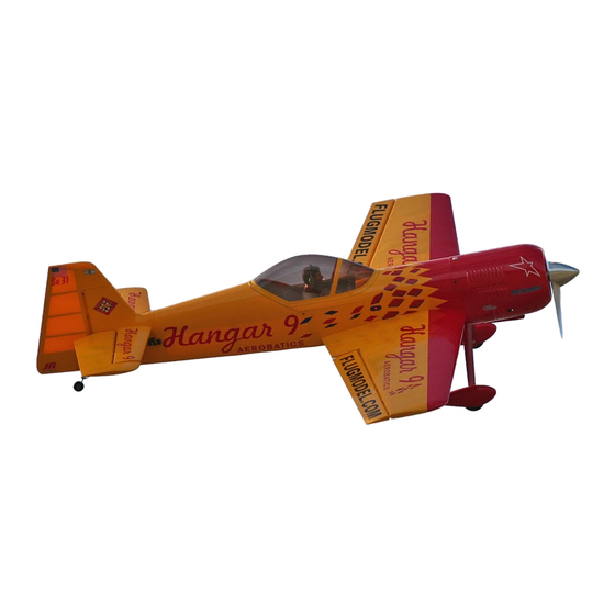
1/3-Scale Unlimited Aerobatic ARF
INSTRUCTION MANUAL
• Superior controllability and aerobatic flight characteristics
• Lightweight construction
• Designed by veteran TOC competitor Mike McConville
• 90% built 1/3-scale ARF
• Plug-in wings for easy transport and field assembly
Specifications
Wingspan: . . . . . . . . . . . . . . . . . . . . . . . . . . . . . . . . 97 in (2463.8 mm)
Length: . . . . . . . . . . . . . . . . . . . . . . . . . . . . . . . . . . . 88.7 in (2253 mm)
Wing Area: . . . . . . . . . . . . . . . . . . . . . . . . . . . 1810 sq in (116.7 sq dm)
Weight: . . . . . . . . . . . . . . . . . . . . . . . . . . . . 22.5–25.5 lb (10.2–11.6 kg)
Recommended Engines: . . . . . . . . . . . . . . . . . . . . . . . . . . . . . . 60–80cc
TM
®
WE GET PEOPLE FLYING
Advertisement
Table of Contents

Related Manuals for Hangar 9 Sukhoi SU-31


Summary of Contents for Hangar 9 Sukhoi SU-31
-
Page 1: Instruction Manual
® WE GET PEOPLE FLYING 1/3-Scale Unlimited Aerobatic ARF INSTRUCTION MANUAL • Superior controllability and aerobatic flight characteristics • Lightweight construction • Designed by veteran TOC competitor Mike McConville • 90% built 1/3-scale ARF • Plug-in wings for easy transport and field assembly Specifications Wingspan: . -
Page 3: Table Of Contents
Table of Contents Introduction ..................4 Warning . -
Page 4: Introduction
JR 8231 servos with excellent results. A less powerful servo can lead to a crash. Horizon Hobby, Inc. 4105 Fieldstone Road The 1/3-Scale Sukhoi Su-31 does not include hardware. Many Champaign, IL 61822 experienced giant scale pilots have specific hardware preferences (217) 355-9511 and can individually choose the components they prefer. -
Page 5: Additional Required Equipment
Additional Required Equipment Radio Equipment with Computer Radio 1000mAh receiver battery pack or larger Servos with 80 oz in of torque minimum (elevator and rudder) (JR8101, 4721, 2721, or 8411 or equivalent) (4) Servos with 60 oz in of torque (aileron) (4) Servo for throttle (standard) (1) Y-Harness (JRP133) (2) 24"... -
Page 6: Other Items Needed (Not Included In The Kit)
Other Items Needed (not included in the kit) ® Zenoah Gas Start Kit (ZEN20002) Includes: • Kill Switch (ZEN20000) • Mixing Cup (HAN3101) • Oil (2-cycle) (ZEN20001) • Gas Stopper (DUB400) • Fuel Filler (HAN115) • 3' Fuel Line (DUB799) •... -
Page 7: Contents Of Kit
Fiberglass Painted Cowl (HAN1284) Left Horizontal Stabilizer and Elevator (HAN1280) Landing Gear (HAN1285) Rudder (HAN1281) Wheelpants (HAN1286) Wing Tube (HAN1256) Included in the optional Hangar 9 ® 1/3-Scale Hardware Package HAN1220—JR Tail Wheel Assembly with Hardware (OHI130) HAN1221—Futaba 4-40 Ball Links (DLR87) (9) 8-32 Swivel Control Horns (DLR01B) (8) "... -
Page 8: Installing The Wing To The Fuselage
Section 1: Installing the Wing to the Fuselage Parts Needed • Left wing panel w/aileron attached (taped in place) • Right wing panel w/aileron attached (taped in place) • Fuselage • Wing Tube • 1/4" x 20 bolt with washer (2) Tools and Adhesives Needed •... -
Page 9: Section 2: Installing The Aileron Servos
All servos will have a slightly different leads to exit the root of the wing. neutral. If you are using Hangar 9 metal arms, they don’t all orient the same, (i.e., the splines are not oriented the same relative to the arm). - Page 10 Note: A computer radio using flapperon mixing is recommended. Step 5. With the servos in position, mark the four locations for In this case, each wings servos plug into a Y-harness and the mounting screws. Remove the servo and drill a 1/16" pilot then the Y-harnesses are plugged directly into the receiver hole in the servo rails.
-
Page 11: Section 3: Installing The Aileron Control Horns
Section 3: Installing the Aileron Control Horns Parts Needed Step 3. Measure 1/4" rearward from the marks above 90 degees to the hinge line and make another mark using a pen. This is the • Left and Right wings w/ailerons position for the control horn. - Page 12 Step 5. Carefully counter sink the holes on the top of the Step 7. Screw the A-nuts in place as shown. Allow the epoxy to aileron with a #8 counter sink. Use an 8-32 tap to tap the holes fully cure. in the aileron.
-
Page 13: Section 4: Hinging And Sealing The Aileron Control Surfaces
It’s important to control. The Hangar 9 1/3-Scale Sukhoi control surfaces are frequently mix afresh batch of 30-minute epoxy in predrilled to use Robart Super Hinge Points (ROB309). - Page 14 Step 4. Mix 1 ounce of 30-minute epoxy. Using a syringe or Step 6 photo toothpick, place a sufficient amount of epoxy in each of the hinge pockets in one aileron half. Step 7. When the epoxy has fully cured, move each control surface throughout its travel range several times to break away any epoxy in the hinge.
- Page 15 Step 9. Using a ruler, measure 1/2" from the folded crease and Step 12. Remove the backing from one piece of the UltraCote. mark the pieces with a pen. Place the folded crease side to the center of the hinge line on the bottom of one wing half.
-
Page 16: Section 5: Installing The Aileron Linkages
Pro-Link to lengthen or shorten the linkage. Tools and Adhesives neede Hangar 9 also offers a Pro-Link Wrench (HAN3558) to • Screwdriver (small) make adjustments easier. • Threadlocker •... - Page 17 Step 4. Temporarily plug the servos into the receiver and set Step 6. Deflect the ailerons stick to full right. Hold it there (the the programming to get the aileron functioning correctly. Center easiest way is to have your transmitter set to PCM: hold and the control surface with the trailing edge of the wing.
-
Page 18: Section 6: Installing The Rudder And Elevator Servos
80 oz in of servo torque. Using servos with less torque could Note: If using a non-computer radio, install one of the cause a crash. In the prototype 1/3-Scale Sukhoi Su-31, we used servos with the Y-harness attached in the top opening JR8101 and JR8411 servos with excellent results. -
Page 19: Installing The Elevator, Control Horns, And Linkages
Section 7: Installing the Elevator, Control Horns, and Linkages Parts Needed Step 2. The hole for the control horn is drilled at 90 degrees to the centerline of the elevator as shown in the illustration below. • Right and left stabilizers w/elevators Drill strait through the elevators using the bit included with the •... - Page 20 Step 4. Mix a small amount of 30-minute epoxy and lightly coat the inside of the tapped holes and the 8-32 x 2" screws. From the top of the elevator, install the 8-32 x 2" screw into the tapped holes and securely tighten. Wipe away any excess epoxy with rubbing alcohol and a paper towel.
- Page 21 Step 8. Insert the shorter of the tail tubes into the forward hole Step 11. Install the molded swivel clevis onto the control horn in the rear of the fuselage. Insert the longer of the tail tubes into screws until the bottom of the clevis is 5/8" from the elevator. the rear hole in one of the stabilizers halves then into the rear hole of the fuselage and slide it onto the smaller tube in the fuselage until it touches the side of the fuselage.
-
Page 22: Installing The Rudder, Control Horns, And Linkages
Section 8: Installing the Rudder, Control Horns, and Linkages Parts Needed Step 3. Using an 8-32 tap, thread the hole you just drilled in the rudder. • Rudder • Fuselage • Control Horn (DLRO1B) (2) • 4-40 Ball Links (DLR87) (2) •... - Page 23 Step 6. Thread an A-nut (included with swivel clevis) onto each Step 8. Hinge the rudder using the same techniques as with the side of the threaded rod and securely tighten against the rudder. aileron and elevator. Note: You may need to drill out the bottom hinge location in the rudder using a 5/32"...
-
Page 24: Section 9: Attaching The Tail Wheel
Section 9: Attaching the Tail Wheel Parts Needed Step 3. Drill 7/64" pilot holes at the previously marked positions. • Fuselage assembly • Ohio Superstar Large Tail Wheel Assembly (#OHI130) • #6 x 3/4" button head screws (DUB351) (not included) (2) Tools and Adhesives Needed •... -
Page 25: Installing The Landing Gear And Wheelpants
Section 10: Installing the Landing Gear and Wheelpants Parts Needed Step 2. Place a wheel centered in the wheelpant and mark the edge of the wheelpant at the axle hole. Mark the position on both • Fuselage wheelpants with a felt-tipped pen, being sure to mark the same •... - Page 26 Step 4. Make a 1/2" hole at the marked position on the wheelpants. Step 6. Remove the wheelpants and carefully drill a 9/64" hole It may be easier to drill a smaller hole first, then progressively through the wheelpants at the mark made in the previous step. increasing to a larger bit size finishing up with a Moto-tool.
- Page 27 Step 9. Secure the wheelpants in place using 4-40 x 1/2" Step 11. Remove the landing gear hatch and mount the landing screws with washer and split washer through the landing gear gear to the fuselage using four 10-32 x 1" bolts and locking nuts. and into the blind nut in the wheelpants.
-
Page 28: Installing The Receiver, Battery, And Fuel Tank
Section 11: Installing the Receiver, Battery, and Fuel Tank Parts Needed Step 3. Securely attach the battery to the battery tray. Be sure to place RC foam under the battery to isolate vibration. • Fuselage assembly • 1400mAh or larger battery pack •... - Page 29 Step 6. Mount the receiver switch in a convenient location in Step 7. Assemble the tank per the instructions included with the the side of the fuselage. tank. Mount the gas tank just ahead of the wing tube close to the center of gravity.
-
Page 30: Mounting The Engine And Cowl
Zenoah GT-80 gasoline engine. We at Step 1. Fit the engine to the firewall using four 1/4"-20 x 1/2" Hangar 9 understand that you may be tempted to use one of the socket head screws, split washers, and blind nuts provided. - Page 31 Step 4. Use a 4-40 rod with a ball link to attach to the engines Step 2. Install the adaptor plate and engine to the firewall choke lever. Attach the ball link to the choke lever using a 4-40 using 1/4-20 x 1 "...
- Page 32 Step 5. Run the fuel lines from the pick up in the tank to the Step 7. Temporarily install the canopy hatch and trial fit the carburetor and run the vent line out the bottom of the firewall. Sukhoi cowl in place. Mark the location of the four mounting We recommend using a fuel filler and a kill switch mounted on screws and use a 1/8"...
-
Page 33: Section 13: Hatch Assembly
Section 13: Hatch Assembly Parts Needed Step 3. Install a 1/3-scale pilot figure to the canopy hatch using Shoe Goo or a similar adhesive that will remain flexible. Let the • Hatch glue dry before securing the canopy in place. •... -
Page 34: Section 14: Balancing The Model
A 7-channel or greater computer radio is highly recommended plug into channel 6. With flapperon activated in the programming, for the Hangar 9 1/3-Scale Sukhoi SU-31. This allows the this allows for independent travel adjustment of each aileron in following features: each direction and electronic aileron differential. -
Page 35: Control Throws
Section 16: Control Throws Recommended Control Throws Standard Rate 3-D Rate Aileron 20 degrees up 35 degrees up 20 degrees down 35 degrees down Elevator 12 degrees up 38 to 40 degrees up 14 degrees down 38 to 40 degrees down Rudder 28 degrees left-right 40 degrees left-right... -
Page 36: Setup And Flight Information By Mike Mcconville
Section 18: Setup and Flight Information by Mike McConville Our new 1/3-Scale Sukhoi will blow away almost any pilot wanting The Prototype Model Setup to fly aerobatics. When designing this model, I incorporated All of the recommended settings in this manual are a result of design features and enhancements that I used in several the flight-testing on the prototype Sukhois. - Page 37 Computer Radio Enhancements Rates and Expos: When andWhere to Use Them A computer radio will allow you to do quite a bit of fine-tuning of the feel of the Sukhoi, which will make aerobatics even easier. I always use expo to soften the feel of the model. On high 3-D Below are the programming enhancements I normally use to trim rates, I use quite a bit.
- Page 38 Sukhoi at Its Best The Blender 3-D maneuvers (in simplest terms) are maneuvers performed by an airplane that are not usually done in a normal airplane flight path. What can be done with a 3-D plane is to make it fly like no other.
- Page 39 • The Elevator • The Harrier What it is: The plane drops vertically while in a nose What it is: It is very slow forward flight in a very nose high attitude. Depending on the head wind conditions, the high (about 45°) attitude. model will drop anywhere from about a 45°...
- Page 40 • The Waterfall • The Torque Roll What it is: This maneuver is a continuous tail-over-nose What it is: The Sukhoi “hovers” vertically in place, descending flip. It is not a loop, but the aircraft actually rotating left around its roll axis. flops around its canopy.
- Page 41 • The Parachute • The Wall What it is: The Parachute is a vertical dive that instantly What it is: The Wall is a Parachute turned on end. The decelerates in its descent as it instantaneously corners model starts in normal level flight and suddenly corners into an Elevator.
-
Page 42: Ama Safety Code
AMA National Model Aircraft Safety Code Effective January 1, 2001 Model flying must be in accordance with this code in order for primary means of propulsion are limited to a maximum AMA Liability Protection to apply. weight of 3.3 pounds and a G series motor. (A model aircraft is defined as an aircraft with or without an engine, not able General to carry a human being.) - Page 44 © Copyright 2002, Horizon Hobby, Inc. (217) 355-9511...
Need help?
Do you have a question about the Sukhoi SU-31 and is the answer not in the manual?
Questions and answers