
Related Manuals for ADLINK Technology cPCI-6965 Series


Summary of Contents for ADLINK Technology cPCI-6965 Series
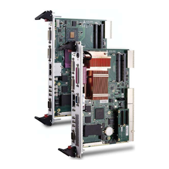
- Page 1 Series 6U CompactPCI Single Board Computer with Intel® Core™2 Duo, Celeron® M Processor User’s Manual Manual Rev. 2.00 Revision Date: April 27, 2009 Part No: 50-15068-1000 Advance Technologies; Automate the World.
-
Page 2: Revision History
Revision History Revision Release Date Description of Change(s) 2.00 2009/04/27 Initial Release... -
Page 3: Preface
Preface Copyright 2009 ADLINK Technology Inc. This document contains proprietary information protected by copy- right. All rights are reserved. No part of this manual may be repro- duced by any mechanical, electronic, or other means in any form without prior written permission of the manufacturer. - Page 4 Using this Manual Audience and Scope The cPCI-6965 User’s Manual is intended for hardware technicians and systems operators with knowledge of installing, configuring and operating industrial grade CompactPCI modules. Manual Organization This manual is organized as follows: Chapter 1, Overview: Introduces the cPCI-6965, its features, block diagrams, and package contents.
- Page 5 cPCI-6965 Conventions Take note of the following conventions used throughout this manual to make sure that users perform certain tasks and instructions properly. Additional information, aids, and tips that help users perform tasks. NOTE: NOTE: Information to prevent minor physical injury, component dam- age, data loss, and/or program corruption when trying to com- plete a task.
- Page 6 This page intentionally left blank. Preface...
-
Page 7: Table Of Contents
cPCI-6965 Table of Contents Revision History..............ii Preface ..................iii List of Tables................v List of Figures ............... vii 1 Overview ................1 Introduction ................1 Features................2 Block Diagram ..............3 Product List................4 SBC ................4 Rear Transition Module ..........4 Package Contents ............... - Page 8 DVI ..................20 Super I/O ................20 Battery ................20 PMC Site................20 Onboard USB Flash............21 4 Board Interfaces..............23 cPCI-6965 SBC Board Layout ........... 23 cPCI-6965 SBC Assembly Layout ........24 cPCI-6965 SBC Assembly Layout ........25 cPCI-6965, cPCI-6965D SBC Front Panel ......26 System LEDs ..............
- Page 9 cPCI-6965 7 Utilities ................65 Watchdog Timer ..............65 Using the Watchdog in an Application ......65 Sample Code ..............66 Preboot Execution Environment (PXE)......69 8 BIOS Setup Utility............. 71 Starting the BIOS............... 71 Setup Menu ..............72 Navigation ..............72 Hotkey Descriptions ............
- Page 10 Clear User Password ............ 92 Change Supervisor Password ........92 Change User Password ..........93 Chipset Setup ..............94 USB Functions .............. 94 USB 2.0 Controller ............94 HDA Controller .............. 94 Onboard LAN BIOS Init ..........95 Exit Menu ................96 Save Changes and Exit ..........
-
Page 11: List Of Tables
cPCI-6965 List of Tables Table 2-1: SBC I/O Connectivity ..........11 Table 2-2: RTM (4HP) I/O Connectivity ........12 Table 2-3: RTM (8HP) I/O Connectivity ........12 Table 2-4: CompactPCI input voltage characteristics ....13 Table 2-5: Power consumption of Intel® Core™2 Duo T7500 14 Table 2-6: Power consumption of Intel®... - Page 12 This page intentionally left blank. List of Tables...
-
Page 13: List Of Figures
Figure 4-1: cPCI-6965 Board Layout ......... 23 Figure 4-2: cPCI-6965 SBC Assembly Layout......24 Figure 4-3: cPCI-6965D SBC Assembly Layout ......25 Figure 4-4: cPCI-6965 Series Front Panel Layout ..... 26 Figure 4-5: cPCI-R6000-965, cPCI-R6000-L Board Layout..28 Figure 4-6: cPCI-R6000-965, cPCI-R6000-L Front Panel ..29 Figure 4-7: cPCI-R6000-965D, cPCI-R6000D-L Board Layout . - Page 14 This page intentionally left blank. viii List of Figures...
-
Page 15: Overview
Overview 1.1 Introduction The cPCI-6965 Series is a highly integrated 6U CompactPCI SBC in single slot (4HP) or dual slot (8HP) width form factor. It has been designed to support the Intel® Core™ 2 Duo and Celeron® M pro- cessors in 478-pin Micro-FCPGA. -
Page 16: Features
1.2 Features 6U CompactPCI SBC in 4HP or 8HP width form factor Single Core™ 2 Duo 2.2GHz processor, 4MB L2 cache Front Side Bus 800MHz Mobile Intel® GME965 Memory Controller Hub and ICH8M I/O Hub Dual Channel DDR2 unbuffered non-ECC SDRAM at 667MHz Two stacked SO-DIMM sockets for maximum up to 4GB memory... -
Page 17: Block Diagram
GbE 2 Intel ICH8M-DO 82573L PCI 32b/33M PCI 32b/33M SATA 2 2050B header BIOS USB 1/2/3/4 SATA 1 2.5” HDD COM x2 SATA 3, HD Audio, 5x USB, SMBus Parallel PCIEx4 IT8712F PS/2 KB/MS Figure 1-1: cPCI-6965 Series Block Diagram Overview... -
Page 18: Product List
1.4 Product List Products included in the cPCI-6965 Series include: cPCI-6965: 4HP (single-slot) width 6U CompactPCI featur- ing Core™2 Duo or Celeron® processor; 512MB, 1GB, 2GB or 4GB memory by SO-DIMM; CompactFlash slot, 2xSATA ports, and 4xUSB, 2xGbE, DVI-D, DVI-I, COM and... -
Page 19: Package Contents
Please obtain authorization before returning any prod- uct to ADLINK. The packing contents of the cPCI-6965 Series are non-standard configurations and may vary depending on customer requests. - Page 20 This product must be protected from static discharge and phys- ical shock. Never remove any of the components except at a static-free workstation. Use the anti-static bag shipped with the CAUTION: product when putting the board on a surface. Wear an anti-static wrist strap properly grounded on one of the system's ESD ground jacks when installing or servicing system compo- nents.
-
Page 21: Specifications
cPCI-6965 Specifications 2.1 cPCI-6965 SBC Specifications CompactPCI PICMG® 2.0 CompactPCI® Rev. 3.0 Standard PICMG® 2.1 Hot Swap specification Rev.2.0 Standard 6U CompactPCI® Board size: 233.23 mm x 160mm Single-slot (4HP, 20.32mm) or dual-slot (8HP, 40.64mm) Mechanical width CompactPCI® connectors with J1, J2, J4, J5 for cPCI-6965, cPCI-6965D CompactPCI®... - Page 22 2.5” SATA HDD direct connector onboard 7-pin SATA port on board Storage Interfaces CompactFlash Type II socket onboard USB NAND Flash module option BIOS AMI® Core 8 16Mbit SPI flash memory cPCI-6965 (4HP) 4x USB 2.0 ports 2x 10/100/1000BASE-T Ethernet ports DVI-I port (digital and analog) DVI-D port (digital only) DB-9 serial port...
- Page 23 cPCI-6965 Notes: 1. ADLINK-certified thermal design. The thermal performance is dependent on the chassis cooling design. Forced airflow with 16CFM is required. Temperature limit of optional mass storage devices may affect the thermal specification. 2. The hard drive limits the operational vibration. When applica- tion requires higher specification for anti-vibration, it is recom- mended to use flash disk such as CF or USB flash disk module.
-
Page 24: Cpci-R6000-965(D) & Cpci-R6000(D)-L
2.2 cPCI-R6000-965(D) & cPCI-R6000(D)-L Specifications Standard 6U CompactPCI® rear I/O Board size: 233.23 mm x 80mm Mechanical Single-slot (4HP, 20.32mm) or dual-slot (8HP, 40.64mm) width CompactPCI® connectors with rJ3 and rJ5 cPCI-R6000-965 (4HP) 2x USB 2.0 ports VGA port (via DVI dongle) External 68-pin SCSI connector cPCI-R6000-L (4HP) 2x USB 2.0 ports... -
Page 25: I/O Connectivity Table
cPCI-6965 2.3 I/O Connectivity Table cPCI-6965 cPCI-6965D Function Faceplate Board Faceplate Board Y x2 Y x2 Y (DB-9) Y x2 (DB-9) Y x4 Y x4 Y x2 Y x2 SATA Y x2 Y x2 PS/2 KB/MS Parallel USB Flash Y (optional) Y (optional) LEDs Y x4... -
Page 26: Table 2-2: Rtm (4Hp) I/O Connectivity
RTM (4HP) cPCI-R6000-965 cPCI-R6000-L Function Faceplate Board Faceplate Board Y x2 Y x2 SATA Y (7-pin) Y (7-pin) SCSI Floppy Table 2-2: RTM (4HP) I/O Connectivity RTM (8HP) cPCI-R6000-965D cPCI-R6000D-L Function Faceplate Board Faceplate Board Y x4 Y x4 SATA Y (7-pin) Y (7-pin) PS/2 KB/MS... -
Page 27: Power Requirements
cPCI-6965 2.4 Power Requirements In order to guarantee a stable functionality of the system, it is rec- ommended to provide more power than the system requires. An industrial power supply unit should be able to provide at least twice as much power as the entire system requires of each voltage. -
Page 28: Power Consumption
Power Consumption The following tables provide information on the power consump- tion of the cPCI-6965 Series when using the Intel® Core 2 Duo T7500 or Celeron 550 processor with 2x 2GB SO-DIMM and onboard 60GB SATA hard drive. The systems were tested in Idle Mode and Full Loading Mode under Windows XP. -
Page 29: Functional Description
Functional Description The following sections describe the cPCI-6965 Series features and functions. The following table lists the processors supported by the cPCI-6965 Series and their power ratings. Features Intel® Core™2 Duo T7500 Intel® Celeron® 550 Clock 2.2 GHz 2.0 GHz... -
Page 30: Intel® Core™2 Duo Processor T7500
Intel® Core™2 Duo Processor T7500 The Intel® Core™2 Duo T7500 processor is a high-performance, low-power processor based on the Intel® Core™ microarchitec- ture and 65-nm process technology. The Intel Core 2 Duo proces- sor supports the Mobile Intel® 965 Express Chipset and Intel® 82801HBM ICH8M Controller Hub Based Systems. -
Page 31: Intel® Celeron® Processor 550
cPCI-6965 Intel® Celeron® Processor 550 The following list provides some of the key features of this processor: Single core On-die, primary 32-KB instruction cache and 32-KB write-back data cache On-die, 1-MB second level shared cache with advanced transfer cache architecture 533-MHz source-synchronous front side bus (FSB) Supports Intel®... -
Page 32: Chipset
3.1 Chipset The cPCI-6965 Series incorporates the Mobile Intel® GME965 Memory Controller Hub (MCH) and ICH8 Mobile (ICH8M) I/O Con- troller Hub. Intel® GME965 Memory Controller Hub The following outlines the key features of GME965 MCH. Processor Support Intel® Core™2 Duo Mobile Processor for Mobile Intel 965... -
Page 33: Intel® Ich8 Mobile I/O Controller Hub
cPCI-6965 Integrated Graphics Mobile Intel® Graphics Media Accelerator X3100 (Mobile® Intel® GMA X3100) Supports a QXGA maximum resolution of 2048x1536 at 60Hz, 32-bpp reduced blanking timing (driver limited) Supports Analog TV-Out, LVDS, Analog CRT and SDVO (the cPCI-6965 implements analog CRT and SDVO only) Intel®... -
Page 34: Dvi
A Panasonic CR2032 is equipped on board by default. 3.5 PMC Site The cPCI-6965 series supports a PMC site for front panel I/O expansion. The PMC site provides a 32bit/33MHz PCI bus link from the Intel® ICH8M I/O Hub. The PMC site supports +3.3V and 5V signaling. -
Page 35: Onboard Usb Flash
cPCI-6965 3.6 Onboard USB Flash The cPCI-6965 provides a 9-pin header (CN7) to install a horizontal USB flash disk module. The following figure illus- trates an example of USB flash module layout. Max. 29mm Max. 39mm 27.3 ~ 27.9 mm Figure 3-1: USB Flash Disk Mechanical Layout USB Flash Disk Mechanical Layout Maximum space reserved for USB flash disk is 39mm x... - Page 36 This page intentionally left blank. Functional Description...
-
Page 37: Board Interfaces
Board Interfaces This chapter illustrates the board layout, connector pin assignments, and jumper settings to familiarize users with the cPCI-6965 Series. 4.1 cPCI-6965 SBC Board Layout CN10-12 CN15 CN13 CN14 SODIMM CPU socket CN3/5 7-pin SATA connector North Bridge Intel® GME965... -
Page 38: Cpci-6965 Sbc Assembly Layout
4.2 cPCI-6965 SBC Assembly Layout This section describes the final assembly layout of cPCI-6965 (4HP). Heatsink 2.5” SATA HDD USB flash disk DDR2 SODIMM modules DB-6910SAT Figure 4-2: cPCI-6965 SBC Assembly Layout Board Interfaces... -
Page 39: Cpci-6965 Sbc Assembly Layout
cPCI-6965 4.3 cPCI-6965 SBC Assembly Layout This section describes the final assembly layout of cPCI-6965D (8HP). The dual-slot width cPCI-6965D is comprised of the cPCI- 6965 single-slot main board and the DB-6965PMC riser card (Upper1 and Upper2 are the PMC connectors). Card Heatsink USB flash disk... -
Page 40: Cpci-6965, Cpci-6965D Sbc Front Panel
4.4 cPCI-6965, cPCI-6965D SBC Front Panel cPCI-6965 USB x4 COM2 DVI-I DVI-D GbE 1/2 cPCI-6965D PS/2 Printer port COM1 DVI-I DVI-D USB x4 COM2 GbE 1/2 Figure 4-4: cPCI-6965 Series Front Panel Layout Board Interfaces... -
Page 41: System Leds
cPCI-6965 System LEDs Color Condition Indication System is off Power Green (PW) System is on General Purpose Blue Reserved for user definition PW GP (GP) No Watchdog event Amber (WDT) Watchdog event alert No read/write access to HDD HDD is installed (HD) Blink Data read/write in process... -
Page 42: Cpci-R6000-965/R6000-L Rtm Board Layout
4.5 cPCI-R6000-965/R6000-L RTM Board Layout cPCI-R6000-965 cPCI-R6000-L CNY1-R CNY1-R U26-R CN16-R CN16-R CN15-R CN15-R CN14-R CN14-R CN1-R CN1-R U31-R CN12-R CN5-R U26-R PCI-E to PCI bridge CN12-R External SCSI connector U31-R SCSI controller CN15/16-R USB ports CN1-R SATA port (7-pin) CNY1-R DVI to VGA adapter CN5-R... -
Page 43: Cpci-R6000-965/R6000-L Rtm Front Panel
cPCI-6965 4.6 cPCI-R6000-965/R6000-L RTM Front Panel cPCI-R6000-965 SCSI USB x2 cPCI-R6000-L Figure 4-6: cPCI-R6000-965, cPCI-R6000-L Front Panel Board Interfaces... -
Page 44: Cpci-R6000-965D/6000D-L Rtm Board Layout
4.7 cPCI-R6000-965D/6000D-L RTM Board Layout cPCI-R6000-965D cPCI-R6000D-L CN19-R CN18-R CN11-R CN1-R CN1-R U31-R CN12-R CN5-R CN18/19-R USB ports CN12-R External SCSI connector CN11-R PS/2 KB/MS port CN5-R Internal SCSI connector CN1-R SATA port (7-pin) U31-R SCSI controller Mic-in Line-out Figure 4-7: cPCI-R6000-965D, cPCI-R6000D-L Board Layout Board Interfaces... -
Page 45: Cpci-R6000-965D/R6000D-L Rtm Front Panel
cPCI-6965 4.8 cPCI-R6000-965D/R6000D-L RTM Front Panel Line-out PS/2 KB/MS cPCI-R6000-965D Mic-in SCSI USB x2 USB x2 Line-out PS/2 KB/MS cPCI-R6000D-L Mic-in Figure 4-8: cPCI-R6000-965D, cPCI-R6000D-L Front Panel Board Interfaces... -
Page 46: Connector Pin Assignments
4.9 Connector Pin Assignments USB Connectors (CN9-12) Pin # Signal Name UV0- UV0+ Table 4-2: USB Connector Pin Definition PS/2 Keyboard/Mouse Connector Pin # Signal Function KBDATA Keyboard Data MSDATA Mouse Data Ground Power KBCLK Keyboard Clock MSCLK Mouse Clock Table 4-3: PS/2 Keyboard/Mouse Connector Pin Definition Board Interfaces... -
Page 47: Table 4-4: Dvi-D Connector Pin Definition
cPCI-6965 DVI-I Connector (CN2) Pin # Signal Pin # Signal TMDS Data2- Hot Plug Detect TMDS Data2+ TMDS Data0- TMDS Data2/4 Shield TMDSData0+ TMDS Data4- TMDS Data0/5 Shield TMDS Data4+ TMDS Data5- DDC Clock [SCL] TMDS Data5+ DDC Data [SDA] TMDS Clock Shield Analog vertical sync TMDS Clock +... -
Page 48: Table 4-5: Dvi-D Connector Pin Definition
DVI-D Connector (CN4) Pin # Signal Pin # Signal TMDS Data2- TMDS Data3+ TMDS Data2+ +5 V Power TMDS Data2/4 Shield TMDS Data4- Hot Plug Detect TMDS Data4+ TMDS Data0- DDC Clock [SCL] TMDSData0+ DDC Data [SDA] TMDS Data0/5 Shield Analog vertical sync TMDS Data5- TMDS Data1-... -
Page 49: Table 4-7: Parallel Port Connector Pin Definition
cPCI-6965 Parallel Port Pin # Signal Name Pin # Signal Name STROBE AUTO FEED DATA0 ERROR DATA1 INIT DATA2 SELECT IN DATA3 DATA4 DATA5 DATA6 DATA7 ACKNOWLEDGE BUSY PAPER EMPTY SELECT Table 4-7: Parallel Port Connector Pin Definition Board Interfaces... -
Page 50: Table 4-8: Gbe Connector Pin Definitions
RJ-45 Gigabit Ethernet Connectors (GbE1-2) Pin # Signal Name Function LANB_TX0P Media Dependent Interface 1+ LANB_TX0N Media Dependent Interface 1- LANB_TX1P Media Dependent Interface 2+ LANB_TX1N Media Dependent Interface 2- LANB_TX2P Media Dependent Interface 3+ LANB_TX2N Media Dependent Interface 3- LANB_TX3P Media Dependent Interface 4+ LANB_TX3N... -
Page 51: Table 4-10: Sata Connector Pin Definition
cPCI-6965 Serial ATA Connectors (CN7, CN4-R) Pin # Signal Table 4-10: SATA Connector Pin Definition Serial ATA Connector on DB-6910SAT Pin # Signal Signal Power Reserved P13~P15 Table 4-11: DB-6910SAT SATA Connector Pin Definition Board Interfaces... -
Page 52: Table 4-12: Compactflash Connector Pin Definition
CompactFlash Connector (CN13) Signal Name Pin# Pin# Signal Name DD11 DD12 DD13 DD14 DD15 CS1J CS3J SDIORJ SDIOWJ IRQ15 PCSEL BRSTDRVJ SDIORDY SDACKJ IDEACTJ DIAG IOIS16J DD10 Table 4-12: CompactFlash Connector Pin Definition Board Interfaces... - Page 53 cPCI-6965 PMC Connector (Upper1, Upper2) Pin# Upper1 Signal Upper2 Signal PMC_TCK +12V -12V TRST# INTA# INTB# INTC# MOD1# INTD# MODE2# +3V3 +3.3V CLK33 RST2# MODE3# +3.3V GNT3# MOD4# REQ3# PME# AD30 AD31 AD29 AD28 AD27 AD26 AD25 AD24 +3.3V IDSEL CBE3# AD23 AD22...
-
Page 54: Table 4-13: Pmc Connector Pin Definition
Pin# Upper1 Signal Upper2 Signal TRDY# IRDY# +3.3V DEVSEL# STOP# PCIXCAP PERR# LOCK-L +3.3V SERR# CBE1# AD14 AD15 AD13 AD12 M66EN AD11 AD10 +3.3V CBE0# +3.3 ACK64# +3.3V REQ64# Table 4-13: PMC Connector Pin Definition Board Interfaces... -
Page 55: Table 4-14: Compactpci J1 Connector Pin Definition
cPCI-6965 CompactPCI J1 Connector Pin Assignment TRST# TCK# TMS# TDI# IRQA# IRQB# IRQC# IRQD# +5V_IPMB HEALTHY# RESET# GNT0# REQ0# CLK0 AD31 AD30 AD29 AD28 AD27 AD26 AD25 AD24 CBE3# AD23 AD22 AD21 AD20 AD19 AD18 AD17 AD16 CBE2# 12-14 FRAME# IRDY# TRDY# DEVSEL#... -
Page 56: Table 4-15: Compactpci J2 Connector Pin Definition
CompactPCI J2 Connector Pin Assignment CLK1 REQ1# GNT1# REQ2# CLK2 CLK3 SYSEN# CGNT2# REQ3# CLK4 GNT3# REQ4# GNT4# Pull up Pull up Pull up Pull up Pull up Pull up Pull up Pull up Pull up Pull up Pull up Pull up Pull up Pull up... -
Page 57: Table 4-16: Compactpci J3 Connector Pin Definition
cPCI-6965 CompactPCI J3 Pin Assignment Pin Z 1 GND HDA_RST-L HDA_SYNC HDA_BIT_CLK HDA_SDOUT HAD_SDIN0 GND 2 GND HAD_SDIN1 HAD_SDIN2 HAD_SDIN3 3 GND PS2-KBD PS2-KBC PS2-MSD PS2-MSC 4 GND SATA-T2P SATA-T2N 5 GND 6 GND SATA-R2P SATA-R2N 7 GND I2C_CLK I2C_DAT 8 GND 9 GND RGB-BLUE... -
Page 58: Table 4-17: Compactpci J5 Connector Pin Definition
CompactPCI J5 Pin Assignment PCIE-TX0+ PCIE-TX0- PCIE-RX0+ PCIE-RX0- PCIE-TX1+ PCIE-TX1- PCIE-RX1+ PCIE-RX1- PCIE-TX2+ PCIE-TX2- PCIE-RX2+ PCIE-RX2- PCIE-TX3+ PCIE-TX3- PCIE-RX3+ PCIERX3- CLK0+ CLK0- RESET# GPIO0 GPIO1 GPIO2 GPIO3 GPIO4 MTR0# INDEX# GPIO6 FDEDIN# DENSEL# DIR# GPIO7 DSEL0# TRK0# WGATE# GPIO9 WDATA# STEP# DSKCHG# HDSEL#... -
Page 59: Switch And Jumper Settings
cPCI-6965 4.10 Switch and Jumper Settings COM1 Mode Selection Switches (SW1~SW4) This is switch is to select COM1 to be RS-232 full modem or RS-422, RS-485, RS-485+ half Duplex mode. RS-232 full modem is set by default. Location RS-232 Full Modem RS-422 Half Duplex RS-485... -
Page 60: Table 4-19: Com2 Mode Switch Settings
COM2 Mode Selection Switches (SW5~SW8) This is switch is to select COM2 to be RS-232 full modem or RS-422, RS-485, RS-485+ half Duplex mode. RS-232 full modem is set by default. Location RS-232 Full Modem RS-422 Half Duplex RS-485 Half Duplex RS-485+ Half Duplex Table 4-19: COM2 Mode Switch Settings... -
Page 61: Table 4-20: Pmc V(I/O) Select Jumper Settings
Clear CMOS Switch (SW9) The cPCI-6965 series comes with a Clear CMOS switch to reset the CMOS values to default. Press the Switch SW9 located near the J1 connector to clear the CMOS. PMC V(I/O) Select Jumper (JPX1) JPX1 is a three pin jumper for +3.3V or 5V PMC VIO signaling selection. - Page 62 This page intentionally left blank. Board Interfaces...
-
Page 63: Getting Started
RTM installation to chassis 5.1 CPU and Heatsink The cPCI-6965 Series comes with CPU and heatsink pre-installed. Uninstalling the heatsink is not recommended. If it is necessary to do so, please check that the thermal pad is not damaged before you re-install the heatsink to the board. -
Page 64: Memory Module Installation
5.2 Memory Module Installation The cPCI-6965 Series supports DDR2-667 unbuffered non-ECC memory modules via two stacked-type SO-DIMM sockets. The SO-DIMM modules have a 200-pin footprint and are notched to facilitate correct installation in the SO-DIMM sockets. At lease one memory module will be pre-installed in the lower socket. -
Page 65: Compactflash Card Installation
cPCI-6965 5.3 CompactFlash Card Installation 1. Remove the card retaining bracket from board by removing the two screws as shown. 2. Insert the CF card into the CF slot, then replace the card retaining bracket to prevent the CF card from sliding out of the slot. -
Page 66: Hard Drive Installation
5.4 Hard Drive Installation The cPCI-6965 Series provides space to install a slim type 2.5” Serial-ATA hard drive and comes with the required installation hardware. The HDD adapter kit includes screws, standoffs and SATA adapter board (DB-6910SAT). 1. Attach the four standoffs provided with the HDD adapter kit onto the SATA hard drive as shown below. - Page 67 cPCI-6965 3. Position the hard drive assembly on the cPCI-6965 so that the standoffs on the hard drive align with the screw holes on the board, and the connector on the DB-6910SAT adapter board is aligned with the board-to-board connector (CN14). 4.
- Page 68 5. Secure the hard drive with four screws from the board’s solder side. When removing the hard drive, be careful to grasp the adapter board and lift upwards in a vertical motion to disconnect it from the board-to-board connector. This will avoid damaging the CAUTION: adapter board and connectors.
-
Page 69: Pci Mezzanine Card (Pmc) Installation
cPCI-6965 5.5 PCI Mezzanine Card (PMC) Installation The PMC slot is designed to support 3.3V and 5V V(I/O), and the default setting is 3.3V. Before you install the PMC module on the cPCI-6965, please make sure that the PMC V(I/O) jumper JPX1 has been correctly set (see “PMC V(I/O) Select Jumper (JPX1)”... - Page 70 3. Secure the standoffs provided in the package to the PMC assembly as shown. 4. Remove the two PMC brackets and PMC faceplate from the front panel. Getting Started...
- Page 71 cPCI-6965 5. Secure the two PMC brackets to the both sides of the PMC front panel. 6. Align the male PMC connectors of the DB-6965PMC adapter board (component-side down) to the female PMC connectors of the host board and press down. Getting Started...
- Page 72 7. Secure the PMC assembly to the host board with the six screws provided as shown. Getting Started...
-
Page 73: Usb Flash Disk Module Installation
5.6 USB Flash Disk Module Installation The cPCI-6965 Series supports an onboard USB Flash Disk mod- ule via the CN5 pin header connector. To install a USB Flash Disk, follow the procedure below. 1. Secure the standoff to the underside of the USB module with the screw provided. -
Page 74: Installing The Cpci-6965 To The Chassis
5.7 Installing the cPCI-6965 to the Chassis The cPCI-6965 may be installed in a system or peripheral slot of a 6U CompactPCI chassis. These instructions are for reference only. Refer to the user guide that comes with the chassis for more information. -
Page 75: Rtm Installation
RTMs. Refer to previous sections for peripheral connectivity of all I/O ports on the RTM. When installing the cPCI-6965 Series and related RTMs, make sure the RTM is the correct matching model. You must install the correct RTM to enable functions (I/O inter- faces) on the rear panel. - Page 76 This page intentionally left blank. Getting Started...
-
Page 77: Driver Installation
cPCI-6965 Driver Installation 6.1 Chipset Drivers The cPCI-6965 drivers are available from the ADLINK All-In-One CD at X:\cPCI\cPCI-6965\, or from the ADLINK website (http://www.adlinktech.com). The following describes the driver installation procedures for Windows® XP. 1. Install the Windows operating system before installing any driver. -
Page 78: Scsi Driver
6.2 SCSI Driver The SCSI driver is available from the ADLINK All-In-One CD at X:cPCI\cPCI-6920\SCSI from ADLINK website (http://www.adlinktech.com) and the installation procedure for Windows XP is described below. 1. Click Start, right-click on My Computer, then select Properties from the drop-down menu. 2. -
Page 79: Utilities
cPCI-6965 Utilities 7.1 Watchdog Timer This section describes the operation of the cPCI-6965’s watchdog timer (WDT). The primary function of the WDT is to monitor the cPCI-6965's operation and to reset the system if a software appli- cation fails to function as programmed. The following WDT func- tions may be controlled using a software application: enabling and disabling reloading timeout value... -
Page 80: Sample Code
Sample Code The sample program written in C shown below offers an interactive way to test the Watchdog Timer under DOS. #include<stdio.h> #include<dos.h> static unsigned int IT8712_ioPort = 0x2e; void Enter_IT8712_Config(unsigned int flag) if(flag) IT8712_ioPort = 0x4e; else IT8712_ioPort = 0x2e; switch(IT8712_ioPort) case 0x2E: //Address port = 0x2E, enter keys = 0x87, 0x01, 0x55, 0x55... - Page 81 cPCI-6965 void Get_IT8712_ID(unsigned int &ID1, unsigned int &ID2) outportb(IT8712_ioPort, 0x20); ID1 = inportb(IT8712_ioPort+1); outportb(IT8712_ioPort, 0x21); ID2 = inportb(IT8712_ioPort+1); void IT8712_WDTRun(unsigned int count_value) unsigned int tempCount, registerValue; outportb(IT8712_ioPort, 0x07); outportb(IT8712_ioPort+1, 0x07);// Device 7 if(count_value >= 60) outportb(IT8712_ioPort, 0x72); registerValue = inportb(IT8712_ioPort+1); registerValue &= 0x7f;...
- Page 82 printf("WDT timeout in %d seconds.\n", tempCount); registerValue |= 0x40; //Enable WDT output through KBRST else printf("WDT is Disabled.\n"); registerValue &= 0xbf; //Disable WDT output through KBRST outportb(IT8712_ioPort+1, registerValue); // set WDT count is second outportb(IT8712_ioPort, 0x71); registerValue = inportb(IT8712_ioPort + 1); registerValue |= 0x60;// set Mouse &...
-
Page 83: Preboot Execution Environment (Pxe)
7.2 Preboot Execution Environment (PXE) The cPCI-6965 series supports the Intel® Preboot Execution Envi- ronment (PXE) that is capable of booting up or executing an OS installation through an Ethernet ports. To use PXE, there must be a DHCP server on the network with one or more servers running PXE and MTFTP services. - Page 84 This page intentionally left blank. Utilities...
-
Page 85: Bios Setup Utility
cPCI-6965 BIOS Setup Utility The following chapter describes basic navigation for the AMIBIOS®8 BIOS setup utility. 8.1 Starting the BIOS To enter the setup screen, follow these steps: 1. Power on the motherboard 2. Press the < Delete > key on your keyboard when you see the following text prompt: <... -
Page 86: Setup Menu
Setup Menu The main BIOS setup menu is the first screen that you can navi- gate. Each main BIOS setup menu option is described in this user’s guide. The Main BIOS setup menu screen has two main frames. The left frame displays all the options that can be configured. -
Page 87: Hotkey Descriptions
cPCI-6965 These keys include < F1 >, < F10 >, < Enter >, < ESC >, < Arrow > keys, and so on. . Note: There is a hot key legend located in the right frame on most setup screens. The <... - Page 88 The < F10 > key allows you to save any changes you have made and exit Setup. Press the < F10 > key to save your changes. The following screen will appear: Press the < Enter > key to save the configuration and exit. You can also use the <...
-
Page 89: Main Setup
cPCI-6965 8.2 Main Setup When you first enter the Setup Utility, you will enter the Main setup screen. You can always return to the Main setup screen by select- ing the Main tab. There are two Main Setup options. They are described in this section. -
Page 90: Advanced Bios Setup
8.3 Advanced BIOS Setup Select the Advanced tab from the setup screen to enter the Advanced BIOS Setup screen. You can select any of the items in the left frame of the screen, such as SuperIO Configuration, to go to the sub menu for that item. You can display an Advanced BIOS Setup option by highlighting it using the <... - Page 91 cPCI-6965 ing pages. An example of the CPU Configuration screen is shown below. Intel(R) Virtualization Tech Intel Virtualization Technology is a set of platform features that support virtualization of platform hardware and multiple soft- ware environmentss. When enabled, it offers data center man- agers the ability to consolidate multiple workloads on one physical server system.
-
Page 92: Ide Configuration
in decreased average power consumption and decreased average heat production. Intel® C-STATE Tech This option allows you to enable or disabled Intel C-STATE function. IDE Configuration You can use this screen to select options for the IDE Configuration Settings. Use the up and down < Arrow > keys to select an item. Use the <... -
Page 93: Floppy Configuration
cPCI-6965 Legacy IDE Channels When running in Compatible mode, SATA channels can be configured as a legacy IDE channels. Use this option to elect the location of the IDE channel. IDE Master/Slave Select one of the hard disk drives to configure it. Press <... -
Page 94: Super Io Configuration
Super IO Configuration You can use this screen to select options for the Super IO settings. Use the up and down < Arrow > keys to select an item. Use the < + > and < - > keys to change the value of the selected option. The settings are described on the following pages. - Page 95 cPCI-6965 if Serial Port1 uses 3F8/IRQ4, the option, the 3F8/IRQ4 will not appear in the options of Serial Port2. Parallel Port Address This option specifies the base I/O port address of the parallel port. Parallel Port Mode This option specifies the parallel port mode. Normal: Set this value to allow the standard parallel port mode to be used.
-
Page 96: Hardware Health Configuration
Hardware Health Configuration This option displays the current status of all of the monitored hard- ware devices/components such as voltages and temperatures. The options are Enabled and Disabled. BIOS Setup Utility... -
Page 97: Remote Access Configuration
cPCI-6965 Remote Access Configuration Remote access configuration provides the settings to allow remote access by another computer to get POST messages and send commands through serial port access. Remote Access Select this option to Enable or Disable the BIOS remote access feature. - Page 98 If you have changed the resource assignment of the serial ports in Advanced> SuperIO Configuration, you must Save Changes and Exit, reboot the system, and enter the setup menu again in order to NOTE: NOTE: see those changes reflected in the available Remote Access options. Serial Port Mode Select the baud rate you want the serial port to use for console redirection.
-
Page 99: Usb Configuration
cPCI-6965 USB Configuration You can use this screen to select options for the USB Configura- tion. Use the up and down < Arrow > keys to select an item. Use the < + > and < - > keys to change the value of the selected option. - Page 100 Enabled: Set this value to allow the use of USB devices during boot and while using DOS. Auto: This option auto detects USB Keyboards or Mice and if found, allows them to be utilized during boot and while using DOS. USB 2.0 Controller Mode The USB 2.0 Controller Mode configures the data rate of the USB port.
-
Page 101: Advanced Pci/Pnp Settings
cPCI-6965 8.4 Advanced PCI/PnP Settings Select the PCI/PnP tab from the setup screen to enter the Plug and Play BIOS Setup screen. You can display a Plug and Play BIOS Setup option by highlighting it using the < Arrow > keys. The Plug and Play BIOS Setup screen is shown below. -
Page 102: Boot Settings
8.5 Boot Settings Select the Boot tab from the setup screen to enter the Boot BIOS Setup screen. You can select any of the items in the left frame of the screen, such as Boot Device Priority, to go to the sub menu for that item. -
Page 103: Boot Settings Configuration
cPCI-6965 Boot Settings Configuration Use this screen to select options for the Boot Settings Configura- tion. Use the up and down <Arrow> keys to select an item. Use the <Plus> and <Minus> keys to change the value of the selected option. -
Page 104: Boot Device Priority
Boot Device Priority The items allow you to set the sequence of boot devices where BIOS attempts to load the disk operating system. First press <Enter> to enter the sub-menu. Then you may use the arrow keys to select the desired device, then press <+>, <-> or <PageUp>, <PageDown>... -
Page 105: Security Setup
cPCI-6965 8.6 Security Setup Password Support Two Levels of Password Protection Provides both a Supervisor and a User password. If you use both passwords, the Supervisor password must be set first. The system can be configured so that all users must enter a password every time the system boots or when Setup is exe- cuted, using either or either the Supervisor password or User password. -
Page 106: Supervisor Password
Remember the Password Keep a record of the new password when the password is changed. If you forget the password, you must erase the sys- tem configuration information in NVRAM. To access the sub menu for the following items, select the item and press <... -
Page 107: Change User Password
cPCI-6965 and press < Enter >. If the password confirmation is incorrect, an error message appears. The password is stored in NVRAM after completes. Change User Password Select Change User Password from the Security Setup menu and press < Enter >. Enter New Password: Type the password and press <... -
Page 108: Chipset Setup
8.7 Chipset Setup Select the Chipset tab from the setup screen to enter the Chipset BIOS Setup screen. You can select any of the items in the left frame of the screen to go to the sub menu for that item. The Chipset BIOS Setup screen is shown below. -
Page 109: Onboard Lan Bios Init
cPCI-6965 Onboard LAN BIOS Init Set this value to enable/disable the invoking of onboard LAN’s PXE ROM. Disabling can shorten the POST time by not initializing LAN PXE ROM. Enable it if boot from LAN is needed. BIOS Setup Utility... -
Page 110: Exit Menu
8.8 Exit Menu Select the Exit tab from the setup screen to enter the Exit BIOS Setup screen. You can display an Exit BIOS Setup option by high- lighting it using the < Arrow > keys. The Exit BIOS Setup screen is shown below. -
Page 111: Discard Changes
cPCI-6965 Discard Changes and Exit Setup Now? [Ok] [Cancel] appears in the window. Select Ok to discard changes and exit. Discard Changes Select Discard Changes from the Exit menu and press < Enter >. Select Ok to discard changes. Load Optimal Defaults Automatically sets all Setup options to a complete set of default settings when you select this option. - Page 112 This page intentionally left blank. BIOS Setup Utility...
-
Page 113: Important Safety Instructions
cPCI-6965 Important Safety Instructions Please read and follow all instructions marked on the product and in the documentation before operating the system. Retain all safety and operating instructions for future use. Please read these safety instructions carefully. Please keep this User’s Manual for future reference. The equipment should be operated within the recom- mended operating temperature. - Page 114 Openings in the case are provided for ventilation. Do not block or cover these openings. Make sure there is adequate space around the system for ventilation when setting up the work area. Never insert objects of any kind into the ventila- tion openings.
-
Page 115: Getting Service
Address: 9F, No.166 Jian Yi Road, Chungho City, Taipei County 235, Taiwan Tel: +886-2-8226-5877 Fax: +886-2-8226-5717 Email: service@adlinktech.com Ampro ADLINK Technology Inc. Address: 5215 Hellyer Avenue, #110, San Jose, CA 95138, USA Tel: +1-408-360-0200 Toll Free: +1-800-966-5200 (USA only) Fax: +1-408-360-0222 Email: info@adlinktech.com... - Page 116 Address: 84 Genting Lane #07-02A, Cityneon Design Centre, Singapore 349584 Tel: +65-6844-2261 Fax: +65-6844-2263 Email: singapore@adlinktech.com ADLINK Technology Singapore Pte Ltd. (Indian Liaison Office) Address: No. 1357, "Anupama", Sri Aurobindo Marg, 9th Cross, JP Nagar Phase I, Bangalore - 560078, India Tel: +91-80-65605817 Fax: +91-80-22443548 Email: india@adlinktech.com...
Need help?
Do you have a question about the cPCI-6965 Series and is the answer not in the manual?
Questions and answers