Sign In
Upload
Manuals
Brands
ADLINK Technology Manuals
Motherboard
cPCI-6965 Series
ADLINK Technology cPCI-6965 Series Manuals
Manuals and User Guides for ADLINK Technology cPCI-6965 Series. We have
1
ADLINK Technology cPCI-6965 Series manual available for free PDF download: User Manual
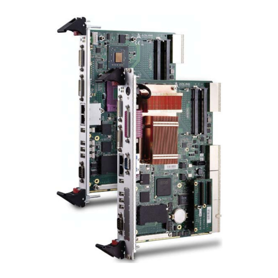
ADLINK Technology cPCI-6965 Series User Manual (116 pages)
Brand:
ADLINK Technology
| Category:
Motherboard
| Size: 3 MB
Table of Contents
Revision History
2
Preface
3
Table of Contents
7
List of Tables
11
List of Figures
13
1 Overview
15
Introduction
15
Features
16
Block Diagram
17
Figure 1-1: Cpci-6965 Series Block Diagram
17
Product List
18
Sbc
18
Rear Transition Module
18
Package Contents
19
CPU Module
19
Rear Transition Module
19
2 Specifications
21
Cpci-6965 SBC Specifications
21
Cpci-R6000-965(D) & Cpci-R6000(D)-L
24
Specifications
24
I/O Connectivity Table
25
Table 2-1: SBC I/O Connectivity
25
Table 2-2: RTM (4HP) I/O Connectivity
26
Table 2-3: RTM (8HP) I/O Connectivity
26
Power Requirements
27
Table 2-4: Compactpci Input Voltage Characteristics
27
Power Consumption
28
Table 2-5: Power Consumption of Intel® Core™2 Duo T7500 14 Table 2-6: Power Consumption of Intel® Celeron® 550
28
3 Functional Description
29
Intel® Core™2 Duo Processor T7500
30
Intel® Celeron® Processor 550
31
Chipset
32
Intel® GME965 Memory Controller Hub
32
Intel® ICH8 Mobile I/O Controller Hub
33
DVI
34
Super I/O
34
Battery
34
PMC Site
34
Onboard USB Flash
35
Figure 3-1: USB Flash Disk Mechanical Layout
35
4 Board Interfaces
37
Cpci-6965 SBC Board Layout
37
Figure 4-1: Cpci-6965 Board Layout
37
Cpci-6965 SBC Assembly Layout
38
Figure 4-2: Cpci-6965 SBC Assembly Layout
38
Cpci-6965 SBC Assembly Layout
39
Figure 4-3: Cpci-6965D SBC Assembly Layout
39
Cpci-6965, Cpci-6965D SBC Front Panel
40
Figure 4-4: Cpci-6965 Series Front Panel Layout
40
System Leds
41
Table 4-1: Cpci-6965 Front Panel System LED Descriptions
41
Cpci-R6000-965/R6000-L RTM Board Layout
42
Figure 4-5: Cpci-R6000-965, Cpci-R6000-L Board Layout
42
Cpci-R6000-965/R6000-L RTM Front Panel
43
Figure 4-6: Cpci-R6000-965, Cpci-R6000-L Front Panel
43
Cpci-R6000-965D/6000D-L RTM Board Layout
44
Figure 4-7: Cpci-R6000-965D, Cpci-R6000D-L Board Layout
44
Cpci-R6000-965D/R6000D-L RTM Front Panel
45
Figure 4-8: Cpci-R6000-965D, Cpci-R6000D-L Front Panel
45
Connector Pin Assignments
46
Table 4-2: USB Connector Pin Definition
46
Table 4-3: PS/2 Keyboard/Mouse Connector Pin Definition
46
Table 4-4: DVI-D Connector Pin Definition
47
Table 4-5: DVI-D Connector Pin Definition
48
Table 4-6: COM1-2 Serial Port Connector Pin Definition
48
Table 4-7: Parallel Port Connector Pin Definition
49
Table 4-8: Gbe Connector Pin Definitions
50
Table 4-9: Ethernet LED Status Definitions
50
Table 4-10: SATA Connector Pin Definition
51
Table 4-11: DB-6910SAT SATA Connector Pin Definition
51
Table 4-12: Compactflash Connector Pin Definition
52
Table 4-13: PMC Connector Pin Definition
54
Table 4-14: Compactpci J1 Connector Pin Definition
55
Table 4-15: Compactpci J2 Connector Pin Definition
56
Table 4-16: Compactpci J3 Connector Pin Definition
57
Table 4-17: Compactpci J5 Connector Pin Definition
58
Switch and Jumper Settings
59
Table 4-18: COM1 Mode Switch Settings
59
Table 4-19: COM2 Mode Switch Settings
60
Table 4-20: PMC V(I/O) Select Jumper Settings
61
5 Getting Started
63
CPU and Heatsink
63
Memory Module Installation
64
Installing the Memory Modules
64
Compactflash Card Installation
65
Hard Drive Installation
66
PCI Mezzanine Card (PMC) Installation
69
USB Flash Disk Module Installation
73
Installing the Cpci-6965 to the Chassis
74
RTM Installation
75
6 Driver Installation
77
Chipset Drivers
77
SCSI Driver
78
7 Utilities
79
Watchdog Timer
79
Using the Watchdog in an Application
79
Sample Code
80
Preboot Execution Environment (PXE)
83
8 BIOS Setup Utility
85
Starting the BIOS
85
Setup Menu
86
Navigation
86
Hotkey Descriptions
87
Main Setup
89
System Time/System Date
89
Advanced BIOS Setup
90
CPU Configuration
90
IDE Configuration
92
Floppy Configuration
93
Super IO Configuration
94
Hardware Health Configuration
96
Remote Access Configuration
97
USB Configuration
99
Advanced Pci/Pnp Settings
101
Boot Settings
102
Boot Settings Configuration
103
Boot Device Priority
104
Boot Device Groups
104
Security Setup
105
Password Support
105
Supervisor Password
106
User Password
106
Change Supervisor Password
106
Change User Password
106
Clear User Password
106
Change User Password
107
Chipset Setup
108
USB Functions
108
USB 2.0 Controller
108
HDA Controller
108
Onboard LAN BIOS Init
109
Exit Menu
110
Save Changes and Exit
110
Discard Changes and Exit
110
Discard Changes
111
Load Optimal Defaults
111
Load Failsafe Defaults
111
Important Safety Instructions
113
Getting Service
115
Advertisement
Advertisement
Related Products
ADLINK Technology cPCI-6930
ADLINK Technology cPCI-6910 Series
ADLINK Technology cPCI-6910/DCX20/M1G
ADLINK Technology cPCI-6910/DCX20/M2G
ADLINK Technology cPCI-6910/DCX16/M1G
ADLINK Technology cPCI-6910/DCX16/M2G
ADLINK Technology cPCI-6910/DXL16/M1G
ADLINK Technology cPCI-6910/DXL16/M2G
ADLINK Technology cPCI-6810B/P9
ADLINK Technology cPCI-6860A Series
ADLINK Technology Categories
Computer Hardware
Motherboard
PCI Card
Control Unit
Desktop
More ADLINK Technology Manuals
Login
Sign In
OR
Sign in with Facebook
Sign in with Google
Upload manual
Upload from disk
Upload from URL