
Related Manuals for ADLINK Technology IMB-M43H


Summary of Contents for ADLINK Technology IMB-M43H
- Page 1 IMB-M43H User’s Manual ® ATX Motherboard with 6th /7th Gen Intel Core™ i7/i5/i3 Processor ® and Intel H110 Chipset Manual Rev.: 0.3 preliminary Revision Date: October 9, 2017 Part Number: 50-1Z241-1000...
- Page 2 Preface Copyright Copyright 2017 ADLINK Technology, Inc. This document contains proprietary information protected by copyright. All rights are reserved. No part of this manual may be reproduced by any mechanical, electronic, or other means in any form without prior written permission of the manufacturer.
-
Page 3: Table Of Contents
IMB-M43H Table of Contents Preface ..........................ii Table of Contents ......................iii List of Figures ........................vi List of Tables ........................vii Introduction ........................ 1 1.1. Packing List ......................1 1.2. Optional Accessories ....................1 Specifications ......................3 2.1. Core System ......................3 2.2. -
Page 4: Preface
BIOS Setup ....................... 37 7.1. Title Menu ....................... 37 7.2. Main Menu ......................37 7.3. Advanced Menu ...................... 38 7.4. CPU Configuration ....................39 7.5. PCH-FW Configuration ................... 41 7.6. ACPI Settings ......................42 7.7. NCT6106D SuperIO Configuration ................42 7.8. - Page 5 IMB-M43H 7.38. USB HS Physical Connector ................... 55 7.39. HD Audio Configuration ..................56 7.40. Serial IO Configuration .................... 56 7.41. Serial IO I2C0 Settings .................... 56 7.42. Security Menu ......................56 7.43. Boot Menu ......................57 7.44. Save & Exit Menu ....................58 Safety Instructions ......................
-
Page 6: List Of Figures
List of Figures Figure 1: Functional Block Diagram ......................5 Figure 2: IO Panel Connector Locations ....................7 Figure 3: Connector Locations ......................... 8 Figure 4: Mechanical Dimensions ......................10 Figure 5: Mechanical Dimensions - IO Panel ..................11 Preface... - Page 7 IMB-M43H List of Tables Table 1: Connector Definitions ......................... 8 Table 2: Jumper and Switch Definitions ....................27 Table 3: System Memory Map .......................33 Table 4: IO Map ............................33 Table 5: IRQ Map ...........................35 Table 6: PCI Device Routing ........................35 Preface...
- Page 8 This page intentionally left blank. viii Preface...
-
Page 9: Introduction
IMB-M43H 1. Introduction IMB-M43H is an ATX motherboard supporting the Desktop 6th and 7th Generation Intel® Core™ i7/i5/i3 Processors with Intel® H110 Chipset, providing the most cost-competitive solution anywhere in embedded computing and fulfilling the specific needs of all users requiring 5 PCI add-on cards. With high-speed data transfer interfaces such as PCIe 3.0/2.0, USB 3.0, and SATA 6 Gb/s (SATA III), dual-channel DDR4 memory up to 32 GB... - Page 10 This page intentionally left blank. Introduction...
-
Page 11: Specifications
IMB-M43H 2. Specifications 2.1. Core System CPU: Desktop 6 Generation Intel® Core™ i7/i5/i3 Processor, LGA1151 socket • Intel® Core™ i7-6700, 3.4 GHz, 8M Cache, 14nm, 65W TDP, LGA1151 (4C/8T) • Intel® Core™ i7-6700TE, 2.4 GHz 8M Cache, 14nm, 35W TDP, LGA1151 (4C/8T) •... -
Page 12: Audio
2.4. Audio Audio Codec: Realtek® ALC892-CG Interfaces: 1x Mic-in, 1x Line-out and 1x Line-in connector (rear) 2.5. LAN1: Intel® I219-LM via RJ45 connector (rear) LAN2: Intel® I211-AT via RJ45 connector (rear) 2.6. Temperatures Operating Temperature: 0°C to 60°C ... -
Page 13: Functional Diagram
IMB-M43H 2.11. Functional Diagram Figure 1: Functional Block Diagram Specifications... - Page 14 This page intentionally left blank. Specifications...
-
Page 15: Mechanical Layout
IMB-M43H 3. Mechanical Layout 3.1. Connector Locations Figure 2: IO Panel Connector Locations External IO Connector Item Description Remarks KBMS PS2_USB78 USB2.0 PS2_USB78 VGA1 HDMI HDMI1 COM5 COM6 LAN+USB3.0 LAN1_USB12 LAN+USB3.0 LAN2_USB34 Line-In Port / Line-Out Port / MIC-In Port... -
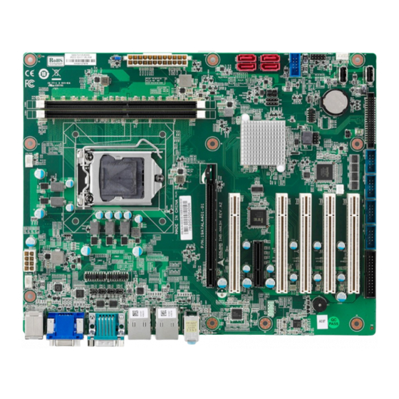
Page 16: Figure 3: Connector Locations
Figure 3: Connector Locations Table 1: Connector Definitions External IO Connector Item Description Remarks KBMS+USB PS2_USB78 VGA1 HDMI HDMI1 COM56 LAN1+USB3.0 LAN1_USB12 LAN2+USB3.0 LAN2_USB34 Audio AUDIO1 ATX POWER 8PIN ATX12V1 CHA_FAN CHA_FAN1 CPU_FAN CPU_FAN1 SYS_FAN SYS_FAN1 ATX POWER 24PIN EATXPWR1 AT/ATX mode header JPSON1 Mechanical Layout... - Page 17 IMB-M43H External IO Connector SATA1- SATA4 SATA1 USB56 USB56 Front Panel F_PANEL1 USB9 USB9 USB10 USB10 GPIO JDIO1 COM4 COM4 COM3 COM3 COM2 COM2 COM1 COM1 PRINT PORT LPT1 PCIEX16 PCIEX16_1 PCI1 PCI1 PCIEX4 PCIEX4_1 PCI2 PCI2 PCI3 PCI3 PCI4...
-
Page 18: Mechanical Dimensions
3.2. Mechanical Dimensions Top View Dimensions: mm Figure 4: Mechanical Dimensions Mechanical Layout... -
Page 19: Figure 5: Mechanical Dimensions - Io Panel
IMB-M43H Side View Dimensions: mm Figure 5: Mechanical Dimensions - IO Panel Mechanical Layout... - Page 20 This page intentionally left blank. Mechanical Layout...
-
Page 21: Connector Pinouts On Module
IMB-M43H 4. Connector Pinouts on Module See 3.1 Connector Locations on page 7 for connector locations. 4.1. Rear IO Connectors 4.1.1. HDMI Signal Name Signal Name HDMI1_CON_DP2 HDMI1_CON_DN2 HDMI1_CON_DP1 HDMI1_CON_DN1 HDMI1_CON_DP0 HDMI1_CON_DN0 HDMI1_CON_CKP HDMI1_CON_CKN HDMI1_DDC_CLK HDMI1_DDC_DATA +5V_HDMI HDMI1_CON_HPD 4.1.2. VGA Connector... - Page 22 4.1.3. USB Connectors USB 3.0, USB 2.0 Pin # Signal +5 VDC USB D- USB D+ Pin # Signal +5V_USB12 USB_CM_N1 USB_CM_P1 USB3_RX_CM_N1 USB3_RX_CM_P1 USB3_TX_CM_N1 USB3_TX_CM_P1 4.1.4. PS2 Combo connector Pin # Signal KB_DAT MS_DAT +5V_DUAL KB_CLK MS_CLK Connector Pinouts on Module...
- Page 23 IMB-M43H 4.1.5. COM connectors Signal Name Pin Signal Name COM_CN_DTR# COM_CN_TX COM_CN_RX COM_CN_DCD# COM_RI# COM_CTS# COM_RTS# COM_DSR# 4.1.6. Ethernet Connectors (LAN1, LAN2) Dual 10/100/1000Mbit/s LAN Ethernet controllers based on Intel® i219LM/i211AT, support PXE and WOL over both LANs. Pin #...
-
Page 24: Internal Connectors
4.2. Internal Connectors 4.2.1. USB56 Signal Name Signal Name Ground Ground KEY (no pin) No Connect/ OC The +5 VDC power on the USB headers is fused 4.2.2. SATA1, SATA2, SATA3, SATA4 Signal Name Description Ground Transmit diff data – positive Transmit diff data –... - Page 25 IMB-M43H 4.2.3. COM1, COM2, COM3, COM4 Serial Port is over-current protected Signal Name Description Signal Name Description DCD# Data Carrier Detect DSR# Data Set Ready Receive Data RTS# Request To Send TXD# Transmit Data CTS# Clear To Send DTR# Data Terminal Ready...
- Page 26 4.2.5. FP_AUDIO1 Signal Name Signal Name [Port 1] Left channel Ground [Port 1] Right channel PRESENCE# (Dongle present) [Port 2] Right channel [Port 1] SENSE_RETURN SENSE_SEND (Jack detection) Key (no pin) [Port 2] Left channel [Port 2] SENSE_RETURN 4.2.6. JCASE1 Signal Name Description SIO_CASEOPEN# Case open signal...
- Page 27 IMB-M43H 4.2.7. CPU_FAN1, CHA_FAN1, SYS_FAN1 Signal Name Description Ground +12 V FAN Power Tach FAN Tachometer FAN PWM The fan header supports +12 V at 1 A maximum 4.2.8. F_PANEL1 Signal In/ Out Description Signal In/ Out Description HDD Activity LED...
- Page 28 4.2.9. EATXPWR1 Signal Name Signal Name +3.3 V +3.3 V +3.3 V -12 V Ground Ground +5 V PS-ON# (power supply remote on/off) Ground Ground +5 V Ground Ground Ground PWRGD (Power Good) No connect +5 V (Standby) +5 V +12 V +5 V +12 V...
- Page 29 IMB-M43H 4.2.10. ATX12V1 Signal Name Signal Name Ground +12V Ground +12V Ground +12V Ground +12V 4.2.11. JLPC1 Signal Name Signal Name VCC3 LPC_AD3 PLTRST LPC_AD1 LPC_AD2 LPC_FRAME# LPC_AD0 CLK33M Connector Pinouts on Module...
- Page 30 4.2.12. SPI1 Signal Name Signal Name VCC3 SPI_CS# SPI_CLK SPI_MISO SPI_MOSI HOLD# 4.2.13. JPSON1 (Default 2-3) Signal Name Description PANSWIN# Power switch signal PSON_AT AT mode signal Connector Pinouts on Module...
- Page 31 IMB-M43H 4.2.14. JDIO1 (TTL High:3.3V / TTL Low:0V) Signal Name Signal Name DIO1 DIO17 DIO2 DIO18 DIO3 DIO19 DIO4 DIO20 DIO5 DIO21 DIO6 DIO22 DIO7 DIO23 DIO8 DIO24 DIO9 DIO25 DIO10 DIO26 DIO11 DIO27 DIO12 DIO28 DIO13 DIO29 DIO14 DIO30...
- Page 32 4.2.15. JSETCOM5, JSETCOM6 Signal Name Signal Name UART5_RXD COM5_RXD485 UART5_RXD COM5_RXD422 UART5_RXD COM5_RXD232 COM5_DCD# COM5_TX COM5_CN_DCD# COM5_CN_TX TXD485#1 RXD485P1 COM5_RX COM5_DTR# COM5_CN_RX COM5_CN_DTR# TXD485P1 RXD485#1 4.2.16. JCMOS1 (Default 1-2) Signal Name Description RTCRST# Reset CMOS Connector Pinouts on Module...
- Page 33 IMB-M43H 4.2.17. A8 (Default: NC) Signal Name Signal Name JDIO1. Pin40 JDIO1. Pin40 +12V JDIO1. Pin40 4.2.18. A9 (Default: NC) Signal Name Signal Name CN2 Pin1 CN2 Pin1 +3.3V CN2 Pin1 Connector Pinouts on Module...
- Page 34 4.2.19. A10 (Default: NC) Signal Name Signal Name +5V_DUAL CN4 Pin1 CN4 Pin1 +3.3V_DUAL CN4 Pin1 4.2.20. Signal Name Description NC/+3.3V/+5V select SMB_DATA SMBUS data SMB_CLK SMBUS clock Ground Connector Pinouts on Module...
-
Page 35: Jumper And Switch Settings
IMB-M43H 4.2.21. Signal Name Description NC/+3.3V/+5V select I2C_DATA I2C data I2C_CLK I2C clock Ground 4.3. Jumper and Switch Settings Table 2: Jumper and Switch Definitions Jumper Block Item Description Remarks JCMOS1 One 1x3 2.54mm pin header 1-2(default)=Normal, 2-3= Clear CMOS JPSON1 One 1x3 2.54mm pin header... - Page 36 Jumper Block JSETCOM5 One 2X9 2.0mm pin header JSETCOM6 RS232: 5-6,7-9,8-10,13-15,14-16(default) RS422: 3-4,,9-11,10-12,15-17,16-18 RS485: 1-2,9-11,10-12,15-17,16-18 COM5_S1~S4 master/slave and terminal selection COM6_S1~S4 master/slave and terminal selection One 2X3 2.0mm pin header NC(default)/+5V+12V Connector Pinouts on Module...
- Page 37 IMB-M43H Jumper Block One 2X3 2.0mm pin header NC(default)/+5V+12V One 2X3 2.0mm pin header NC(default)/+5V+12V Connector Pinouts on Module...
- Page 38 Connector Pinouts on Module...
-
Page 39: Driver Installation
5. Driver Installation Download the requisite drivers for your system from http://www.adlinktech.com and install. This chapter provides information on how to install the IMB-M43H device drivers under Windows XP. The device drivers are located in the following ADLINK All-in-One CD directories: Chipset... - Page 40 This page intentionally left blank. Driver Installation...
-
Page 41: System Resources
IMB-M43H 6. System Resources 6.1. System Memory Map Table 3: System Memory Map Address Range Address Range Size Description (4GB-2MB) FFE00000 – FFFFFFFF 2 MB High BIOS Area (4GB-18MB) – (4GB- FEE00000 – FEEFFFFF 1 MB MSI Interrupts 17MB-1) (4GB-20MB) – (4GB- FEC00000 –... - Page 42 Hex Range Device 002E-002F Motherboard resources 004E-004F Motherboard resources 0061-0061 Motherboard resources 0063-0063 Motherboard resources 0065-0065 Motherboard resources 0067-0067 Motherboard resources 0070-0070 Motherboard resources 0080-0080 Motherboard resources 0092-0092 Motherboard resources 00B2-00B3 Motherboard resources 0680-069F Motherboard resources FFFF-FFFF Motherboard resources 1800-18FE Motherboard resources 164E-164F Motherboard resources...
-
Page 43: Irq Map
IMB-M43H 6.3. IRQ MAP Table 5: IRQ Map IRQ# Device System timer COM2 COM1 COM3 COM4 System CMOS/real time clock COM5 COM6 Numeric data processor Intel Serial IO GPIO Host Controller Intel Chipset Smbus HD Audio Controller 6.4. PCI Device Routing Table... - Page 44 This page intentionally left blank. System Resources...
-
Page 45: Bios Setup
BIOS Information BIOS Vendor American Megatrends Core Version x.xx Compliancy UEFI x.x; PI x.x Project Version IMB-M43H x.xx.xx Build Date and Time mm/dd/yyyy hh:mm:ss AT/ATX Mode [x Mode] System Date mm/dd/yyyy Set the Data. Use Tab to switch between Data elements. -
Page 46: Advanced Menu
7.3. Advanced Menu Advanced Options Note CPU Configuration CPU Configuration Parameters. PCH-FW Configuration Configure Management Engine Technology Parameters. ACPI Settings System ACPI Parameters. NCT6106D Super IO Configuration System Super IO Chip Parameters. NCT6106D HW Monitor Monitor hardware status. S5 RTC Wake Settings Enable system to wake from S5 using RTC alarm. -
Page 47: Cpu Configuration
IMB-M43H 7.4. CPU Configuration CPU Configuration Options Note CPU Configuration Type (Show CPU type) Speed xxxx MHz L1 Data Cache L1 Instruction Cache L2 Cache L3 Cache L4 Cache SMX/TXT SW Guard Extensions (SGX) Software Controlled/Enabled/Disabled Enabled/Disabled Software Guard Extensions (SGX) - Page 48 CPU Configuration Options Note Intel (VMX) Virtualization Enabled/Disabled When enabled, a VMM can utilize Technology the additional hardware capabilities provided by Vanderpool Technology. Active Processor Cores All/1/2/3 Number of cores to enable in each processor package. Hyper-Threading Enabled/Disabled Enabled for Windows XP and Linux (OS optimized for Hyper- Threading Technology) and Disabled for other OS (OS not...
-
Page 49: Pch-Fw Configuration
IMB-M43H 7.5. PCH-FW Configuration Intel IGD SWSCI OpRegion Options Note ME Firmware Version ME Firmware Mode ME Firmware SKU ME File System Integrity Value ME Firmware Status 1 ME Firmware Status 2 NFC Support ME State Enable/Disable When Disabled ME will be put into ME Temporarily Disabled Mode. -
Page 50: Acpi Settings
7.6. ACPI Settings ACPI Settings Options Note S3 Video Repost Disabled/Enabled Enable or Disable S3 Video Repost PCIE# Wake from S5 Disabled/Enabled Enable or disable PCIE to wake the system from S5. Wake on Ring Disabled/Enabled Enable / Disable wake on ring function under ACPI S3/S4/S5. -
Page 51: Serial Port 1 Configuration
IMB-M43H 7.8. Serial Port 1 Configuration Serial Port 1 Options Note Serial Port Disabled/Enabled Enable or Disable Serial Port(COM) Device Settings IO=3F8h; IRQ=4 Change Settings Auto Select an optimal settings for Super IO Device 7.9. Serial Port 2 Configuration Serial Port 2... -
Page 52: Serial Port 5 Configuration
7.12. Serial Port 5 Configuration Serial Port 5 Options Note Serial Port Disabled/Enabled Enable or Disable Serial Port(COM) Device Settings IO=2E0h; IRQ=10 Change Settings Auto Select an optimal settings for Super IO Device RS485 Auto Flow Disabled/Enabled Disable or Enable RS485 Auto Flow Control Function (Make sure to set RS485 on the COM5 jumper header if this setting is... -
Page 53: Nct6106D Hw Monitor
IMB-M43H 7.15. NCT6106D HW Monitor H/W Monitor Options Note Smart Fan Smart Fan Function Page System temperature xx C CPU temperature (PECI) xx C SYS_Fan1 Speed xx RPM CPU_Fan1 Speed xx RPM CHA_Fan1 Speed xx RPM VCORE x.xxxV +12V x.xxxV x.xxxV... -
Page 54: Smart Fan Mode Configuration - Manual Mode
7.17. Smart Fan Mode Configuration – Manual Mode Smart Fan Mode Configuration Options Note SYS Smart Fan1 Mode Manual Mode/Thermal Cruise Mode SYS Smart Fan1 Mode SYS expect PWM Output/DC Voltage System FAN1 expect PWM Output/DC Voltage CPU Smart Fan Mode Manual Mode/Thermal Cruise Mode CPU Smart Fan Mode... -
Page 55: Console Redirection Settings
IMB-M43H 7.21. Console Redirection Settings COM1 Options Note Terminal Type VY100/VT100+/VT-UTF8/ANSI Type Select Bits per second 9600/19200/38400/57600/115200 Select serial port transmission speed. Data Bits Data Bits Parity None/Even/Odd/Mark/Space A parity bit can be sent with the data bits to detect some transmission error. -
Page 56: Csm Configuration
7.24. CSM Configuration CSM Configuration Options Note CSM Support Disabled/Enabled Enable/Disable CSM Support CSM16 Module Version Boot Option Filter UEFI and Legacy/ Legacy/UEFI ROMs priority Legacy only/ UEFI only Option ROM execution Network Do not launch/UEFI/Legacy Controls the execution of UEFI and Legacy PXE OpROM. -
Page 57: Chipset Menu
IMB-M43H 7.27. Chipset Menu Chipset Options Note System Agent(SA) Configuration System Agent(SA) Parameters PCH-IO Configuration PCH Parameters 7.28. System Agent (SA) Configuration South Bridge Options Note System Agent (SA) Configuration SA PCIe Code Version VT-d Capability Memory Configuration Memory Configuration... -
Page 58: Memory Configuration
7.29. Memory Configuration Memory Configuration Options Note Memory RC Version Memory Frequency Memory Timings DIMM_A1 DIMM_B1 Max TOULUD Dynamic/1GB/1.25GB/1.5GB/1.75GB/2GB/2.25GB/2.5GB/2.75GB/3GB/3.25GB/3.5GB Maximum 7.30. Graphics Configuration Graphic Configuration Options Note Graphics Configuration Primary Display Auto/IGFX/PEG/PCIE Select which of IGFX/PEG/PCIE Graphics device should be Primary Display Internal Graphics Auto/Disable/Enable... -
Page 59: Peg Port Configuration
IMB-M43H 7.31. PEG port Configuration PEG Port Configuration Options Note PEG Port Configuration PEG 0:1:0 Enable Root port Disabled/Enabled/Auto Enable or Disable the Root Port Max Link Speed Auto/Gen1/Gen2/Gen3 Configure PEG 0:1:0 Max Speed Detect Non-Compliance Device Disabled/Enabled Detect Non-Compliance PCI Express Device in PEG 7.32. -
Page 60: Pci Express Configuration
7.33. PCI Express Configuration PCI Express Configuration Options Note Link Training Retry Disabled/2/3/5 Defines number of Retry Attempts software will take to retrain the link if previous training attempt was unsuccessful. Link Training Timeout (uS) 1000 Defines number of Microseconds software will wait before polling ‘Link Training’... -
Page 61: Sata Configuration
IMB-M43H 7.35. SATA Configuration SATA Configuration Options Note SATA Controller(s) Enabled/Disabled Enable/Disable SATA Device. Determines how SATA controllers SATA Mode AHCI/Intel RST Premium operate. Indicates the maximum speed the SATA Controller Speed Default/Gen1/Gen2/Gen3 SATA controller can support. Serial ATA Port 1... -
Page 62: Usb Ss Physical Connector
7.37. USB SS Physical Connector USB SS Physical Connector Options Note Disable/Enable Enable/Disable this USB Physical Connector (physical port). Once USB SS Physical Connector #1 disabled, any USB device plug into the connector will not be detected by BIOS or OS. Disable/Enable Enable/Disable this USB Physical Connector (physical port). -
Page 63: Usb Hs Physical Connector
IMB-M43H 7.38. USB HS Physical Connector USB SS Physical Connector Options Note Disable/Enable Enable/Disable this USB Physical Connector (physical port). Once USB HS Physical Connector #1 disabled, any USB device plug into the connector will not be detected by BIOS or OS. -
Page 64: Hd Audio Configuration
7.39. HD Audio Configuration HD Audio Configuration Options Note Disable/Enable/Auto Control Detection of the HD-Audio HD Audio device. 7.40. Serial IO Configuration SerialIo Configuration Options Note Disabled/Enabled Enables/Disables SerialIO I2C0 Controller Controller Disabled/Enabled Enables/Disables the GPIO GPIO Controller Controller 7.41. Serial IO I2C0 Settings Serial IO I2C0 Settings Options... -
Page 65: Boot Menu
IMB-M43H 7.43. Boot Menu Boot Options Note Boot Configuration Number of seconds to wait for setup activation key. Setup Prompt Timeout 1(seconds) 65535(0xFFFF) means indefinite waiting. Select the keyboard NumLock Bootup NumLock State On/Off state. EVT2 change default. Enable or... -
Page 66: Save & Exit Menu
7.44. Save & Exit Menu Save & Exit Options Note Exit system setup after saving the Save Changes and Exit changes. Exit system setup without saving Discard Changes and Exit any changes. Reset the system after saving the Save Changes and Reset changes. -
Page 67: Safety Instructions
IMB-M43H Safety Instructions Read and follow all instructions marked on the product and in the documentation before you operate your system. Retain all safety and operating instructions for future use. • Please read these safety instructions carefully. • Please keep this User‘s Manual for later reference. - Page 68 This page intentionally left blank. BIOS Setup...
-
Page 69: Getting Service
5215 Hellyer Avenue, #110, San Jose, CA 95138, USA Tel: +1-408-360-0200 Toll Free: +1-800-966-5200 (USA only) Fax: +1-408-360-0222 Email: info@adlinktech.com ADLINK Technology (China) Co., Ltd. Address: 300 Fang Chun Rd., Zhangjiang Hi-Tech Park, Pudong New Area Shanghai, 201203 China Tel: +86-21-5132-8988 Fax: +86-21-5132-3588 Email: market@adlinktech.com... - Page 70 This page intentionally left blank. Getting Service...
Need help?
Do you have a question about the IMB-M43H and is the answer not in the manual?
Questions and answers