
Related Manuals for 3Com SuperStack II Switch 3000 10/100


Summary of Contents for 3Com SuperStack II Switch 3000 10/100
- Page 1 ® SuperStack II Switch 3000 10/100 User Guide ® Agent Software Version 3.1 http://www.3com.com/ Document No. DUA1694-2AAA03 Published June 1997...
- Page 2 3Com Technologies. the removable media in a directory file named LICENSE.TXT. If you are unable to locate a copy, please contact 3Com and a copy will be provided 3Com Technologies reserves the right to revise this documentation and to to you.
-
Page 3: Table Of Contents
ONTENTS Advanced Redundant Power System Socket 1-10 BOUT UIDE Reset Button 1-10 Introduction 1 Console Port 1-10 How to Use This Guide 1 Plug-in Module Slot 1-10 Conventions 2 Ethernet Address 1-10 Related Documentation 2 Unit Defaults 1-11 Managing the Switch 3000 10/100 1-12 Quick Start For SNMP Users 1-12 ETTING TARTED... - Page 4 Adding an Entry into the SDB 4-19 ETTING P FOR ANAGEMENT Deleting an Entry from the SDB 4-19 Methods of Managing the Switch 3-1 Specifying that an Entry is Permanent 4-19 Using the VT100 Management Interface 3-1 Setting Up Resilient Links 4-20 Using Telnet 3-2 Configuring Resilient Links 4-21 Managing Over The Network 3-2...
- Page 5 Setting up VLANs on the Switch 3000 10/100 5-8 How RMON Allows Proactive Management 5-24 Assigning a Port to a VLAN When Using Port VLAN How RMON Reduces the Traffic Load 5-24 Mode 5-9 RMON and the Switch 5-25 Specifying that a Port is a VLT port 5-9 RMON Features of the Switch 5-25 Setting Up VLANs Using AutoSelect VLAN Mode 5-10 About Alarm Actions 5-27...
- Page 6 ECHNICAL PECIFICATIONS ECHNICAL UPPORT Online Technical Services F-1 World Wide Web Site F-1 3Com Bulletin Board Service F-1 Access by Analog Modem F-1 Access by Digital Modem F-2 3ComFacts Automated Fax Service F-2 ® 3ComForum on CompuServe Online Service F-2...
-
Page 7: About This Guide
3000 10/100 is referred to as the Switch 3000 Information about the pin-outs relating to the Switch Appendix D 10/100 or Switch. 3000 10/100 Information about the Technical Specifications of the Appendix E Switch 3000 10/100 Information about the Technical Support available Appendix F from 3Com... -
Page 8: Conventions
Installation Guide. neously, the key names are linked with a plus Document Number DIA1694-2AAA0x sign (+). Example: Press [Ctrl]+[Alt]+[Del]. SuperStack II Switch 3000 10/100 Release Notes. Menu commands Menu commands or button names appear in Document Number DNA1694-2AAA0x and buttons italics. -
Page 9: Getting Started
PACE (Priority Access Control Enabled) for sup- performance switched connections to Ethernet and porting multimedia applications over Ethernet Fast Ethernet networks. 3Com’s SuperStack II architecture: Connects to Advanced Redundant Power Summary of Features System The Switch 3000 10/100 has the following features:... -
Page 10: Port Connections
MDIX-only. Most of the tion ends. 10BASE-T and 100BASE-TX ports in 3Com devices are MDIX-only. IFM should be enabled on a port if it is connected to another switch, or an endstation. IFM should be Plug-in Module disabled on a port connected to a repeater. -
Page 11: Full Duplex
About the Switch 3000 10/100 Full Duplex Virtual LANs (VLANs) The Switch 3000 10/100 provides full duplex sup- The Switch 3000 10/100 has a Virtual LAN (VLAN) port for all its ports, including Fast Ethernet Plug-in feature which allows you to build your network seg- Module ports. -
Page 12: Spanning Tree Protocol
1: G HAPTER ETTING TARTED Spanning Tree Protocol PACE The Switch 3000 10/100 supports the Spanning Tree The Switch 3000 10/100 supports PACE (Priority Protocol (STP) which is a bridge-based system for Access Control Enabled) technology, which allows providing fault tolerance on networks. STP allows multimedia traffic to be carried over standard Ether- you to implement parallel paths for network traffic, net and Fast Ethernet LANs. -
Page 13: Network Configuration Examples
Network Configuration Examples Network Configuration Examples Examples of how the Switch 3000 10/100 can be The following two illustrations show some exam- used in a VLAN-based network are given in Chapter ples of how the Switch 3000 10/100 can be used on your network. - Page 14 1: G HAPTER ETTING TARTED Figure 1-2 Increasing port density with the Switch 3000 10/100...
-
Page 15: Unit Overview - Front
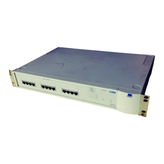
Unit Overview — Front Unit Overview — Front Figure 1-3 Switch 3000 10/100 front view... -
Page 16: 10Base-T / 100Base-Tx Ports
MDIX-only. Most of the Status Green Link is present; port is enabled. 10BASE-T and 100BASE-TX ports in 3Com devices Green flashing Link is present; port is disabled. are MDIX-only. Green flashing Refer to the “SuperStack II Switch... -
Page 17: Unit Overview - Rear
Unit Overview — Rear Unit Overview — Rear Figure 1-4 Switch 3000 10/100 rear view... -
Page 18: Power Socket
The fuse is suitable for both can be used to provide an additional high speed link 110V A.C. and 220–240V A.C. operation. For infor- to the rest of your network. 3Com provides a range mation on replacing fuses, refer to Appendix of Plug-in Modules;... -
Page 19: Unit Defaults
Unit Defaults 1-11 System Alarm Enabled Unit Defaults (bandwidth used) High threshold: 85% — No action The following table shows the factory defaults for Low threshold: 50% — No action the Switch 3000 10/100 features. Enabled System Alarm (percentage of High threshold: 85% —... -
Page 20: Managing The Switch 3000 10/100
Switch without any fur- Remote management is also possible using a Net- ther configuration. ® work Manager from 3Com’s Transcend product range. The management protocol is SNMP (Simple If you are using the IPX protocol, the Switch... -
Page 21: Entering An Ip Address For The Switch
Quick Start For SNMP Users 1-13 Entering an IP Address for the Switch 3Com Network Managers such as Transcend Work- Group Manager for Windows may automatically Connect a terminal to the console port of the configure the Switch 3000 10/100 to send traps to Switch 3000 10/100, refer to “Connecting a VT100... - Page 22 1-14 1: G HAPTER ETTING TARTED...
-
Page 23: Installation And Setup
NSTALLATION AND ETUP Water or moisture cannot enter the case of the Following Safety Information unit. Before installing or removing any components from Air-flow around the unit and through the vents in the Switch or carrying out any maintenance proce- the side of the case is not restricted. -
Page 24: Configuration Rules For Fast Ethernet
2: I HAPTER NSTALLATION AND ETUP Configuration Rules for Fast Ethernet Configuration Rules with Full Duplex The topology rules for 100Mbps Fast Ethernet are The Switch 3000 10/100 provides full duplex sup- slightly different to those for 10Mbps Ethernet. port for all its ports and Fast Ethernet Plug-in Figure 2-1 illustrates the key topology rules and pro- Module ports. - Page 25 Configuration Rules with Full Duplex Figure 2-1 Fast Ethernet configuration rules...
-
Page 26: Installing The Switch 3000 10/100
2: I HAPTER NSTALLATION AND ETUP Insert the three screws and fully tighten with a suit- Installing the Switch 3000 10/100 able screwdriver. Repeat steps 2 and 3 for the other side of the unit. Rack Mounting Insert the unit into the 19-inch rack and secure with The Switch is 1.5U high and fits in most standard suitable screws (not provided). -
Page 27: Wall Mounting
Installing the Switch 3000 10/100 Wall Mounting A single Switch can be wall-mounted. CAUTION: Disconnect any cables from the unit before continuing. Remove self-adhesive pads from the underside of the unit if they have been previ- ously fitted. Place the Switch the right way up on a hard flat sur- face, with the front facing towards you. -
Page 28: Powering-Up The Switch
2: I HAPTER NSTALLATION AND ETUP Powering-up the Switch Connecting an Advanced Redundant Power System (Advanced RPS) Connect the power cord to the IEC socket on the rear of the Switch, and to your mains socket. You can connect a SuperStack II Advanced RPS to an RPS socket on the Switch. -
Page 29: Connecting Equipment To The Console Port
Connecting Equipment to the Console Port Connecting a VT100 Terminal Connecting Equipment to the Console Port To connect a VT100 terminal directly to the console The Switch console port settings are set to: port on the Switch, you need a standard null modem cable: 8 data bits Connect one end of the cable to the console port... -
Page 30: Connecting A Workstation Running Slip
2: I HAPTER NSTALLATION AND ETUP Connecting a Workstation Running SLIP You can communicate with the Switch via the con- sole port from a workstation running SLIP (Serial Line Internet Protocol). In this way, you can perform out-of-band management using Telnet or SNMP. Cables required for this connection depend on the type of workstation you are using. -
Page 31: Setting
ETTING P FOR ANAGEMENT The Switch can support up to four management Methods of Managing the Switch user sessions concurrently (for example, one con- sole port and three Telnet connections). You can manage the Switch 3000 10/100 in four ways: You can establish VT100 management communica- Using the VT100 interface by connecting a VT100 tion with the Switch through two different inter-... -
Page 32: Using Telnet
Switch after 2–3 min- utes of inactivity. Each Network Manager provides its own user inter- face to the management facilities. 3Com's Before you can start a Telnet session you must set ® Transcend... -
Page 33: Obtaining A Registered Ip Address
Managing Over The Network If your network is internal to your organization only, you may use any arbitrary IP address. We sug- gest you use addresses in the series 191.100.X.Y, where X and Y are numbers between 1 and 254. Use 191.101.X.Y for the SLIP address. -
Page 34: Navigating The Vt100 Screens
3: S HAPTER ETTING P FOR ANAGEMENT Navigating the VT100 Screens Screen Conventions To differentiate types of information, the VT100 screens use the following conventions: Type of Shown on screen Description information as... ♦text♦ Choice Field Text enclosed with markers is a list from which you can select one option only. Press the spacebar to cycle through the options. -
Page 35: Keyboard Shortcuts
Navigating the VT100 Screens Keyboard Shortcuts Correcting Text Entry There are several special characters or combinations Use [Delete] on a VT100 terminal or [Backspace] on of characters that allow you to make shortcuts: a PC. This moves the cursor one space to the left and deletes a character. -
Page 36: Setting Up The Switch For Management
3: S HAPTER ETTING P FOR ANAGEMENT Setting Up the Switch for Management The following sections describe how to get started if you want to use an SNMP Network Manager to manage the Switch. It assumes you are already familiar with SNMP management. If not, we recom- mend the following publication: “The Simple Book”... -
Page 37: Logging On
Setting Up the Switch for Management Logging On At the Logon screen displayed in Figure 3-2, enter your user name and password (note that they are both case-sensitive): If you have been assigned a user name and pass- word, enter those details. If you are logging on for the first time (after installation or initialization), use a default user name and password to match your access... -
Page 38: After Logging On
3: S HAPTER ETTING P FOR ANAGEMENT After Logging On When you have successfully logged on to the Switch, the Main Menu screen is displayed as shown Figure 3-3. From here, you can select the options needed to manage the unit. Refer to the screen map on page 4-1. -
Page 39: Switch Management Setup
Setting Up the Switch for Management Switch Management Setup The Management Setup screen allows you to con- figure IP, IPX and SLIP parameters for the Switch. This screen also allows you to display screens for setting up the console port and traps. To access the Setup screen, from the Switch Main Menu screen, select the MANAGEMENT SETUP option. - Page 40 3-10 3: S HAPTER ETTING P FOR ANAGEMENT If you suspect that there is a problem with the SLIP Address If you are using SLIP, enter an address Switch that has not been detected by the Normal that has a network part different to the network tests, set this field to Extended and reset the Switch address of the Switch.
- Page 41 Setting Up the Switch for Management 3-11 SETUP TRAPS Select this button to display the setup screen for trap parameters. Trap setup is described in “Setting Up Traps” page 4-25. CONSOLE PORT Select this button to display the setup screen for console port parameters. Console port setup is described in “Setting Up the Console Port”...
-
Page 42: Logging Off
3-12 3: S HAPTER ETTING P FOR ANAGEMENT Logging Off If you have finished using the VT100 management interface, select the LOGOFF option from the bottom of the main menu. If you accessed the VT100 management interface using a Telnet session or modem connection, the connection is closed automatically. - Page 43 3000 10/100 ANAGING THE WITCH Chapters 4 and 5 describe all the management facil- If an ATM OC-3c Module is installed in the Switch, extra screens are available. Refer to the ities for the Switch. While following steps in these ®...
-
Page 44: Managing The Switch 3000
4: M 3000 10/100 HAPTER ANAGING THE WITCH Setting Up Users From the Main Menu, select USER ACCESS LEVELS. The User Access Levels screen is displayed as shown Figure 4-2. From this screen you can access the following: LOCAL SECURITY screen — This allows you to set up access levels for users on the Switch. -
Page 45: Creating A New User
Creating a New User Creating a New User These steps assume the User Access Levels screen is displayed. Select the CREATE USER option. The Create User screen is displayed, as shown in Figure 4-3. Fill in the fields and assign an access level for the new user. -
Page 46: Deleting A User
4: M 3000 10/100 HAPTER ANAGING THE WITCH Deleting a User These steps assume the User Access Levels screen is displayed. Select the DELETE USERS option. The Delete Users screen is displayed as shown in Figure 4-4. Use the spacebar to highlight the user that you want to delete. -
Page 47: Editing User Details
Editing User Details Editing User Details These steps assume the User Access Levels screen is displayed. Select the EDIT USER option. The Edit User screen is displayed, as shown in Figure 4-5. Fill in the fields as required. When you have completed the changes, select OK. The Edit User screen shows the following fields: User Name This read-only field shows the name of Figure 4-5... -
Page 48: Assigning Local Security
4: M 3000 10/100 HAPTER ANAGING THE WITCH Assigning Local Security The Local Security screen shows a matrix of options for access method (Console Port, Remote Telnet, Community-SNMP) and access level. These steps assume the User Access Levels screen is displayed: Select the LOCAL SECURITY option. -
Page 49: Choosing A Switch Management Level
Choosing a Switch Management Level Choosing a Switch Management Level The Switch Management screen allows you to: Choose between managing a port, the unit, or a VLAN Display screens for setting up the Switch Display a screen for managing the Switch Data- base Display screens for managing resilient links Display screens for managing STP... - Page 50 4: M 3000 10/100 HAPTER ANAGING THE WITCH STP Use this button to display screens for managing Spanning Tree Protocol (STP) information for the level of management you have chosen (port or VLAN). Refer to “Spanning Tree Protocol” page 5-11. STP is not supported over Asynchronous Transfer Mode (ATM).
-
Page 51: Setting Up The Switch Unit
Setting Up the Switch Unit Setting Up the Switch Unit With the Switch Management screen displayed, choose the management level unit, then select the SETUP button. The Unit Setup screen is displayed as shown in Figure 4-10. The screen shows the following: Unit Name This read-only field shows the type of device. - Page 52 VLAN by referring to a tiated, the speed and Duplex Mode of each link to ® VLAN Server database in 3Com’s Transcend the Switch is automatically detected, and the speed Enterprise Manager software. and Duplex Mode of each port is set accordingly.
- Page 53 Oversize Frames Forward / Discard This field allows you to specify whether the Switch forwards encap- sulated Token Ring frames from 3Com’s Token Ring products. Set this field to Forward if the Switch is connected to 3Com products which support Token Ring encapsulation (for example, the SuperStack II Switch 2000);...
-
Page 54: Setting Up The Switch Ports
4-12 4: M 3000 10/100 HAPTER ANAGING THE WITCH Setting Up the Switch Ports With the Switch Management screen displayed, choose the management level port, choose the appropriate port, then select the SETUP button. The Port Setup screen is displayed as shown in Figure 4-11. - Page 55 Setting Up the Switch Ports 4-13 IFM should be disabled if the port is connected to a If the port uses AutoSelect VLAN Mode (refer to repeated segment where the traffic is mainly local to the VLAN Configuration Mode field), you cannot that segment.
- Page 56 4-14 4: M 3000 10/100 HAPTER ANAGING THE WITCH CAUTION: The Duplex Mode of a link is not Plug-in Module ports are not auto-negotiating. If detected if the port on the other end of the link the port is a Plug-in Module port, the Speed/Duplex is not auto-negotiating.
- Page 57 VLAN by referring to a when it reaches the rising threshold: VLAN Server database in 3Com’s Transcend Enter- none — no action takes place prise Manager software.
- Page 58 4-16 4: M 3000 10/100 HAPTER ANAGING THE WITCH Falling Action none / event / enable / event + RENEGOTIATE If the port is auto-negotiating, this enable Use this field to specify the action for the button allows you to restart the auto-negotiation alarm to take when it reaches the falling threshold: process for the port.
-
Page 59: Setting Up The Switch Database (Sdb)
Setting Up the Switch Database (SDB) 4-17 There are three types of entries in the SDB: Setting Up the Switch Database (SDB) Ageing entries — Initially, all entries in the data- The Switch maintains a database of device addresses base are ageing entries. Entries in the database that it receives on its ports. -
Page 60: The Database View
4-18 4: M 3000 10/100 HAPTER ANAGING THE WITCH The Database View The Unit Database View screen, as shown in Figure 4-12, allows you to view and configure the Switch Database. To access the screen, ensure the Switch Manage- ment screen is displayed and you have chosen the management level unit. -
Page 61: Searching The Switch Database
Setting Up the Switch Database (SDB) 4-19 INSERT This button lets you insert an entry into the Adding an Entry into the SDB database. You cannot insert an entry for a port In the MAC Address field, type in the MAC address which uses AutoSelect VLAN Mode. -
Page 62: Setting Up Resilient Links
4-20 4: M 3000 10/100 HAPTER ANAGING THE WITCH When setting up resilient links, you should note the Setting Up Resilient Links following: You can configure a Switch to provide resilient links Up to six resilient link pairs can be configured on to another device so that network disruption is mini- a Switch 3000 10/100. -
Page 63: Configuring Resilient Links
Setting Up Resilient Links 4-21 Configuring Resilient Links With the Switch Management screen displayed, choose the port to be the main port in the resilient link pair, then select the RESILIENCE button. The Port Resilience screen is displayed as shown in Figure 4-14. -
Page 64: Creating A Resilient Link Pair
4-22 4: M 3000 10/100 HAPTER ANAGING THE WITCH Both Failed — Although the resilient link is Creating a Resilient Link Pair correctly configured, both links have failed. This Ensure that the port nominated as the standby port could be due to loose connections or cable dam- is not physically connected to the unit. -
Page 65: Viewing The Resilient Setup
Setting Up Resilient Links 4-23 Viewing the Resilient Setup With the Switch Management screen displayed, choose the management level Unit and select the RESILIENCE button. The Unit Resilience Summary screen is displayed as shown in Figure 4-15. This screen shows the cur- rent resilient link configuration for the unit, and allows you to access the Port Resilience screen for the resilient link pairs. - Page 66 4-24 4: M 3000 10/100 HAPTER ANAGING THE WITCH Pair Enable Enabled / Disabled This read-only field displays whether the resilient link pair is currently enabled or disabled. You enable or disable a resilient link pair using the Port Resilience screen described in “Configuring Resilient Links”...
-
Page 67: Setting Up Traps
Setting Up Traps 4-25 Setting Up Traps Traps are messages sent across the network to an SNMP Network Manager. They alert the network administrator to faults or changes at the Switch device. Your Network Manager may automatically set up traps in the Switch Trap Table. Check the documen- tation accompanying the network management software. -
Page 68: Setting Up The Console Port
4-26 4: M 3000 10/100 HAPTER ANAGING THE WITCH Setting Up the Console Port From the Switch Management Setup screen, described in Chapter 3, select the CONSOLE PORT button. The Console Port Setup screen is displayed as shown in Figure 4-17. - Page 69 Setting Up the Console Port 4-27 Speed 1200 / 2400 / 4800 / 9600 / 19200 This field allows you to select the correct line speed (baud rate) for your terminal or modem. If you have enabled auto-configuration, the line speed is set automatically.
-
Page 70: Resetting The Switch 3000 10/100
4-28 4: M 3000 10/100 HAPTER ANAGING THE WITCH Resetting the Switch 3000 10/100 If you suspect a problem with the Switch 3000 10/100, you can reset it. From the Main Menu, select the RESET option. The Reset screen is displayed as shown in Figure 4-18. -
Page 71: Initializing The Switch 3000 10/100
Initializing the Switch 3000 10/100 4-29 Initializing the Switch 3000 10/100 This screen allows you to perform a reset as described in the previous section, and in addition, returns non-volatile data stored on the unit to its factory defaults (shown on page 1-11). -
Page 72: Upgrading Software
3000 10/100 HAPTER ANAGING THE WITCH Upgrading Software When 3Com issues a new version of agent software for the Switch, you can obtain it from 3Com’s infor- mation delivery systems described in “Online Techni- cal Services” page F-1. For upgrading the ATM OC-3c Module software, refer to the “SuperStack II Switch ATM OC-3c... -
Page 73: Advanced Management
DVANCED ANAGEMENT With VLANs, you can define your network according Virtual LANs (VLANs) Setting up Virtual Local Area Networks (VLANs) on Departmental groups — For example, you can the Switch 3000 10/100 provide less time-consum- have one VLAN for the Marketing department, ing network administration and more efficient net- another for the Finance department, and work operation. -
Page 74: How Vlans Ease Change And Movement
VLAN 1. This is something that can be done auto- ® seen as a broadcast domain — physical LAN seg- matically if you have 3Com’s Transcend Enterprise ments that are not constrained by their physical Manager for Windows (v6.0 and above). -
Page 75: Vlans And The Switch 3000 10/100
Virtual LANs (VLANs) VLANs and the Switch 3000 10/100 Connecting VLANs to a Router The Switch 3000 10/100 supports VLANs which If the devices of a VLAN need to talk to devices in a consist of a set of switch ports. Each switch port different VLAN, each VLAN requires a connection to can only belong to one VLAN at a time, regardless a router. -
Page 76: Using Autoselect Vlan Mode
AutoSelect VLAN Mode. In this mode, the ports are automatically placed in the required VLAN by referring to a VLAN Server database in 3Com’s Transcend Enterprise Figure 5-3 Switch refers to the VLAN Server Manager v6.0 for Windows. -
Page 77: Using Non-Routable Protocols
5-10. For more information about the VLAN Server data- base, refer to the documentation supplied with 3Com’s Transcend Enterprise Manager. Using Non-routable Protocols If you are running non-routable protocols on your network (for example, DEC LAT or NET BIOS), devices within one VLAN are not be able to commu- nicate with devices in a different VLAN. -
Page 78: Vlan Configuration Example
Place ports 7–12 and 19–24 of all the Switch You can set up this configuration more easily if you 1000 units in VLAN 2. use 3Com’s Transcend Enterprise Manager applica- tions for all the management tasks. Connect a port on each Switch 1000 to a port in the Switch 3000 10/100. - Page 79 Virtual LANs (VLANs) Figure 5-5 VLAN configuration with a Switch 3000 10/100 as a basement switch...
-
Page 80: Setting Up Vlans On The Switch 3000 10/100
5: A HAPTER DVANCED ANAGEMENT Setting up VLANs on the Switch 3000 10/100 The VLAN Setup screen allows you to: Assign ports to VLANs, if those ports use Port VLAN Mode. View VLAN Setup information for the Switch. To access the VLAN Setup screen: From the Main Menu, select SWITCH MANAGE- MENT. -
Page 81: Assigning A Port To A Vlan When Using Port Vlan Mode
Virtual LANs (VLANs) Port ID 1 / 2 / 3 ... 13 This field displays the ID of Assigning a Port to a VLAN When Using Port the port currently selected in the listbox. VLAN Mode In the Port ID field, enter the ID of the required VLAN ID 1 / 2 / 3 ...16 If the port specified in the port. -
Page 82: Setting Up Vlans Using Autoselect Vlan Mode
5-10 5: A HAPTER DVANCED ANAGEMENT Setting Up VLANs Using AutoSelect VLAN Mode To set up VLANs using AutoSelect VLAN Mode, you need to: Specify information about the VLAN Server Specify that the Switch unit, or individual ports on the unit, use AutoSelect VLAN Mode Specifying Information About the VLAN Server The VLAN Server screen allows you to specify infor- mation about the VLAN Server. -
Page 83: Spanning Tree Protocol
Spanning Tree Protocol 5-11 As an example, Figure 5-8 page 5-12 shows a Spanning Tree Protocol network containing three LAN segments separated by three bridges. With this configuration, each seg- Using the Spanning Tree Protocol (STP) functionality ment can communicate with the others using two of your Switch makes your network more fault toler- paths. - Page 84 5-12 5: A HAPTER DVANCED ANAGEMENT Figure 5-8 A network configuration that creates loops Figure 5-10 Traffic flowing through Bridge B Figure 5-9 Traffic flowing through Bridges C and A...
-
Page 85: How Stp Works
Spanning Tree Protocol 5-13 How STP Works The Root Path Cost consists of the path cost of the Root Port of the bridge, plus the path costs across STP Initialization all the Root Ports back to the Root Bridge. Table 5-1 shows the default path costs for the Initially, the STP system requires the following before Switch 3000 10/100. -
Page 86: An Example
5-14 5: A HAPTER DVANCED ANAGEMENT An Example Figure 5-11 illustrates part of a network. All bridges have a path cost value assigned to each port, identi- fied by PC=xxx (where xxx is the value). Bridge A is selected by STP as the Root Bridge, because it has the lowest Bridge Identifier. -
Page 87: Stp Configurations
Spanning Tree Protocol 5-15 STP Configurations Figure 5-12 shows two possible STP configurations using SuperStack II Switch units: Configuration 1 — Redundancy for Back- bone Link In this configuration, a Desktop Switch and a Switch 3000 10/100 both have STP enabled and are connected by two Fast Ethernet links. -
Page 88: Enabling Stp On The Switch
5-16 5: A HAPTER DVANCED ANAGEMENT Enabling STP on the Switch To enable STP on your Switch: From the VT100 Main Menu, select SWITCH MAN- AGEMENT. The Switch Management screen is dis- played. In the Management Level field, choose Unit. Choose the SETUP button. -
Page 89: Configuring Stp On The Switch
Spanning Tree Protocol 5-17 Configuring STP on the Switch CAUTION: You should not configure any STP parameters unless you have considerable knowl- edge and experience with STP. Configuring the STP Parameters of VLANs The Switch has a completely separate STP system for each VLAN that you have specified. - Page 90 5-18 5: A HAPTER DVANCED ANAGEMENT Forward Delay 4 ... 30 This read-only field shows The time must be greater than, or equal to 2 X the time (in seconds) that the ports on the Switch (Hello Time + 1) and less than, or equal to spend in the listening and learning states.
-
Page 91: Configuring The Stp Parameters Of Ports
Spanning Tree Protocol 5-19 Configuring the STP Parameters of Ports The Port STP screen allows you to set up and manage the STP parameters of each port on the Switch. To access the Port STP screen: From the Main Menu, select SWITCH MANAGE- MENT. - Page 92 5-20 5: A HAPTER DVANCED ANAGEMENT Designated Cost This read-only field shows the Fast Start Enable / Disable This field allows you to path cost from the Root Bridge to the Designated specify whether the port goes directly to the For- Bridge Port for the current port’s segment.
-
Page 93: Rmon
RMON application supplied with when a pre-defined threshold is crossed. 3Com’s Transcend Enterprise Manager. The management workstation — Communi- cates with the RMON probe and collects the sta- tistics from it. The workstation does not have to... -
Page 94: About The Rmon Groups
5-22 5: A HAPTER DVANCED ANAGEMENT About the RMON Groups Alarms The IETF define nine groups of Ethernet RMON sta- The Alarms group provides a versatile, general tistics. This section describes these groups, and mechanism for setting thresholds and sampling details how they can be used. -
Page 95: Matrix
RMON 5-23 Matrix Events The Matrix group shows the amount of traffic and The Events group provides you with the ability to number of errors between pairs of devices on a LAN create entries in an event log and/or send SNMP segment or VLAN. -
Page 96: Benefits Of Rmon
5-24 5: A HAPTER DVANCED ANAGEMENT Benefits of RMON How RMON Reduces the Traffic Load Using the RMON features of your Switch has three Traditional network management involves a man- main advantages: agement workstation polling network devices at regular intervals to gather statistics and identify It improves your efficiency problems or trends. -
Page 97: Rmon And The Switch
Table 5-2 details the RMON support provided by stand-alone RMON probes have traditionally been the Switch. expensive. Therefore, 3Com’s approach has been to Table 5-2 RMON support supplied by the Switch build an inexpensive RMON probe into the Smart- Agent of each Switch. This allows RMON to be... - Page 98 5-26 5: A HAPTER DVANCED ANAGEMENT Table 5-2 RMON support supplied by the Switch When using the RMON features of the Switch, you should note the following: RMON Group Support supplied by the Switch After the default sessions are created, they have Hosts Although Hosts is supported by the Switch, there are no Hosts sessions defined on a new or...
-
Page 99: About Alarm Actions
RMON 5-27 About Alarm Actions Table 5-3 Alarm Actions You can define up to 700 alarms for the Switch. The Action High Threshold Low Threshold actions that you can define for each alarm are No action. shown in Table 5-3: Notify only. -
Page 100: About Default Alarm Settings
5-28 5: A HAPTER DVANCED ANAGEMENT About Default Alarm Settings About the Audit Log A new or initialized Switch has four alarms defined The Switch keeps an audit log of all management for each port: user sessions, providing a record of changes to any MIB including the RMON MIB. -
Page 101: Status Monitoring And Statistics
TATUS ONITORING AND TATISTICS This chapter describes how to view the current operating status of the Switch, how to display any error information in a fault log and how to carry out a remote poll to check the response of another net- work device. -
Page 102: Summary Statistics
6: S HAPTER TATUS ONITORING AND TATISTICS Summary Statistics With the Switch Management screen displayed, choose the management level unit, then select the STATISTICS button. The Summary Statistics screen is displayed as shown in Figure 6-1. The Summary Statistics screen lists values for the current counter against every port on the Switch and it is refreshed approximately every 2 seconds. -
Page 103: Port Statistics
Port Statistics Port Statistics With the Switch Management screen displayed, choose the management level port, then select the STATISTICS button. The Port Statistics screen is dis- played as shown in Figure 6-2. As well as showing statistics for the port, Port Statis- tics screen allows you access to traffic and error counter screens. - Page 104 6: S HAPTER TATUS ONITORING AND TATISTICS TRAFFIC STATISTICS Select this button to access traffic counters for the port. ERROR ANALYSIS Select this button to access error counters for the port.
-
Page 105: Port Traffic Statistics
Port Traffic Statistics Port Traffic Statistics With the Port Statistics screen displayed, select the TRAFFIC STATISTICS button. The Port Traffic Statistics screen is displayed as shown in Figure 6-3. The Port Traffic Statistics screen shows the follow- ing: Port ID The ID of the port you are currently manag- ing. - Page 106 6: S HAPTER TATUS ONITORING AND TATISTICS Fragments The total number of packets received The frame size ranges are: that were not an integral number of octets in length 64 octets or that had a bad Frame Check Sequence (FCS), and 65–127 octets were less than 64 octets in length (excluding fram- ing bits, but including FCS octets).
-
Page 107: Port Error Analysis
Port Error Analysis Port Error Analysis With the Port Statistics screen displayed, select the ERROR ANALYSIS button. The Port Error Analysis screen is displayed as shown in Figure 6-4. The Port Error Analysis screen shows the following: Port ID The ID of the port you are currently manag- ing. - Page 108 6: S HAPTER TATUS ONITORING AND TATISTICS CLEAR SCREEN COUNTERS Select this button to set all counters shown on the screen to zero. It is useful for trend analysis if you wish to see changes in counters over a short period of time. This button does not clear the counters on the device or affect counters at the network management workstation.
-
Page 109: Status Monitoring
Status Monitoring Status Monitoring The status screen provides read-only information about the Switch. This information may be useful for your technical support representative if you have a problem. To access the screen, from the Main Menu, select the STATUS option. The Status screen is displayed as shown in Figure 6-5. -
Page 110: Fault Log
The Fault Log displays read-only information about the Switch which is updated whenever an abnor- mal condition is detected. This information is for internal 3Com use only. You may be asked to quote this information if reporting a fault to your supplier. -
Page 111: Remote Polling
Remote Polling 6-11 Remote Polling The Remote Poll screen allows you to send a single frame to a remote device to see if that device is responding. This can help to locate the source of a network problem. It is also particularly helpful in locating devices that support IP, IPX and ping but are not manageable by SNMP. - Page 112 6-12 6: S HAPTER TATUS ONITORING AND TATISTICS...
-
Page 113: Safety Information
AFETY NFORMATION You must read the following safety information The appliance coupler, that is, the connector to before carrying out any installation or removal of the device itself and not the wall plug, must have components, or any maintenance procedures on a configuration for mating with an the Switch 3000 10/100. - Page 114 A: S PPENDIX AFETY NFORMATION It is essential that the mains socket outlet is Ensure that the power supply lead is discon- installed near to the unit and is accessible. You nected before opening the IEC connector fuse can only disconnect the unit by removing the cover or removing the cover of the unit.
-
Page 115: Power Supply And Fuse
Power Supply and Fuse Sockets for Redundant Power System (RPS) The unit automatically adjusts to the supply volt- Only connect a 3Com Redundant Power System to age. The fuse is suitable for both 110V A.C. and this socket. For details, follow the installation 220–240V A.C. -
Page 116: L'information De Sécurité Importante
A: S PPENDIX AFETY NFORMATION Pour U.S.A. et le Canada: L’information de Sécurité Importante Le cordon surmoulé doit être UL Certifié et CSA Certifié. AVERTISSEMENT: Les avertissements contiennent les directions que vous devez suivre pour votre sécu- Les spécifications minimales pour le cordon rité... -
Page 117: La Source De Courant Et Le Fusible
L’information de Sécurité Importante Assurer que l'entrée de la source d'alimentation La Source de Courant et Le Fusible soit débranchée avant d'ouvrir le couvercle de L'unité s'ajuste automatiquement à la tension d'ali- fusible du connecteur IEC ou d'enlever le couver- mentation. -
Page 118: Socle Pour Alimentation Multiple
AFETY NFORMATION Socle Pour Alimentation Multiple Brancher seulement une alimentation multiple de 3Com à cet socle. Suivre pour les détails les direc- tives de l'installation dans le manuel qui accompa- gne l'alimentation multiple. Les Ports RJ45 AVERTISSEMENT: Ceux-ci sont les prises de courant de données RJ45 protégées. -
Page 119: Wichtige Sicherheitsinformationen
Wichtige Sicherheitsinformationen Es ist wichtig, daß der Netzstecker sich in unmit- Wichtige Sicherheitsinformationen telbarer Nähe zum Gerät befindet und leicht erre- ichbar ist. Das Gerät kann nur durch WARNUNG: Warnungen enthalten Anweisungen, Herausziehen des Verbindungssteckers aus der die zur eigenen Sicherheit unbedingt zu beachten Steckdose vom Stromnetz getrennt werden. -
Page 120: Stromversorgung Und Sicherung
Originalsicherung ersetzen. Sicherung auswech- seln und die Klappe der Sicherungshalterung wieder schließen. Steckdose für Redundant Power System (RPS) Nur ein 3Com Redundant Power System an diese Steckdose anschließen. Für weitere Angaben die genauen Einbauanweisungen im Handbuch zum Redundant Power System befolgen. -
Page 121: Creen Ccess Ights
CREEN CCESS IGHTS The following table lists the rights assigned to each Screen Available to... level of user for accessing and editing Switch Port Traffic Statistics Monitor screens via the VT100 interface. Manager All access rights are read-and-write unless other- Security wise stated. - Page 122 B: S PPENDIX CREEN CCESS IGHTS Screen Available to... Screen Available to... VLAN STP Monitor read-only Trap Setup Monitor read-only Manager Manager Security Security VLAN Server Monitor read-only Console Port Setup Monitor read-only Manager Manager Security Security VLAN Setup Monitor read-only Software Upgrade Security Manager...
-
Page 123: C Trouble - Shooting
ROUBLE SHOOTING When managing the Switch, you may have a few The Plug-in Module Status LED lights yellow: problems; this appendix contains a list of known If the MGMT LED is flashing yellow, the Module problems and suggested solutions. If you have a has failed its Power On Self Test;... -
Page 124: Using The Vt100 Interface
C: T PPENDIX ROUBLE SHOOTING The SNMP Network Manager cannot access the Using the VT100 Interface device: Check that the device's IP address, subnet mask and The initial Main Banner screen does not dis- default router are correctly configured, and that the play: device has been reset. -
Page 125: Using The Switch
Using the Switch Check that the port through which you are trying to Using the Switch access the device is in VLAN 1 (the Default VLAN). Refer to “Setting up VLANs on the Switch 3000 You see network problems and the Packet LED 10/100”... - Page 126 C: T PPENDIX ROUBLE SHOOTING You have added the Switch 3000 10/100 to an Specify that the endstation entries are Non-ageing; already busy network, and response times and refer to “Setting Up the Switch Database (SDB)” traffic levels have increased: page 4-17.
- Page 127 Using the Switch You have set the speed and Duplex Mode of a port to Auto Negotiated, and you are seeing a large number of late events on the port (refer “Port Error Analysis” page 6-7): The port connected to the Switch 3000 10/100 port is not auto-negotiating and is operating in full duplex.
- Page 128 C: T PPENDIX ROUBLE SHOOTING...
-
Page 129: Null Modem Cable
OUTS Null Modem Cable PC-AT Serial Cable 9-pin to RS-232 25-pin 9-pin to 9-pin... -
Page 130: Modem Cable
D: P PPENDIX OUTS Modem Cable RJ45 Pin Assignments 9-pin to RS-232 25-pin... -
Page 131: Echnical Specifications
ECHNICAL PECIFICATIONS Physical Dimensions Height: 76mm (3.0in) x Width: 483mm (19.0in) x Depth: 300mm (12.0in) Weight: 4.4kg (9.7lbs) Environmental Requirements Operating Temperature 0–50°C (32–122°F) Storage Temperature -10–70 °C (14–158°F) Operating Humidity 10–95% relative humidity, non-condensing Standards EN60068 (IEC68) Safety Agency Certifications UL 1950, EN60950, CSA 22.2 No. - Page 132 E: T PPENDIX ECHNICAL PECIFICATIONS Standards Supported SNMP Protocols Used for Administration SNMP protocol (RFC 1157) UDP (RFC 768) MIB-II (RFC 1213) IP (RFC 791) Bridge MIB (RFC 1286) ICMP (RFC 792) Repeater MIB (RFC 1516) TCP (RFC 793) VLAN MIB (RFC 1573) ARP (RFC 826) RMON MIB (RFC 1271 and RFC 1757) TFTP (RFC 783)
-
Page 133: Echnical Support
3ComBBS contains patches, software, and drivers time of publication. For the very latest, we recom- for all 3Com products, as well as technical articles. mend that you access 3Com Corporation’s World This service is available via modem or ISDN 24 hours Wide Web site. -
Page 134: Access By Digital Modem
3ComFacts Automated Fax Service 3ComForum contains patches, software, drivers, and 3Com Corporation’s interactive fax service, technical articles about all 3Com products, as well 3ComFacts, provides data sheets, technical articles, as a messaging section for peer support. To use diagrams, and troubleshooting instructions on 3Com 3ComForum, you need a CompuServe account. -
Page 135: Support From Your Network Supplier
Belgium Netherlands 32 725 0202 If you are unable to contact your network supplier, 31 30 6029700 3Com Canada see the following section on how to contact 3Com. Calgary Montreal 403 265 3266 Ottawa 514 683 3266 Toronto 613 566 7055... -
Page 136: Returning Products For Repair
44 161 8737717 (Manchester) 44 1628 897000 (Marlow) Returning Products for Repair Before you send a product directly to 3Com for repair, you must first obtain a Return Materials Authorization (RMA) number. Products sent to 3Com without RMA numbers will be returned to the sender unopened, at the sender’s expense. -
Page 137: Glossary
LOSSARY 10BASE-T backbone The IEEE 802.3 specification for Ethernet over The part of a network used as the primary path for Unshielded Twisted Pair (UTP) cabling. transporting traffic between network segments. 100BASE-FX bandwidth 100Mbps Ethernet implementation over fiber. Information capacity, measured in bits per second, that a channel can transmit. - Page 138 LOSSARY broadcast Ethernet A message sent to all destination devices on the A LAN specification developed jointly by Xerox, network. Intel and Digital Equipment Corporation. Ethernet networks operate at 10Mbps using CSMA/CD to run broadcast storm over cabling. Multiple simultaneous broadcasts that typically Fast Ethernet absorb available network bandwidth and can cause network failure.
- Page 139 (usually not PACE larger than a floor or building). Characterized by high data rates and low error rates. Priority Access Control Enabled. 3Com’s innovative technology which works in conjunction with a latency switch to control the latency and jitter associated...
- Page 140 LOSSARY RJ45 SNMP Standard 8-wire connectors for 10BASE-T and Simple Network Management Protocol. A protocol 100BASE-TX networks. originally designed to be used in managing TCP/IP internets. SNMP is presently implemented on a RMON wide range of computers and networking equip- ment and may be used to manage many aspects of Remote Monitoring.
- Page 141 Switch’s local management capa- bilities. ® Transcend 3Com’s umbrella management system used to manage all of 3Com’s networking solutions. User Datagram Protocol. An Internet standard proto- col that allows an application program on one device to send a datagram to an application pro- gram on another device.
- Page 142 LOSSARY...
- Page 143 AutoSelect VLAN Mode 5-4 auto-configuration 4-26 10BASE-T / 100BASE-TX port 1-2, 1-8 specifying 5-10 connecting equipment to 2-7 3Com Bulletin Board Service (3ComBBS) F-1 connection type 4-26 3Com sales offices F-3 disabling access 4-6 3Com URL F-1 setting up 4-26...
- Page 144 NDEX Multicasts Received (summary) 6-2 Fwd Transitions 5-20 Multicasts Transmitted (summary) 6-2 Hello Time 5-17 Octets Received (port traffic) 6-5 Hold Time 5-18 Falling Action field 4-16 Octets Transmitted (port traffic) 6-5 Intelligent Flow Management 4-12 Falling Threshold% field 4-15 resetting to zero 6-2, 6-6, 6-8 IP or IPX Address 4-25 Fast Boot tests 3-9...
- Page 145 NDEX STANDBY Port 4-23 installing the Switch 2-4 Main Banner screen 3-6 Standby Port ID 4-21 Intelligent Flow Management 1-2 Main Menu screen 3-8 Status 3-10 enabling and disabling 4-12 MAIN Port field 4-23 Stop Bit 4-27 Intelligent Flow Management field 4-12 Main Port ID field 4-21 STP State 5-19 Interactive Access, disabling 4-13...
- Page 146 NDEX passwords Power Supply field 4-11 Root Path Cost 5-13 changing 4-5 Priority field 5-20 Root Port field 5-18 default 3-7 problem solving C-1 RPS. See Advanced RPS forgetting 4-5 new 4-3 Path Cost field 5-20 path costs quick start for SNMP users 1-12 safety information default 5-13 English A-1...
- Page 147 SLIP Address field 3-10 Root Path Cost 5-13 technical support F-1 SLIP SubNet Mask field 3-10 STP State field 5-19 3Com URL F-1 SNMP subnet mask of the unit 3-10 Bulletin Board Service F-1 enabling and disabling access 4-6 Summary Statistics screen 6-2...
- Page 148 NDEX User Access Levels screen 4-2 using unique MAC addresses 5-5 User Name field 4-3, 4-5 VLTs 5-8 users VLT Mode field 4-13 access levels 4-2 VLT Mode, selecting 4-13 changing names 4-5 VLTs 5-3, 5-8, 5-9 creating 4-3 VT100 interface default 3-7 accessing 3-1 deleting 4-4...
- Page 149 The repaired or replaced item will be shipped to Customer, at 3Com’s ARDWARE expense, not later than thirty (30) days after receipt of the defective product by 3Com. 3Com warrants its hardware products to be free from defects in workmanship and...
- Page 150 LECTRO AGNETIC OMPATIBILITY NFORMATION If this equipment does cause interference to radio or television reception, which can be FCC S TATEMENT determined by turning the equipment off and on, the user is encouraged to try to correct the interference by one or more of the following measures: This equipment has been tested with a class A computing device and has been found to comply with part 15 of FCC Rules.
Need help?
Do you have a question about the SuperStack II Switch 3000 10/100 and is the answer not in the manual?
Questions and answers