
Related Manuals for CDVI CDV-91


Summary of Contents for CDVI CDV-91
- Page 1 All manuals and user guides at all-guides.com 2 -Wire Intercom System USER MANUAL Model: CDV-91...
- Page 2 All manuals and user guides at all-guides.com...
-
Page 3: Parts And Functions
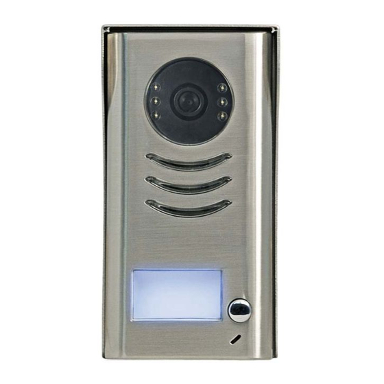
All manuals and user guides at all-guides.com 1.Parts and Functions Camera Lens Night View LED Speaker Nameplate Call Button Microphone Rainy Cover 90 mm 23 mm 2.Terminal Descriptions 1 2 3 Lock Control Jumper Doorstation Code DIP MIC adjustment SPK adjustment Main Connect Port S 2 + S - P L S 1 +... -
Page 4: Specifications
All manuals and user guides at all-guides.com • To select the lock type: see 5.2.1 , 5.2.2 Lock Control Jumper: • Total 4 door stations can be supported,see 6.1 Door Station Code DIP: • To connect the bus line and the electronic locks. Main Connect Port: •... -
Page 5: Mounting With Rainy Cover
All manuals and user guides at all-guides.com 4.2 Mounting With Rainy Cover 160-165cm 4.3 Placing Name Label Move the plastic cover away to open the transparent name label cover, insert a name paper, then put the plastic cover back to the panel. name label... -
Page 6: Adjusting Camera Angle
All manuals and user guides at all-guides.com 4.4 Adjusting Camera Angle Use a screwdriver to loosen the screw and then adjust the angle of the camera ,then fix the screw. 5.System Wiring and Connections 5.1 Basic Connection monitor L1 L2 PL S1+ S2+ S-... -
Page 7: Door Lock Controlled With Dry Contact
All manuals and user guides at all-guides.com 5.2 Electric Lock Connection 5.2.1 Door Lock Controlled with Internal Power Note: Electronic lock of Power-on-to-unlock type should be used. The door lock is limited to 12V, and holding current must be less than 250mA. The door lock control is not timed from Exit Button(EB). -
Page 8: Unlock Parameter Setting(Set On Monitor)
All manuals and user guides at all-guides.com connect one lock connect two locks Take off the Jumper Take off the Jumper POWER POWER SUPPLY SUPPLY LOCK LOCK LOCK 5.2.3 Unlock parameter setting(set on monitor) H/W : a1.3 S/W: V17.11.418.00 Manual Monitor Intercom Multimedia... -
Page 9: Multi Door Stations Connection
All manuals and user guides at all-guides.com 5.3 Multi Door Stations Connection 4# Camera 3# Camera 2# Camera 1# Camera ID=11 ID=01 ID=10 ID=00 monitors L1 L2 PL S1+ S2+ S- L1 L2 PL S1+ S2+ S- L1 L2 PL S1+ S2+ S- L1 L2 PL S1+ S2+ S- DIP=on,off,off A B C D... -
Page 10: With Dbc4 Wiring Mode
All manuals and user guides at all-guides.com 5.4.2 With DBC4 Wiring Mode monitor monitor 3 4 5 6 3 4 5 6 Impedance Code=15, DIP-6=on Code=14, DIP-6=on OFF ON switch DIP=on,off,off monitor monitor 3 4 5 6 3 4 5 6 Code=12, DIP-6=on Code=13, DIP-6=on monitor... -
Page 11: Dip Switches Settings Of Door Station
All manuals and user guides at all-guides.com 6.Setup ON(1) OFF(0) 6.1 DIP Switches Settings of Door Station Total 2 bits on the DIP switches can be configured.The switches can be modified either before or after installation. Bit state Descriptions Default setting, ID = 0(00), set to the first Door Station. ID = 1(10), set to the second Door Station. - Page 12 All manuals and user guides at all-guides.com Bit-1 to Bit-5 are used to User Code setting.The CDV-91 responds to 0~15 . Bit state User Code Bit state User Code Bit state User Code Code=0 Code=6 Code=11 3 4 5 3 4 5...
-
Page 13: Cables Requirements
All manuals and user guides at all-guides.com 7.Cables Requirements The maximum distance of the wiring is limited in the DT system. Using different cables may also affect the maxi- mum distance which the system can reach. The farest monitor monitor with two or four monitors monitor monitor... - Page 14 All manuals and user guides at all-guides.com...
- Page 15 All manuals and user guides at all-guides.com...
- Page 16 All manuals and user guides at all-guides.com The design and specifications can be changed without notice to the user. Right to interpret and copyright of this manual are preserved. Model: CDV-91...
Need help?
Do you have a question about the CDV-91 and is the answer not in the manual?
Questions and answers