Advertisement
Quick Links
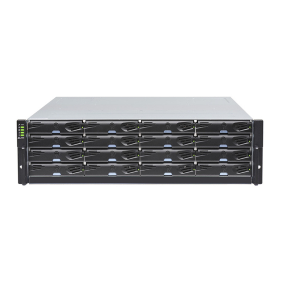
EonStor DS 1000 Series
Quick Installation Guide
Warning
• Only qualified service personnel should install and service this product to avoid injury.
• Observe all ESD procedures during installation to avoid damaging the equipment.
Preparing tools
1
Unpack the equipment and make sure the following tools are available before installation.
Refer to the Unpacking List for the exact amount of items included in the package.
NOTE
1-1. User-provided tools
1-2. Accessory box content
• Phillips screwdriver (mid-size)
• Screws: M5, M6, #10-32, #6-32
• Flat blade screwdriver (small-size)
• Cables: Power cord x 2
• Anti-static wrist wrap
2
Rackmount Installation
Due to the weight of the enclosure and installation procedure requirements, DO NOT
install HDDs before rackmounting and at least one other personnel should assist with
Warning
the installation.
There are two optional rackmounting kits available. Depending on the one you purchased, refer to the
following installation instructions.
1
2-1. Rack Ear Mount Kit
a. Contents
Item
Quantity
Description
Mounting bracket assembly, left-side
1
01
1
02
Mounting bracket assembly, right-side
03
Hexagon washer screws #6-32mm
8
04
Truss head screws M5 x 9.0mm
4
4
05
M5 cage nuts
6
06
M5 x 25mm
4
07
M6 x 25mm
4
08
#10-32 x 25.4mm
4
b. Installation
1. Determine the exact position for enclosure installation (front and rear rack posts).
2. Refer to the illustration below to insert cage nuts into the front rack post and truss head screws to secure
the slide rail.
Positions for chassis / M5 cage nut: Please refer to Rack Ear Mount Kit's section.
3. Adjust the length by loosening the four screws on the slide rail. Secure the slide rails to front and rear
posts using truss head screws and tighten the four screws on the slide to fix the length.
05
M5 x 9.0mm
Inner glide rail
4. Attach the inner glides to BOTH sides of the enclosure using flathead screws #6-32.
08
#6-32
© by Infortrend Technology, Inc. All rights reserved.
Z M0 0 0 1 1 0 G A Q0 2 8 1 3
b. Installation
1. Determine the exact position where the enclosure will be installed on the rack post (front and rear).
2. Insert the cage nuts into the front rack post.
Positions for chassis / M5 cage nut:
Front rack posts
Unit boundary
Unit boundary
3. Install the fixed rails to the rear posts and secure them using truss head screws.
2
3
4
5
04
M5 x 9.0mm
7
8
5. With the assistance of another person, lift and insert the enclosure onto the slide rail. Make sure the inner glides on both
sides of the enclosure meets the inner glide rail. Secure the enclosure using M5 or M6 screws from the front.
05
M5 x 9.0mm
3
Installing HDD
3-1. Small form factor HDD (2.5")
a. Removing the HDD tray
1. Press on the release button to open the bezel
and gently pull the hard drive tray out of the
enclosure.
b. Attaching the HDD
1. Place the hard drive into the drive tray. The
interface connector should face the open
side of the tray, while the label side should
face up. with the label of the hard drive
facing up.
2. Secure the HDD onto the tray according
to the following screw positions.
Rear rack posts
3U, M5 cage nut position
05
2U, M5 cage nut position
05
04
M5 x 9.0mm
a
Release button
Lock
Unlock
3U / 36-bay model
b
Tray
bezel
3U / 36-bay model
2.5 inch SAS HDD
2.5 inch SATA HDD
(with MUX board)
(without MUX board)
4. With one person holding the enclosure at the installation height, the other person can secure the enclosure
in place by placing four M5 x 25mm screws at the front and eight #6-32 screws on both sides (four on each
side).
If the rack did not require M5 cage nuts and has its own screw threads, then use the M6
or #10-32 screws for the front posts.
NOTE
3 #6-32
2-2. Slide Rail Kit
a. Contents
1
Item
Description
Quantity
Mounting bracket assembly, left-side
1
01
1
02
Mounting bracket assembly, right-side
4
03
Inner glides
2
Flathead screws #6-32 L4
6
04
05
Truss head screws M5 x 9.0mm
8
06
M5 cage nuts
4
7
M5 x 25mm
07
4
08
M6 x 25mm
4
09
#10-32 x 25.4mm
4
The 2.5 inch drive trays of the 3U / 36 bay model are not compatible with 2.5 inch drive trays
of other Small Form Factor (SFF) models. Make sure the installed drive tray model first
before replacing it. Replace drive trays only with corresponding model. Inserting the wrong
NOTE
drive tray model can lead to serious hardware damage.
3-2.Standard form factor HDD (3.5")
b. Attaching the HDD
a.Removing the HDD tray
1. The interface connector should face the open side of
Press the release button to open the bezel
the tray, while the label side should face up.
and gently pull the HDD tray out of the enclosure.
2. Secure the drive by fastening four (4) of the
supplied screws.
a
a
b
b
a. 3.5" SAS HDD
3.5" SATA HDD in single-controller systems
b. 3.5" SATA HDD in dual-controller systems
3-3. Inserting and securing the HDD tray
1. Insert with the tray bezel open.
2. Close the bezel, use a small-size flathead screwdriver,
turn the bezel lock to the lock position.
2.1 3U / 36-bay model only:
Once fully inserted, close the bezel till it's snapped.
6 M5 x 25mm
6 M5 x 25mm
3
2
5
6
9
8
a
a
c
b
b
a. 2.5" SAS HDD (without MUX)
b. 2.5" SATA HDD (with MUX)
c. MUX board screw locations
Advertisement

Related Manuals for Infortrend EonStor DS 1000 Series


Summary of Contents for Infortrend EonStor DS 1000 Series
- Page 1 2.5 inch SAS HDD 2.5 inch SATA HDD © by Infortrend Technology, Inc. All rights reserved. Z M0 0 0 1 1 0 G A Q0 2 8 1 3 (with MUX board) (without MUX board)
- Page 2 RS-232C port. License Application File. (The serial cable is provided as an accessory for dual-controller models. 6. Visit http://www.infortrend.com/DSLS to register software license. The license number For single-controller models, the serial is attached in the software license envelop. cable is user-supplied.) 7.
Need help?
Do you have a question about the EonStor DS 1000 Series and is the answer not in the manual?
Questions and answers