Table of Contents
Advertisement
Advertisement
Table of Contents

Subscribe to Our Youtube Channel
Related Manuals for Infortrend EonStor DS 3000 Series


Summary of Contents for Infortrend EonStor DS 3000 Series
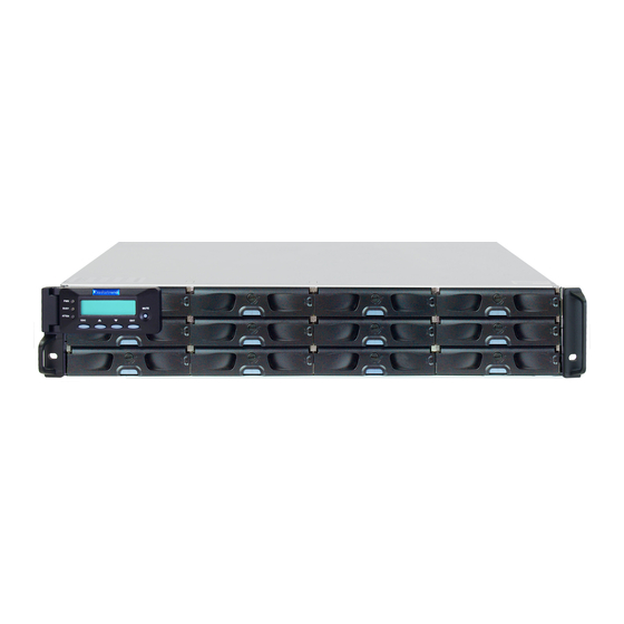
- Page 1 EonStor DS 3000 Series Hardware Manual...
- Page 2 (1) products, software, or options not certified and supported by Infortrend are used; (2) configurations not certified and supported by Infortrend are used; (3) parts intended for one system are installed in another system of different make or model.
-
Page 3: Table Of Contents
Table of Contents Safety precaution ..........................v About this manual ........................vi Revision history ..........................vii Hardware specifications ......................viii Package contents........................xii System package .........................xii Power cord, cable, and accessory boxes ................xii Pre-installed components ....................xiii Rackmount kit contents .....................xiii Chapter 1: Product Introduction Overview ..........................1-1 1.1.1 Model variations ....................1-1 1.1.2... - Page 4 2.3.6 Expansion connections ..................2-37 2.3.7 Management console connections ..............2-41 2.3.8 Power connection ....................2-42 Chapter 3: System monitoring Monitoring features ......................3-1 3.1.1 LEDs ........................3-2 3.1.2 Alarms and I C bus .....................3-8 Chapter 4: System maintenance Replaceable components ....................4-1 4.1.1 Power supply module/cooling module ..............4-1 4.1.2 Replacing the hard drive ..................4-4 4.1.3...
-
Page 5: Safety Precaution
Safety precaution Read these instructions carefully before you install, operate, or transport the Infortrend storage systems and expansion systems. Energy hazards precaution This equipment is intended to be used in a restricted access location, like a computer room. Only allow... -
Page 6: About This Manual
The use of Infortrend certified components is strongly recommended to ensure compatibility, quality, and normal operation with your Infortrend products. Please contact your distributor for a list of Infortrend certified components (e.g. SFP, SFP+, HBA card, iSCSI cable, FC cable, memory module, etc.). -
Page 7: Revision History
Revision history Version Date Description September 2015 Initial release January 2014 Added 3024B series (2.5” form factor) October 2014 Added 12 Gbps host port LED definition June 2017 Added 3000U series Wording fixes June 2018 Fixed cabling connection of 3000U series Removed all “unified”... -
Page 8: Hardware Specifications
Hardware specifications Specification summary Form factor - 2U 12-bay EonStor DS 3012U - 2U 24-bay EonStor DS 3024UB - 3U 16-bay EonStor DS 3016U - 4U 24-bay EonStor DS 3024U Controller Dual redundant controllers Cache memory - 8 GB DDR4 (2 x 4 GB) - 16 GB DDR4 (4 x 4 GB) - 32 GB DDR4 (4 x 8 GB) - 64 GB DDR4 (4 x 16 GB) - Page 9 Specification summary Drive advanced features S.M.A.R.T. support, automatic bad sector reassignment, dedicated bandwidth to each connected drive Supported drives 2.5-inch SAS SSD 2.5-inch SATA SSD* 2.5-inch 100000 RPM SAS HDD 3.5-inch 7200 RPM Nearline SAS HDD 3.5-inch 7200 RPM SATA HDD* * MUX board is required when using SATA drives NOTE: Refer to the Compatibility Matrix for the latest compatibility details.
- Page 10 Specification summary OS support - Windows Server 2008/R2* ® - Windows Server 2012/R2* ® - Windows Server 2016* ® - Red Hat Enterprise Linux ® ® - SUSE Linux Enterprise ® ® - Sun Solaris™ ® - MacOS ® - HP-UX - IBM ®...
- Page 11 Specification summary Dimension DS 3012U: 448 mm x 88 mm x 500 mm DS 3024UB: 448 mm x 88 mm x 500 mm DS 3016U: 448 mm x 130 mm x 500 mm DS 3024U: 448 mm x 175 mm x 500 mm Notes: •...
-
Page 12: Package Contents
Package contents Check the unpacking list for the complete list of contents and exact quantity of the components of your system. NOTE: The contents and quantity may vary depending on the system model and order requests. System package Rackmount kit Enclosure chassis Unpacking list and China RoHS Power cord, cable, and... -
Page 13: Pre-Installed Components
Pre-installed components Controller module* HDD tray PSU/Cooling module Rackmount kit contents Inner glides Rack ear mounting bracket for Slide rail mounting bracket rack ear mount kit for slide rail kit No 6-32 Hexagon M5 Cage nut M5 Truss washer screw head screw 25.4 mm 25 mm... -
Page 14: Chapter 1: Product Introduction
Chapter 1: Product Introduction Product introduction This chapter introduces the look and feel of EonStor DS 3000 systems, features, and the supported components. Overview This manual introduces EonStor DS 3000 systems that support 12 Gbps SAS hard drives. The systems are designed to utilize 2.5-inch and 3.5-inch hard drives. -
Page 15: Major Components
4U systems DS 3024U 1.1.2 Major components NOTE: Upon receiving the system, check the package contents and compare them to the Unpacking List. If one or more of the modules are missing, please contact your system vendor. Controller and interface The system has controllers, and each controller comes with pre-installed DIMM modules. -
Page 16: Chassis
The cooling type, which is built with the PSU, helps with the PSU’s temperature. Chassis This section describes the front and rear panels of EonStor DS 3000 series’ rugged storage chassis. These chassis are designed to allow installation to the rack or a cabinet. - Page 17 DS 3016U Number Part Description Buttons, This panel comprises of buttons, LEDs, and LCD panel for system LEDs, and events and firmware configuration. LCD panel Drive trays Each drive tray is hot-swappable and holds a 3.5-inch hard drive. Use the handles to push/pull the enclosure to/from the cabinet Handles installed in the slide rail rackmount system.
-
Page 18: Rear Panel
These hot-swappable PSUs provide power to the system and each modules PSU has a cooling module. WARNING! • DO NOT remove the redundant components. • DO NOT remove the redundant components without a replacement on hand. EonStor DS 3000 Series Hardware Manual... -
Page 19: Internal Backplane
1.2.3 Internal backplane The internal backplane is a circuit board that separates the front and rear parts of the chassis. This provides logic level signals and low voltage power paths. The thermal sensors and I C devices are embedded to detect system temperatures and PSU/cooling module operating status. This board is comprised of non user-serviceable components. - Page 20 NOTE: For more details regarding the LEDs and their respective status, refer to 3.1.1 LEDs. WARNING! If critical faults are indicated on the LED panel, verify the cause of the problem as soon as possible and contact your system vendor for a module replacement. EonStor DS 3000 Series Hardware Manual...
-
Page 21: Drive Tray Bezel
1.3.2 Drive tray bezel The drive tray bezel is designed to accommodate both SAS and SATA-interfaced hard disk drives. Get familiarized of the components of your system’s drive tray bezel. 2.5-inch drive tray 3.5-inch drive tray Number Part Description Rotary bezel lock This bezel lock secures the drive tray to the chassis . -
Page 22: Rear Panel Components
WARNING! You can only remove the controller when you already have the replacement. The EonStor controller is built of sensitive components. Unnecessary tampering may damage the controller. NOTE: For more information about super capacitor, see section 1.4.4 Super capacitor and flash backup module. EonStor DS 3000 Series Hardware Manual... -
Page 23: Expansion System Controller Module Interface
1.4.2 Expansion system controller module interface The expansion controller contains a circuit board within a metal canister, integrated with the hot- swap docking connectors at the backend. Two SAS wide ports on the interface faceplate connect to a managing DS system or other expansion systems. Expansion controller type 1 Expansion controller type 2 Number... -
Page 24: Psus And Cooling Modules
The PSUs have specific installation orientations for left and right cooling module slots. Refer to the label at the back of the expansion. • There are two upper temperature thresholds: one for event notification and the other for triggering high fan rotation speed. EonStor DS 3000 Series Hardware Manual 1-11... -
Page 25: Super Capacitor And Flash Backup Module
WARNING! • If any of the LEDs lights up in red, please contact your local vendor to request for a replacement immediately. • When removing the system cooling module, pull the module for about 3 inches then wait for at least 10 seconds before removing the whole module from the enclosure. -
Page 26: System Monitoring Features
The managing system communicates with the array via connection of the existing host links or the Ethernet link to the array’s Ethernet port. EonStor DS 3000 Series Hardware Manual 1-13... -
Page 27: Audible Alarms
1.5.2 Audible alarms The system comes with audible alarms that are triggered when certain active components fail or when specific controller or system thresholds exceed. Whenever you hear an audible alarm, you must determine the cause and solve the problem immediately. Event notification messages indicate the completion or status of array configuration tasks and are always accompanied by two or three successive and prolonged beeps. -
Page 28: Chapter 2: Hardware Installation
Chapter 2: Hardware installation Hardware installation This chapter describes installing the modular components such as hard drives, cards, and other optional installation or connections such as expansions and rackmount. Installation prerequisites Take note of the following installation prerequisites before you start with the installation: •... -
Page 29: Installation Procedures
Installation procedures This section details the installation procedures of the system, its components, and connections between equipment. The installation procedures in this section are in order, so it is strongly recommended that you follow the said order to reduce the time consumed during installation and prevent installation mistakes, technical mishaps, or physical injuries. - Page 30 Unit boundary 3U/4U, M 5 cage nut position 9.0 mm M5 2U, M 5 cage nut position Unit boundary Install the fixed rails to the rear posts using the truss head screws. 9.0 mm M5 EonStor DS 3000 Series Hardware Manual...
- Page 31 Installing the enclosure to the rack ear mount To install the enclosure to the rack ear mount, this requires an assistance of another person. While the other person holds the enclosure at the installation height, the other person secures the enclosure using four 25 mm M5 screws at the front and eight no.
- Page 32 Inner glide rail 9.0 mm M5 9.0 mm M5 Attach the inner glides to both sides of the enclosure using the flathead screws no. 6-32. No. 6-32 EonStor DS 3000 Series Hardware Manual...
- Page 33 With the assistance of another person, lift and insert the enclosure onto the slide rail. Ensure that the inner glides on both sides of the enclosure meet the inner glide rail. U N L O C K U N L O C K U N L O C K Secure the enclosure using the M5, M6, or no.
-
Page 34: Installing The Hard Drives
The system uses 12 Gbps SAS, SATA, and near-line 2.5-inch and 3.5-inch hard drives. IMPORTANT! • Ensure that you purchase the correct hard drives. • If you prefer using SATA hard drives in the attached expansions, ensure that you purchase MUX kits. EonStor DS 3000 Series Hardware Manual... - Page 35 Understanding the MUX kit’s port mechanism If you install a SATA hard drive in a dual-controller system, this may require an MUX board. The MUX board is paired with a hard drive in order to switch data signals between controllers A and B’s signal ports.
- Page 36 Get to know the exact order of the hard drives to avoid removing the drives out of the enclosure. DS 3012U DS 3024 UB DS 3016U DS 3024U IMPORTANT! Install at least four hard drives for RAID 5 and five hard drives for RAID 6 to create an initial volume. EonStor DS 3000 Series Hardware Manual...
- Page 37 Installing the hard drive into the drive tray and enclosure To install the hard drive into the drive tray and enclosure, follow the steps below: Press the release button to open the bezel, then gently pull out the tray. Orient the hard drive to the tray with the interface connectors facing the open side of the tray and the label is facing up.
- Page 38 Secure the drive to the correct holes of the tray using the four bundled screws. 2.5-inch drive tray 3.5-inch drive tray SAS HDD in single/dual controller systems SATA HDD in single controller systems SATA HDD in dual controller systems EonStor DS 3000 Series Hardware Manual 2-11...
- Page 39 Insert the assembled hard drive and tray to the enclosure with the tray bezel open. WARNING! Ensure that your system has all the drive bays occupied with the drive trays even if there are no hard drives installed. Without the drive trays, the ventilation is compromised and may cause overheating.
-
Page 40: Installing The Controller
Insert the controller carefully into the module slot. When you feel a contact resistance, push the controller with a small but careful force, then move the ejection levers upwards to secure the controller to the enclosure. EonStor DS 3000 Series Hardware Manual 2-13... -
Page 41: Installing The Host Boards
To secure the controller to the chassis, fasten two retention screws to the controller’s mounting holes under the ejection levers. Ejection lever Ejection lever Mounting hole Mounting hole 2.2.5 Installing the host boards NOTES: • A downtime may occur when upgrading the controller/host board. •... - Page 42 Insert the controller carefully into the module slot. When you feel a contact resistance, push the controller with a small but careful force, then move the ejection levers upwards to secure the controller to the enclosure. EonStor DS 3000 Series Hardware Manual 2-15...
-
Page 43: Connections
To secure the controller to the chassis, fasten two retention screws to the controller’s mounting holes under the ejection levers. Ejection lever Ejection lever Mounting hole Mounting hole Connections This section details the connection procedures of DS 3000 system to the expansions, power source, connection status, topologies, and other connection configurations. - Page 44 Usually, the optimum performance occurs from using Auto or 256 settings. For more information, refer to the firmware manual that came with your system. EonStor DS 3000 Series Hardware Manual 2-17...
-
Page 45: Fibre-Host Connections
2.3.2 Fibre-Host connections The Fibre Channel standard allows optical connections. The optical cables are used over long distances and have been proven to be more reliable. Due to the demands of high transfer rates, optical cables are preferred for a 4 Gbps, 8 Gbps, or 16 Gbps fiber connectivity and they are not vulnerable to EMI. The fibre host ports are connected to fibre channel host adapters (HBA), that feature SFP interface with full duplex transfer support in a PCIe interface. - Page 46 Remove the dust plug from the transceiver module. SPF transceiver module SPF transceiver module Dust plug Dust plug Insert the SFP module into one of the system host ports. The module snaps in place. EonStor DS 3000 Series Hardware Manual 2-19...
- Page 47 Remove the two protective caps from the LC-to-LC type cable. Save the protective caps for future use. Protective caps LC-to-LC cable Insert the LC-to-LC cable to the SFP transceiver module already connected to the system. You can hear a clicking sound, securing the cable in place. Remove the protective caps on the other end of the cable, then connect to an SFP transceiver module on a Fibre Channel switch port or a Fibre Channel host bus adapter (HBA) port.
- Page 48 Host servers Data path connection Fault-tolerant data paths NOTE: You need a multipathing software such as MPIO or Linux Device Mapper to control and optimize the access to logical drives via multiple data paths. EonStor DS 3000 Series Hardware Manual 2-21...
- Page 49 DAS (Direct-Attached) connection This connection has more disk drives over SAS expansion links. With this connection, you can create more logical groups of drives. These logical drives use more host channel IDs or LUN numbers. The two logical drives in the illustration below cannot equate the full power of the system. You can attach one or two more expansion enclosures to achieve more end-to-end performance.
- Page 50 I/Os across the preferred paths (active IDs on data paths). TPGS (Target Port Group Service) is supported so that the I/Os are routed to the preferred paths. EonStor DS 3000 Series Hardware Manual 2-23...
- Page 51 Switched fabric connection in single controller In this type of connection, each SFP port is connected to an FC switch then to the host adapters. Each logical partition is mapped to a single host channel ID. If you prefer path redundancy, you can map a logical partition to IDs residing on two different channels.
-
Page 52: Sas - Host Connections
WARNING! The SAS cables are sensitive and must be handled with care. To prevent interference within the rackmount, the cable routing path must be carefully planned and the cables must not be bent. EonStor DS 3000 Series Hardware Manual 2-25... - Page 53 DAS (Direct-Attached Storage) connection with redundant host path • Dual-controller models HB A 0 HB A 1 C H 0 A ID C H 1 B ID C H 0 A ID C H 0 A ID C H 1 A ID C H 0 B ID C H 0 A ID C H 0 A ID...
- Page 54 If your operating system is Windows 2003 server, you need a multipathing software such as MPIO ® or Linux Device Mapper to control and optimize the access to logical drives via multiple data paths. EonStor DS 3000 Series Hardware Manual 2-27...
- Page 55 DAS (Direct-Attached Storage) connection to two servers C H 0 AID C H 1 AID C H 0 AID C H 1 AID RAID NOTE: If you want your LUN to be accessible by multiple hosts, use locking or multipath access control.
-
Page 56: Ethernet - Host Connections
Multiple arrays or logical partitions can be created and made available separately via different IDs or LUNs on host ports. Usually, a RAID5 logical drive of 8 members sometimes brings optimal array performance. EonStor DS 3000 Series Hardware Manual 2-29... - Page 57 IMPORTANT! If you are using Microsoft’s software initiator, uncheck the embedded MPIO function when installing the software as the MPIO selection creates conflict with MPIO driver. High availability IP SAN with redundant controller H B A V LA N 1 V LA N 0 1 0 x 1 1 x...
- Page 58 IMPORTANT! In the event of single-controller failure, a logical drive drive is accessed via the host IDs managed by the alternate controller. The host and port IDs do not failover to the remaining controller. In this case, MPIO driver is necessary for path redundancy and controller failover. EonStor DS 3000 Series Hardware Manual 2-31...
- Page 59 Single-Controller with fault-tolerant path C H 0 ID 0 C H 0 ID 0 C H 2 ID 0 C H 2 ID 0 C H 1 ID 0 C H 1 ID 0 C H 3 ID 0 C H 3 ID 0 C H 0 ID 1 C H 0 ID 1 C H 2 ID 1...
- Page 60 LD must be assigned to controllers A and B to enable remote RAID configuration replication. • LD1 mapped to CH1 BID, CH0 AID, CH3 BID, and CH2 AID. LD must be assigned to controllers A and B to enable remote replication. EonStor DS 3000 Series Hardware Manual 2-33...
- Page 61 IMPORTANT! For systems operating in Windows 2003 server, and in the event of single-controller ® failure, a logical drive drive is accessed via the host IDs managed by the alternate controller. The host and port IDs do not failover to the remaining controller. In this case, MPIO driver is necessary for path redundancy and controller failover.
-
Page 62: Hybrid Host Connections
I/O, even if the iSCSI ports are not mapped to the host. As a result, the data transaction speed slows down to iSCSI connection’s level and the fast FC connection bandwidth may be spent without use. EonStor DS 3000 Series Hardware Manual 2-35... - Page 63 Utilizing Hybrid iSCSI ports for Data Replication NI C NI C NI C NI C HBA 0 HBA 1 HBA 0 HBA 1 HBA 0 HBA 1 HBA 0 HBA 1 SWITCH SWITCH RAID RAID CH0 FC CH1 FC SWITCH CH4 iSCSI CH5 iSCSI Ethernet...
-
Page 64: Expansion Connections
DS enclosure. • Ensure to set a unique ID on each enclosure so that the SAS WWN addresses of the disk drives are properly assigned. The SAN storage system firmware automatically manages these addresses. EonStor DS 3000 Series Hardware Manual 2-37... - Page 65 Configuration rules To connect the SAS interfaces across SAN storage and expansion systems, you must take note of the following: • Fault-tolerant links in a dual-controller combination Corresponding to the dual-port interfaces of the SAS drives, two physical links are available per disk drive, routed across the backplane board, then to a SAS expander, and interfaced via a 4x wide external SAS port.
- Page 66 With the help of the port selector mechanism on the MUX boards, the idea of SAS domain applies even when SATA drives are used in a dual-controller expansion system. Connecting expansion systems • Connecting dual-controller expansions or the last expansion EonStor DS 3000 Series Hardware Manual 2-39...
- Page 67 • SAN storage controller : SAS port IN Expansion , controller : SAS port OUT : SAS port IN : SAS port OUT • Expansion , controller Expansion , controller : SAS port IN : SAS port OUT • Expansion , controller Expansion or last, controller...
-
Page 68: Management Console Connections
For TCP/IP connection and firewall configuration, refer to your management software’s online help or user manual. If your network is not running the DHCP server protocols, you can use the default IP 10.10.1.1 if you are accessing for the first time. EonStor DS 3000 Series Hardware Manual 2-41... -
Page 69: Power Connection
2.3.8 Power connection Before connecting to a power source, ensure that all components are properly installed and the management interfaces are properly connected. Take a look at the list below and check the following: The hard drives are correctly installed to the drive trays. All drive trays are installed to the system, whether or not they contain a hard drive. - Page 70 The system is now ready. You can start configuring the ES80xx system. ES80xx x The system is ready for I/O operation. Ready NOTE: When turning ON the DS system, wait for the LCD screen to display READY or No Host LUN. EonStor DS 3000 Series Hardware Manual 2-43...
- Page 71 • Controller module LEDs Number Name Status Cache Dirty Host Busy Control Status CBM Status NOTE: Refer to chapter System maintenance for more information regarding the LED description. • PSU and cooling module LED 2-44 Chapter 2: Hardware installation...
- Page 72 Flush all cached data using the controller’s shutdown function to prepare the RAID system for a safe power shutdown. To do this, refer to the LCD screen with the illustrated order below: EonStor DS 3000 Series Hardware Manual 2-45...
-
Page 73: Chapter 3: System Monitoring
This chapter details the monitoring features and the status of EonStor DS 3000 systems. Monitoring features The EonStor DS 3000 series is equipped with self-monitoring features the help you keep track of the system’s operating status. You can monitor your system’s status with the following features: Firmware •... -
Page 74: Leds
3.1.1 LEDs This section details the system LEDs and their descriptions. Front panel LEDs • Panel LEDs Number LED name Color Description Power The system is ON and the system status is normal. (PWR) The system is OFF or the system has failed. Busy There is an active traffic on the host/drive channels. - Page 75 CBM Status supercapacitor or flash module. • Either the supercapacitor or the flash module is missing. The supercapacitor is charging. Restore Successfully reset the controller after the press and hold Default the Restore Default button. EonStor DS 3000 Series Hardware Manual...
- Page 76 • 1 G Ethernet management port LEDs Number LED name Status Description 1 Gb connection is established. • 10/100 Mb connection is established. Speed • No connection is established. A connection is established. Link/Active Flashing Data I/O is ongoing. No connection is established. •...
- Page 77 4 Gb connection is established. No connection is established. NOTE: For higher and speedier transfer rates, we suggest you to use optical cables for 4/8 Gb fiber connectivity. These cables are not susceptible to EMI (electromagnetic interference). EonStor DS 3000 Series Hardware Manual...
- Page 78 • Converged host board LEDs Number LED name Color/ Description Status A connection is established. Link A link is broken. Color/ 16 G Fibre 8 G Fibre 10 G Ethernet Status channel channel 16 G FC 8 G FC 10 G Ethernet Speed 8 G FC 4 G FC...
- Page 79 One of the PHYs has failed. All PHYs are offline. 12 Gb link speed Speed 6 Gb/3 Gb link speed No connection The controller is operating normally. • A component failure occurred. • Initialization is ongoing. EonStor DS 3000 Series Hardware Manual...
-
Page 80: Alarms And I C Bus
• PSU/Cooling module LED Color Description The system is connected to the power source but the system is not turned on. The PSU/cooling module is operating normally. The PSU/cooling module is faulty. The PSU LED alerts you of the current status of your PSU and cooling module components. When either of the components fails, you must replace the PSU immediately. -
Page 81: Chapter 4: System Maintenance
Chapter 4: System maintenance System maintenance This chapter provides maintenance and replacement procedures of replaceable components of your EonStor DS 3000 system. Replaceable components Your EonStor DS system is comprised of replaceable components: • PSU module • Hard disk drives WARNING! •... - Page 82 Replacing the PSU/cooling module Replace the defective PSU/cooling module immediately, but only if you have the replacement. WARNING! Although the system can still operate with a defective PSU, it is not recommended to use it for an extended period of time. NOTE: For more information, contact your system vendor.
- Page 83 When you feel a resistance, push the extraction handle to lodge the PSU/cooling module to the back-end connectors. Fasten the thumb screw to secure the PSU to the system. Connect the power cord. Turn on the PSU module. EonStor DS 3000 Series Hardware Manual...
-
Page 84: Replacing The Hard Drive
4.1.2 Replacing the hard drive WARNING! • Ensure to have a replacement ready before replacing the hard drive. DO NOT leave the drive tray open for long periods to prevent disruption of internal airflow. • Handle the hard drives with extreme care. Hold them by the edges and avoid touching the circuits and interface connectors. - Page 85 Remove the retention screws from the drive tray to dislodge the hard drive. 2.5-inch drive tray 3.5-inch drive tray SAS HDD in single/dual controller systems SATA HDD in single controller systems SATA HDD in dual controller systems EonStor DS 3000 Series Hardware Manual...
- Page 86 Install the replacement hard drive to the drive tray and secure the drive using the retention screws you removed in step 3. Insert the assembled hard drive and drive tray to the bay with the front bezel open. When the tray is fully inserted to the bay, close the front bezel. IMPORTANT! Ensure that there is no more drive error reported.
-
Page 87: Replacing The Controller Module
Disconnect all cables from the controller module that you want to be replaced. Loosen the screws that secure the controller module’s ejection levers to the chassis. Ejection lever Ejection lever Mounting hole Mounting hole EonStor DS 3000 Series Hardware Manual... - Page 88 Push down the ejection levers to dislodge the controller from the system (A), then pull to remove from the enclosure (B). Insert the replacement controller carefully into the controller module slot. When you feel a contact resistance, push the controller with a small but careful force (A), then move the ejection levers upwards to secure the controller to the enclosure (B).
-
Page 89: Replacing The Memory Module
Shut down your system, unplug the power cords, then remove the controller. Wait for a minute for the remaining electric current to dissipate. NOTE: See section 4.1.3 Replacing the controller module for details. Look for the DIMM slots in the controller. EonStor DS 3000 Series Hardware Manual... - Page 90 Push down the clips to release the DRAM module from the DIMM socket. Insert the replacement DIMM carefully into the DIMM socket, with the DIMM’s notch aligned to the DIMM socket’s notch guide. Reinstall the controller module into the chassis. 4-10 Chapter 4: System maintenance...
-
Page 91: Replacing The Cbm (Cache Backup Module) Components
Shut down your system, unplug the power cords, then remove the controller. Wait for a minute for the remaining electric current to dissipate. NOTE: See section 4.1.3 Replacing the controller module for details. From the controller board, disconnect the 4-pin connector from the charge board. EonStor DS 3000 Series Hardware Manual 4-11... - Page 92 Loosen the screw that secures the super capacitor to the controller. Remove the screw, lift the super capacitor in a 45° angle (A), then remove the super capacitor from the chassis (B). 4-12 Chapter 4: System maintenance...
- Page 93 (A), then secure it with the screw (B) you removed in step 3. From the controller board, connect the 4-pin connector to the charge board. Insert the controller back to the enclosure. EonStor DS 3000 Series Hardware Manual 4-13...
- Page 94 Replacing the FBM (Flash Backup Module) You can install two FBMs in the controller. If there are two host boards installed, you must remove the second host board if you want to gain access to both FBMs. NOTE: Refer to section 4.1.6 Replacing the host board when replacing/uninstalling a host board. To replace the FBM: Shut down your system, unplug the power cords, then remove the controller.
- Page 95 (B), then secure the FBM to the board with a screw (C) you removed in step 2. Insert the controller back to the enclosure. EonStor DS 3000 Series Hardware Manual 4-15...
-
Page 96: Replacing The Host Board
4.1.6 Replacing the host board Before installing the host board, you must take note of the following considerations: • If you’re replacing the host board for an upgrade, a controller/host board downtime may occur. • If you add or replace a host board, the firmware automatically restores the system to its factory settings. -
Page 97: Appendices
Appendices Appendices Certifications Summary Safety UL 60950-1 second edition BSMI CNS 14336-1: 99 年版 CB IEC 60950-1:2005 (Second Edition) + Am 1:2009 + Am 2:2013 EAC TP TC 004/2011, TP TC 020/2011 CE EN 55032:2012 +AC:2013/EN61000-3-2:2014 /EN 61000-3-3: 2013/EN 55024:2010+A1:2015 BSMI (CNS 13438) FCC (FCC Part 15, subpart B) Environment... -
Page 98: Contact Information
Contact information Infortrend Technology, Inc. (HQ Taiwan) Address: 8F, No. 102, Section 3, Jhongshan Road, Jhonghe District, New Taipei City 23544, Taiwan Telephone: +886-2-2226-0126 Fax: +886-2-2226-0020 Email: sales.tw@infortrend.com Website: https://www.infortrend.com/tw/Home Support: http://support.infortrend.com/Account/Logon Infortrend Japan, Inc. Address: 6F Okayasu Bldg., 1-7-14 Shibaura, Minato-Ku, Tokyo, 105-0023 Japan... - Page 99 Support: http://support.infortrend.com/Account/Logon Czech Republic sales office Email: sales.cz@infortrend.com, cs.eu@infortrend.com Website: https://www.infortrend.com/cz/Home Support: http://support.infortrend.com/Account/Logon France sales office Email: sales.fr@infortrend.com, cs.eu@infortrend.com Website: https://www.infortrend.com/fr/Home Support: http://support.infortrend.com/Account/Logon Italy sales office Email: sales.it@infortrend.com, cs.eu@infortrend.com Website: https://www.infortrend.com/it/Home Support: http://support.infortrend.com/Account/Logon EonStor DS 3000 Series Hardware Manual...
- Page 100 Germany/Deutschland GmbH sales office Email: sales.de@infortrend.com, cs.eu@infortrend.com Website: https://www.infortrend.com/de/Home Support: http://support.infortrend.com/Account/Logon Poland sales office Email: sales.pl@infortrend.com, cs.eu@infortrend.com Website: https://www.infortrend.com/pl/Home Support: http://support.infortrend.com/Account/Logon Middle East sales offices Email: sales.meat@infortrend.com Website: https://www.infortrend.com/ae/Home Support: http://support.infortrend.com/Account/Logon India sales office Email: sales.in@infortrend.com Website: https://www.infortrend.com/in/Home Support: http://support.infortrend.com/Account/Logon...
Need help?
Do you have a question about the EonStor DS 3000 Series and is the answer not in the manual?
Questions and answers