
Related Manuals for Datalogic PowerScan BT8300


Summary of Contents for Datalogic PowerScan BT8300
-
Page 1: Powerscan Bt8300 Family
® PowerScan BT8300 Family Industrial Handheld Bar Code Reader with Bluetooth® Wireless Technology Product Reference Guide... - Page 2 An Unpublished Work - All rights reserved. No part of the contents of this documentation or the procedures described therein may be reproduced or transmitted in any form or by any means without prior written permission of Datalogic Scanning, Inc. or its subsidiaries or affiliates ("Datalogic" or “Datalogic Scanning”). Owners of Datalogic products are hereby granted a non-exclusive, revocable license to reproduce and transmit this documentation for the purchaser's own internal business purposes.
-
Page 3: Table Of Contents
Setup Procedures ............................11 4.2.1 Restore PowerScan BT 8300 Default ....................11 Connecting the PowerScan BT8300 ....................... 12 4.3.1 Overview ............................12 PowerScan™ BT8300/BC 8030-BT Configuration ................... 12 PowerScan™ BT8300/Bluetooth-Enabled PC Configuration ..............12 ... - Page 4 Default Parameters for POS Terminals ....................149 5.16 Firmware Upgrade ........................... 150 5.17 16-Key PowerScan BT8300-DK Display and Keypad Parameters ............150 5.17.1 16-key Keyboard Data Format Enable/Disable ................ 150 5.17.2 Scanner Code ID ........................151 ...
-
Page 5: General View
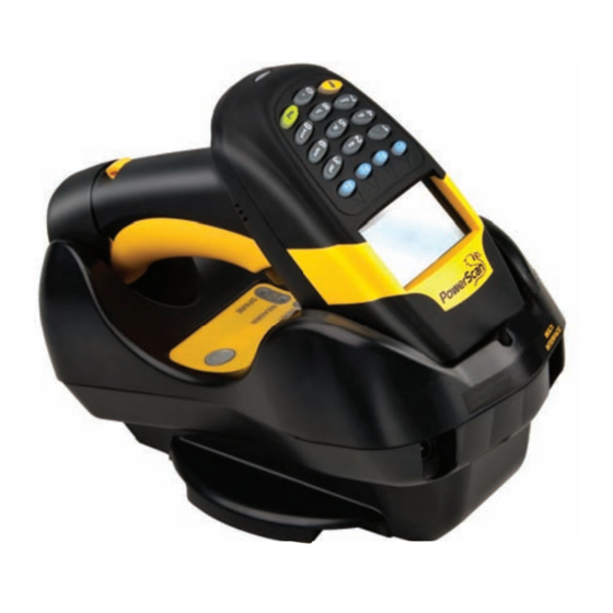
GENERAL VIEW GENERAL VIEW POWERSCAN™ BT8300 READERS LEDs POWERSCAN™ BT8300 Laser Output Battery Cover Window Trigger Figure A – PowerScan™ BT8300 Series Readers Laser Output Window Display Keypad LEDs Figure B – PowerScan™ BT8300 Series Readers with Display Product Reference Guide... - Page 6 PowerScan BT8300 readers If it already has a connection with at least one PowerScan BT8300 reader, it will transmit a "broadcast" message." When the broadcast is sent, all properly configured scanners that are linked to that base and within radio range coverage will emit a beep and blink within 5 seconds.
-
Page 7: Introduction
INSTALLATION INTRODUCTION Datalogic renews its range of industrial laser scanners introducing the PowerScan™ BT8300 family. Robustness and ergonomics remain unsurpassed: clearly audible beeper and bright "good read" LEDs for areas where noise levels are normally high; the aim mode, which helps point to the right code, has now been extended to the whole PowerScan™... -
Page 8: Connection
POWERSCAN™ BT8300 2.2 RS-232 Connection 2.3 USB (if required) 2.4 IBM USB POS (if required) 2.5 WEDGE Connection 2.6 PEN Emulation Connection PowerScan™ BT8300 Family... -
Page 9: Powerscan™ Bt8300 Battery Maintenance
Always charge the battery at 32° – 104°F (0° - 40°C) temperature range. Use only the authorized power supplies, battery pack, chargers, and docks supplied by your Datalogic reseller. The use of any other power supplies can damage the device and void your warranty. -
Page 10: Battery Charging
POWERSCAN™ BT8300 Collect and recycle waste batteries separately from the device in compliance with European Directive 2006/66/EC, 2002/95/EC, 2002/96/EC and subsequent modifications, US and China regulatory and others laws and regulations about the environment. 2.7.2 Battery Charging Once the system is connected and powered, place the PowerScan™ BT8300 into the cradle to charge the battery. When the reader is correctly inserted in the cradle, the "Reader"... -
Page 11: Mounting The Bc 8030-Bt Cradle
INSTALLATION 2.8 Mounting The BC 8030-BT Cradle The cradle package contains the following items: BC 8030-BT Cradle BC 8030-BT Quick Reference Guide 2 adhesive strips 2 wall-mounting lock hinges 1 horizontal base 1 inclined base The cradle (BC 8030-BT) can be mounted for portable or fixed desktop usage, or it can be fixed to a wall. -
Page 12: Desktop Mounting
POWERSCAN™ BT8300 2.8.1 Desktop Mounting For desktop usage, you can mount the cradle either on the horizontal base, for reduced overall dimensions, or on the inclined base for a more ergonomic taking out and insertion of the reader onto the cradle. Horizontal base Rubber Foot Mounting... -
Page 13: Fixed Desktop Use
INSTALLATION Fixed Desktop Use For fixed desktop installation, use the adhesive strips or fixing screws (not provided) according to your needs. For mounting with adhesive strips: Position the cradle onto the base by sliding it along the mounting tabs until aligned. Carefully clean the adhesive strip seats of the base to remove any impurities that could reduce adhesion. -
Page 14: Wall Mounting
POWERSCAN™ BT8300 2.8.2 Wall Mounting Remove the yellow caps and insert the two wall mounting lock hinges provided with your cradle. Position the cables to be connected to the BC 8030-BT cradle along the dedicated channels (see figures on page 7). If using the adhesive strips: If using the mounting screws: Carefully clean the adhesive strip seats of the... - Page 15 INSTALLATION Inclined Base Wall-mounting Attach the cradle on the base by sliding it along the mounting tabs until aligned. If mounting the BC 8030-BT cradle, insert the antenna in the appropriate hole on the body of the cradle and screw it clockwise until tight.
-
Page 16: Powerscan™ Bt8300 System
POWERSCAN™ BT8300 POWERSCAN™ BT8300 SYSTEM There are two basic system layouts that can be employed: PowerScan BT8300/BC 8030-BT PowerScan BT8300/Bluetooth-Enabled PC 3.1 POWERSCAN™ BT8300/BC 8030-BT PowerScan™ BT8300 Host BC 8030-BT 3.2 POWERSCAN™ BT8300/BLUETOOTH-ENABLED PC Bluetooth Adapter Host PowerScan™ BT8300... -
Page 17: Configuration
Datalogic Aladdin™ is a multi-platform utility program providing a quick and user-friendly configuration method via the RS- 232/USB-COM interface. It also allows upgrading the software of the connected device (see the Datalogic Aladdin™ Help On-Line for more details). 4.1.3 Copy Command A previously configured device (Master), can be used to send its configuration directly to other devices of the same type (Slaves). -
Page 18: Connecting The Powerscan Bt8300
Unpairing the Reader To unpair the PowerScan BT8300 reader from a BC 8030-BT base station, press and hold the button on the BC 8030-BT (>8 seconds), then read the Unpair bar code below with each PowerScan BT8300 which you want to unpair from the cradle. - Page 19 Firmly position the reader onto the cradle. The BC 8030-BT cradle will emit a beep and the yellow LED will blink while the cradle is trying to establish the connection. Four ascending beeps will be emitted, signaling that the BC 8030-BT cradle has been successfully connected to the PowerScan BT8300, and the yellow LED on the cradle will stop blinking.
- Page 20 PowerScan BT8300 readers found. The green LED on each PowerScan BT8300 reader will blink when the BC 8030-BT cradle tries to link with it. To confirm the connection with the cradle, press the trigger on the reader within 10 seconds, before the timeout expires.
- Page 21 Technical Support for more information. Linking the PowerScan BT8300 to a Bluetooth-Enabled PC The PowerScan BT8300 reader can optionally be linked to a Bluetooth-enabled host with the serial port profile (SPP) or human interface device (HID) as a virtual keyboard.
- Page 22 ™ POWERSCAN BT8300 Linking to a PC in Serial Port Profile (Slave) Mode To link a PowerScan BT8300 reader in Serial Port Profile (Slave) Mode to a Bluetooth-enabled host, read the following codes in the given sequence. Enter Configuration Ì$+;Î...
- Page 23 CONFIGURATION Linking to a PC in Serial Port Profile (Master) Mode To link a PowerScan BT8300 reader in Serial Port Profile (Master) Mode to a Bluetooth-enabled host, follow the instructions below and read the bar codes in the given sequence.
- Page 24 ™ POWERSCAN BT8300 Linking to a PC in HID To link a PowerScan BT8300 reader in HID to a Bluetooth-enabled PC, please read the following bar codes in the given sequence: Enter Configuration Ì$+;Î HID Profile Exit and Save Configuration Ì$-?Î...
-
Page 25: Interface Selection
CONFIGURATION Interface Selection Read the interface selection code for your application. RS-232 Standard Ì$+CP0$-$Î POS TERMINALS Nixdorf Mode A Ì$+CM2EC0$->Î Fujitsu Ì$+CM1$-ÈÎ ICL Mode Ì$+CM0$-ÃÎ For POS terminal default settings refer to par. 5.15. Ì$+CP6$-BÎ WEDGE IBM AT or PS/2 PCs Ì$+CP500$-aÎ... - Page 26 ™ POWERSCAN BT8300 IBM TERMINALS 31XX, 32XX, 34XX, 37XX: To select the interface for these IBM Terminals, read the correct KEY TRANSMISSION code. Select the KEYBOARD TYPE if necessary (default = advanced keyboard). KEY TRANSMISSION MODE make-only keyboard Ì$+CP502$-oÎ make-break keyboard Ì$+CP501$-hÎ...
-
Page 27: Usb Reader Configuration
COM interface, the relevant files and drivers must be installed from the USB Device Installation software, which downloaded from page Read test codes. http://www.scanning.datalogic.com. Device is READY The device is ready. Successive start-ups will automatically recognize the previously loaded drivers. Product Reference Guide... -
Page 28: Changing Default Settings
Ì$+UA01$-.Î When configuring USB-COM, the relevant files and drivers must be installed from the USB Device Installation software, which can be downloaded from the web site http://www.scanning.datalogic.com. Changing Default Settings Once your reader is set up, you can change the default parameters to meet your application needs. Refer to the preceding paragraphs for initial configuration in order to set the default values and select the interface for your application. -
Page 29: Parameters
RS-232 PARAMETERS PowerScan™ BT8300/BC 8030-BT configurations only ARITY ANDSHAKING NTER CHARACTER ELAY ERIAL RIGGER Read the Enter Configuration code ONCE, available at the top of each page. Read configuration codes from the desired groups. - Page 30 Enter Configuration Exit and Save Configuration Ì$+;Î Ì$-?Î RS-232 BAUD RATE 300 baud ÌCD1XÎ 600 baud ÌCD2[Î 1200 baud ÌCD3^Î 2400 baud ÌCD4aÎ 4800 baud ÌCD5dÎ 9600 baud ÌCD6gÎ 19200 baud ÌCD7jÎ 38400 baud ÌCD8mÎ PARITY none ÌCC0SÎ even parity ÌCC1VÎ...
- Page 31 Enter Configuration Exit and Save Configuration Ì$+;Î Ì$-?Î RS-232 STOP BITS 1 stop bit ÌCB0QÎ 2 stop bits ÌCB1TÎ HANDSHAKING disable ÌCE0WÎ hardware (RTS/CTS) ÌCE1ZÎ software (XON/XOFF) ÌCE2]Î RTS always ON ÌCE3`Î See par. 5.1.1 for details. INTER-CHARACTER DELAY ...
-
Page 32: Usb Parameters
USB PARAMETERS USB-COM ANDSHAKING NTER CHARACTER ELAY ERIAL TRIGGER LOCK USB-KBD Keyboard Nationality Inter-character delay Inter-code Delay USB keyboard speed USB-IBM No parameter selection required. ... - Page 33 Enter Configuration Exit and Save Configuration Ì$+;Î Ì$-?Î USB-KBD HANDSHAKING disable ÌCE0WÎ hardware (RTS/CTS) ÌCE1ZÎ software (XON/XOFF) ÌCE2]Î RTS always ON ÌCE3`Î See par. 5.1.1 for details. INTER-CHARACTER DELAY delay between characters transmitted to Host ÌCK3Î Read 2 numbers from the table where: 00 = DELAY disabled 01-99 = DELAY from 1 to 99 milliseconds ...
- Page 34 Enter Configuration Exit and Save Configuration Ì$+;Î Ì$-?Î USB-KBD KEYBOARD NATIONALITY Not Available for USB-KBD-ALT-MODE Interface This parameter default value is restored through the Interface Selection code and not Restore Default. Belgian ÌFJ7yÎ English (UK) ÌFJ4pÎ French ÌFJ2jÎ German ÌFJ3mÎ Italian ÌFJ1gÎ...
- Page 35 Enter Configuration Exit and Save Configuration Ì$+;Î Ì$-?Î USB-KBD The following Japanese and Eastern Block Keyboard Nationality selections are valid only for IBM AT compatible PCs. Japanese ÌFJ8|Î Russian (Latin) ÌFJ9ÃÎ Russian (Cyrillic) ÌFJA0Î Hungarian ÌFJB3Î Slovenian, Croatian, Serbian (Latin) ÌFJC6Î...
- Page 36 Enter Configuration Exit and Save Configuration Ì$+;Î Ì$-?Î USB-KBD INTER-CODE DELAY delay between codes transmitted to Host ÌFG.Î Read 2 numbers from the table where: 00 = DELAY disabled 01-99 = DELAY from 1 to 99 seconds delay disabled USB KEYBOARD SPEED ...
-
Page 37: Wedge Parameters
WEDGE PARAMETERS PowerScan™ BT8300/BC 8030-BT configurations only EYBOARD ATIONALITY RECOGNITION NTER CHARACTER ELAY NTER CODE ELAY EYBOARD ETTING ONTROL HARACTER MULATION Read the Enter Configuration code ONCE, available at the top of each page. Read configuration codes from the desired groups. - Page 38 Enter Configuration Exit and Save Configuration Ì$+;Î Ì$-?Î WEDGE KEYBOARD NATIONALITY Belgian ÌFJ7yÎ English (UK) ÌFJ4pÎ French ÌFJ2jÎ German ÌFJ3mÎ Italian ÌFJ1gÎ Spanish ÌFJ6vÎ Swedish ÌFJ5sÎ USA ÌFJ0dÎ The Japanese and Eastern Block Keyboard Nationality selections are valid only for IBM AT compatible PCs. Japanese ÌFJ8|Î...
-
Page 39: Caps Lock
Enter Configuration Exit and Save Configuration Ì$+;Î Ì$-?Î WEDGE CAPS LOCK caps lock OFF ÌFE0ZÎ caps lock ON ÌFE1]Î Select the appropriate code to match your keyboard caps lock status. NOTE: Caps lock manual configuration is ignored when Caps Lock Auto-Recognition is enabled. For PC Notebook interface selections, the caps lock status is automatically recognized;... -
Page 40: Keyboard Setting
Enter Configuration Exit and Save Configuration Ì$+;Î Ì$-?Î WEDGE INTER-CODE DELAY delay between codes transmitted to Host ÌFG.Î Read 2 numbers from the table where: 00 = DELAY disabled 01-99 = DELAY from 1 to 99 seconds delay disabled KEYBOARD SETTING ALPHANUMERIC KEYBOARD SETTING The device (reader or cradle) can be used with terminals or PCs with various keyboard types and nationalities through a simple keyboard... -
Page 41: Control Character Emulation
Enter Configuration Exit and Save Configuration Ì$+;Î Ì$-?Î WEDGE KEYBOARD SETTING (continued) 01 : Shift 02 : Alt 03 : Ctrl 04 : Backspace 05 : SPACE 28 : 7 51 : N 06 : ! 29 : 8 52 : O 07 : "... -
Page 42: Pen Emulation
PEN EMULATION PowerScan™ BT8300/BC 8030-BT configurations only PERATING INIMUM UTPUT ULSE ONVERSION TO VERFLOW UTPUT EVEL EVEL NTER LOCK ELAY Read the Enter Configuration code ONCE, available at the top of each page. Read configuration codes from the desired groups. -
Page 43: Operating Mode
Enter Configuration Exit and Save Configuration Ì$+;Î Ì$-?Î PEN EMULATION The operating mode parameters are complete commands and do not require reading the Enter and Exit configuration codes. OPERATING MODE interpret mode Ì$]8Î Interprets commands without sending them to the decoder. transparent mode Ì$[4Î... - Page 44 Enter Configuration Exit and Save Configuration Ì$+;Î Ì$-?Î PEN EMULATION MINIMUM OUTPUT PULSE high resolution code emulation 200 s ÌDG0\Î 400 s ÌDG1_Î 600 s ÌDG2bÎ 800 s ÌDG3eÎ 1 ms ÌDG4hÎ 1.2 ms ÌDG5kÎ low resolution code emulation See par.
- Page 45 Enter Configuration Exit and Save Configuration Ì$+;Î Ì$-?Î PEN EMULATION CONVERSION TO CODE 39 AND CODE 128 enable conversion to Code 39 ÌDA1SÎ Converts codes read into Code enable conversion to Code 128 39 format. ÌDA0PÎ Converts codes read into Code 128 format.
- Page 46 Enter Configuration Exit and Save Configuration Ì$+;Î Ì$-?Î PEN EMULATION IDLE LEVEL normal ÌDE0XÎ (black level) inverted ÌDE1[Î (white level) See par. 5.2.4 for details. INTER-BLOCK DELAY delay between character blocks transmitted to Host ÌCK3Î Read 2 numbers from the table where: 00 = DELAY disabled 01-99 = DELAY from .1 to 9.9 seconds ...
-
Page 47: Data Format
DATA FORMAT NOT FOR PEN INTERFACES DENTIFIER RADLE DENTIFIER EADER DENTIFIER USTOM DENTIFIER RADLE EADER EADER EADER RADLE ERMINATOR EADER ERMINATOR PECIAL ... -
Page 48: Code Identifier Table
The y value depends on the selected options (check digit tested or not, check digit tx or not, etc.). When customizing the Datalogic Standard code identifiers, 1 or 2 identifier characters can be defined for each code type. If only 1 identifier character is required, the second character must be selected as FF (disabled). - Page 49 Exit and Save Configuration Ì$+;Î Ì$-?Î DATA FORMAT CRADLE CODE IDENTIFIER disable ÌEB0SÎ Datalogic standard ÌEB1VÎ AIM standard ÌEB2YÎ custom ÌEB3\Î READER CODE IDENTIFIER This parameter forces the reader to insert a code identifier. This feature acts similarly to the Cradle Code Identifier starting on page 42, but is specific to the DK model.
-
Page 50: Custom Code Identifier
ÌEH/Î Read the above code. (Code Identifiers default to Datalogic standard, see table on previous page). Select the code type from the code table in Appendix for the identifier you want to change. You can define 1 or 2 identifier characters for each code type. If only 1 identifier character is required, the second character must be selected as FF (disabled). - Page 51 Enter Configuration Exit and Save Configuration Ì$+;Î Ì$-?Î DATA FORMAT CRADLE HEADER no header ÌEA00*Î one character header ÌEA01.Î two character header ÌEA022Î three character header ÌEA036Î four character header ÌEA04:Î five character header ÌEA05>Î...
- Page 52 Enter Configuration Exit and Save Configuration Ì$+;Î Ì$-?Î DATA FORMAT READER HEADER no header one character header two character header three character header four character header five character header six character header seven character header ...
- Page 53 Enter Configuration Exit and Save Configuration Ì$+;Î Ì$-?Î DATA FORMAT CRADLE TERMINATOR no terminator ÌEA10-Î one character terminator ÌEA111Î two character terminator ÌEA125Î three character terminator ÌEA139Î four character terminator ÌEA14=Î five character terminator ÌEA15AÎ six character terminator ...
- Page 54 Enter Configuration Exit and Save Configuration Ì$+;Î Ì$-?Î DATA FORMAT READER TERMINATOR no terminator one character terminator two character terminator three character terminator four character terminator five character terminator six character terminator seven character terminator ...
- Page 55 Enter Configuration Exit and Save Configuration Ì$+;Î Ì$-?Î DATA FORMAT SPECIAL KEYS Available only for Wedge IBM AT-PS/2 and USB-KBD Interfaces It is necessary to define each Special Key by following the procedure given in par. 5.3.2. NOTE Select one or more of the following Special Keys according to your needs. Special Key 1 Ì9CÄÎ...
-
Page 56: Field Adjustment
Enter Configuration Exit and Save Configuration Ì$+;Î Ì$-?Î DATA FORMAT FIELD ADJUSTMENT disable field adjustment ÌEF0[Î Field adjustment allows a number of characters n, to be added to or subtracted from the barcode read. The adjustment can be different for each enabled code type. -
Page 57: Field Adjustment Character
Enter Configuration Exit and Save Configuration Ì$+;Î Ì$-?Î DATA FORMAT FIELD ADJUSTMENT CHARACTER Read the field adjustment character code: field adjustment character ÌEG-Î Read the hexadecimal value corresponding to the character you want to use for field adjustment. Valid characters are in the range 00-FE. -
Page 58: Character Replacement
Enter Configuration Exit and Save Configuration Ì$+;Î Ì$-?Î DATA FORMAT CHARACTER REPLACEMENT disable character replacement ÌEO0mÎ This parameter allows up to three characters to be replaced from the barcode read. These substitutions are stored in memory. To define each character replacement: ... -
Page 59: Address Stamping
Enter Configuration Exit and Save Configuration Ì$+;Î Ì$-?Î DATA FORMAT ADDRESS STAMPING disable reader address stamping disable cradle address stamping enable reader address stamping enable cradle address stamping See par. 5.3.3 for details. ADDRESS DELIMITER disable reader address delimiter ... - Page 60 Enter Configuration Exit and Save Configuration Ì$+;Î Ì$-?Î DATA FORMAT TIME STAMPING disable ÌIL0kÎ hour/minutes/seconds month/day/year ÌIL1nÎ hour/minutes/seconds day/month/year hour/minutes/seconds ÌIL3tÎ month/day/year ÌIL4wÎ day/month/year ÌIL5zÎ See par. 0 for details. TIME STAMPING DELIMITER enable disable select delimiter ÌIM1pÎ...
-
Page 61: Power Save
POWER SAVE LEEP TATE NTER LEEP IMEOUT Read the Enter Configuration code ONCE, available at the top of each page. Read configuration codes from the desired groups. = Read the code and follow the procedure given ... - Page 62 Enter Configuration Exit and Save Configuration Ì$+;Î Ì$-?Î POWER SAVE SLEEP STATE disable ÌBQ0nÎ enable ÌBQ1qÎ See par. 5.4.1 for details. For BT8300 series readers, sleep state is entered immediately after reading a code and is not configurable. ENTER SLEEP TIMEOUT ...
-
Page 63: Reading Parameters
READING PARAMETERS RIGGER RIGGER IGNAL RIGGER LICK RIGGER IMEOUT LASH EADS PER YCLE AFETY EEPER NTENSITY EEPER EEPER EEPER ENGTH ... - Page 64 Enter Configuration Exit and Save Configuration Ì$+;Î Ì$-?Î READING PARAMETERS TRIGGER TYPE hardware trigger ÌBK1eÎ Restores TRIGGER MODE software trigger ÌBK0bÎ Enables FLASH MODE always on ÌBK3kÎ TRIGGER SIGNAL trigger active level ÌBA0NÎ trigger active pulse ÌBA1QÎ See par. 5.5.1 for details. TRIGGER CLICK ...
- Page 65 Enter Configuration Exit and Save Configuration Ì$+;Î Ì$-?Î READING PARAMETERS FLASH MODE "FLASH" ON duration ÌBB0PÎ "FLASH" OFF duration ÌBB1SÎ Read 2 numbers in the range 01-99: 01 to 99 = from .1 to 9.9 seconds. Flash-ON = 1 sec. Flash-OFF = 0.6 sec READS PER CYCLE ...
- Page 66 Enter Configuration Exit and Save Configuration Ì$+;Î Ì$-?Î READING PARAMETERS BEEPER INTENSITY * very low intensity ÌBG0ZÎ low intensity ÌBG1]Î medium intensity ÌBG2`Î high intensity ÌBG3cÎ This sets the beeper OFF for data entry, while for all other beeper signals it has the meaning “very low intensity”. The Beeper Intensity parameter is effective for all operating conditions described in par.
- Page 67 Enter Configuration Exit and Save Configuration Ì$+;Î Ì$-?Î READING PARAMETERS BEEPER LENGTH long ÌBI0^Î short ÌBI1aÎ GOOD READ SPOT DURATION disable ÌBV0xÎ short ÌBV1{Î medium ÌBV2~Î long ÌBV3ÅÎ AIMING SYSTEM disabled ÌBj09Î enabled ÌBj1<Î CRADLE BEEPER INTENSITY disable ÌJI0fÎ...
-
Page 68: Decoding Parameters
DECODING PARAMETERS PREAD VERFLOW ONTROL NTERDIGIT ONTROL ECODING AFETY ™ UZZLE OLVER Before changing these parameter values read the descriptions in par. 5.6. CAUTION Read the Enter Configuration code ONCE, available at the top of each page. Read configuration codes from the desired groups. - Page 69 Enter Configuration Exit and Save Configuration Ì$+;Î Ì$-?Î DECODING PARAMETERS INK SPREAD disable ÌAX0{Î enable ÌAX1~Î See par. 5.6.1 for details. OVERFLOW CONTROL disable ÌAW1|Î enable ÌAW0yÎ See par. 5.6.2 for details. INTERDIGIT CONTROL disable ÌAV0wÎ enable ÌAV1zÎ...
-
Page 70: Puzzle Solver
Enter Configuration Exit and Save Configuration Ì$+;Î Ì$-?Î DECODING PARAMETERS PUZZLE SOLVER™ disable ÌAU0uÎ enable ÌAU1xÎ In the case of damaged or poorly printed codes, this parameter allows reading multiple parts of the single code to reconstruct it. To read codes using this technology, simply move the illuminated bar over the code so that each line of the code is scanned. During this process a series of brief “ticks”... -
Page 71: Code Selection
CODE SELECTION CONFIGURATION EAN/UPC F AMILY 2/5 F AMILY 39 F AMILY 128 F AMILY ODABAR AMILY GS1 D ... - Page 72 Enter Configuration Exit and Save Configuration Ì$+;Î Ì$-?Î CODE SELECTION Code selections may be performed according to two different procedures: Auto-configuration, allowing an automatic recognition and selection of the code families to be read; Manual configuration, requiring configuration and selection of each code family to be read. AUTO-CONFIGURATION The following codes do not require reading the Enter and Exit configuration codes.
- Page 73 Enter Configuration Exit and Save Configuration Ì$+;Î Ì$-?Î CODE SELECTION SINGLE ONE combination code from the EAN family SELECTIONS = ONE code from the 2/5 family Example 5 code selections: 1. 2/5 Interleaved 2. 2/5 Industrial 3. Code 128 + EAN 128 4.
- Page 74 Enter Configuration Exit and Save Configuration Ì$+;Î Ì$-?Î CODE SELECTION WITH ADD ON 2 AND 5 EAN 8/EAN 13/UPC A/UPC E ÌAA5\Î EAN 8/EAN 13 ÌAA6_Î UPC A/UPC E ÌAA7bÎ WITH ADD ON 2 ONLY EAN 8/EAN 13 ÌAAK7Î UPC A/UPC E ÌAAM=Î...
- Page 75 Enter Configuration Exit and Save Configuration Ì$+;Î Ì$-?Î CODE SELECTION SELECT EAN/UPC PREFIXES When scanning the following codes, barcodes starting with the selected prefixes will be read and transmitted only if the ADD ON is present. If no ADD ON is found, the barcode will not be read. Barcodes starting with different characters are read regardless of ADD ON presence and transmitted always without ADD ON.
- Page 76 Enter Configuration Exit and Save Configuration Ì$+;Î Ì$-?Î CODE SELECTION EAN/UPC Autodiscrimination ADD ON by 434/439 Prefix ÌAA8Ad19Î ÌET3434ET4439ÉÎ ÌET7977QÎ ÌET8978ZÎ To clear the current prefix selections: Cancel all Selections Cancel All Selections ÌET0wÎ EAN/UPC CHECK DIGIT TX SELECTIONS For each code type in this family you can choose to transmit the check digit or not CHECK DIGIT TRANSMISSION NO CHECK DIGIT TRANSMISSION...
- Page 77 Enter Configuration Exit and Save Configuration Ì$+;Î Ì$-?Î CODE SELECTION CONVERSION OPTIONS UPC E to UPC A conversion ÌAAAÄÎ UPC E to EAN 13 conversion ÌAABÇÎ UPC A to EAN 13 conversion ÌAACÊÎ EAN 8 to EAN 13 conversion ÌAAD"Î Enable only ISBN conversion ÌAP1nÎ...
- Page 78 Enter Configuration Exit and Save Configuration Ì$+;Î Ì$-?Î CODE SELECTION 2/5 FAMILY disable the family ÌAC0QÎ Read the desired family code Read a check digit selection Interleaved 2/5 ÌAC1TÎ CHECK DIGIT TABLE no check digit control Ì12Î...
- Page 79 Enter Configuration Exit and Save Configuration Ì$+;Î Ì$-?Î CODE SELECTION CODE 39 FAMILY disables the family ÌAB0OÎ Read the desired family code Read a check digit selection CHECK DIGIT TABLE Standard Code 39 no check digit control ...
-
Page 80: Code 128 Family
Enter Configuration Exit and Save Configuration Ì$+;Î Ì$-?Î CODE SELECTION CODE 128 FAMILY disable the family ÌAI0]Î Read the desired family code Code 128 ÌAI11=Î control without transmission of ISBT 128 check digit ÌAI31CÎ enabling ISBT 128 automatically EAN 128 disables Puzzle Solver™. -
Page 81: Codabar Family
Enter Configuration Exit and Save Configuration Ì$+;Î Ì$-?Î CODE SELECTION CODABAR FAMILY disable the family ÌAD0SÎ Read the desired equality control code Read a start/stop transmission selection START/STOP CHARACTER TRANSMISSION Standard Codabar ÌAD113Î no start/stop character equality control no transmission Ì12Î... - Page 82 Enter Configuration Exit and Save Configuration Ì$+;Î Ì$-?Î CODE SELECTION START/STOP CHARACTER CASE IN TRANSMISSION The start/stop character case selections below are valid for the entire Codabar family: transmit start/stop characters in lower case ÌADA0_Î transmit start/stop characters in upper case ÌADA1cÎ...
- Page 83 Enter Configuration Exit and Save Configuration Ì$+;Î Ì$-?Î CODE SELECTION CODE 11 disable the family ÌAG0YÎ Enable the code by selecting one of the check digit selections. no check digit control ÌAG1\Î Type C check digit control check digit transmitted ÌAG21<Î...
- Page 84 Enter Configuration Exit and Save Configuration Ì$+;Î Ì$-?Î CODE SELECTION CODE 49 disable the code ÌAM0eÎ Code 49 ÌAM1hÎ To read stacked codes, simply move the reader over the code so that each line of the code is scanned. During this process a series of brief “ticks”...
-
Page 85: Advanced Formatting
ADVANCED FORMATTING NOT FOR PEN INTERFACES ONCATENATION DVANCED ORMATTING Please follow the setup procedure carefully for these parameters. NOTE The Advanced Formatting parameters may not be compatible with the IBM USB POS interface selection. NOTE Read the Enter Configuration code ONCE, available at the top of page. Read configuration codes precisely following the numbered procedure given. - Page 86 Enter Configuration Exit and Save Configuration Ì$+;Î Ì$-?Î ADVANCED FORMATTING CONCATENATION disable ÌEI0aÎ enable ÌEI1dÎ Permits the concatenation of two codes defined by code type and length. It is possible to set a timeout for the second code reading and to define code transmission if the timeout expires.
- Page 87 Since you can concatenate codes from different families, you must select the Code ID character of the resulting code. The Code ID character will be sent in the output message only if it is enabled according to the Code Identifier selection (Datalogic, AIM, or Custom).
-
Page 88: Powerscan™ Bt8300 Family
ADVANCED FORMATTING ADVANCED FORMATTING Advanced formatting has been designed to offer you complete flexibility in changing the format of barcode data before transmitting it to the host system. This formatting will be performed when the barcode data meets certain criteria, which you will define in the following procedure. - Page 89 Enter Configuration Exit and Save Configuration Ì$+;Î Ì$-?Î ADVANCED FORMATTING Begin Format Definition begin Format 1 definition ÌHA0TÎ begin Format 2 definition ÌHA1WÎ begin Format 3 definition ÌHA2ZÎ begin Format 4 definition ÌHA3]Î Match Code Type match code type ...
- Page 90 Enter Configuration Exit and Save Configuration Ì$+;Î Ì$-?Î ADVANCED FORMATTING Match with Predefined Characters no match ÌHD0HE00ÄÎ match with 1 character ÌHD1]Î match with a 2-character string ÌHD2`Î match with a 3-character string ÌHD3cÎ match with a 4-character string ...
- Page 91 Enter Configuration Exit and Save Configuration Ì$+;Î Ì$-?Î ADVANCED FORMATTING Define Code Fields define code fields Each code field length can be set by either: a) defining a field separator character to be found in the code itself. In this case you can choose to discard the code separator character or include it as the last character of the field.
- Page 92 Enter Configuration Exit and Save Configuration Ì$+;Î Ì$-?Î ADVANCED FORMATTING Field 1 Terminators no field terminators ÌHH0bÎ 1 field terminator 2 field terminators ÌHH1eÎ ÌHH2hÎ Read the field terminator character(s) from the HEX table. Valid range of characters for all readers = 00-FE. For Wedge and USB-KBD interface, it is also possible to read the Special Key(s) on page 49.
- Page 93 Enter Configuration Exit and Save Configuration Ì$+;Î Ì$-?Î ADVANCED FORMATTING DEFINE FIELD 3 BY: EITHER field separator ÌHG0`Î Read the field separator character from the HEX table. Range of characters = 00-FE. discard separator include separator Ì01Î Ì12Î match character ...
- Page 94 Enter Configuration Exit and Save Configuration Ì$+;Î Ì$-?Î ADVANCED FORMATTING DEFINE FIELD 4 BY: EITHER field separator ÌHG0`Î Read the field separator character from the HEX table. Range of characters = 00-FE. discard separator include separator Ì01Î Ì12Î match character ...
- Page 95 Enter Configuration Exit and Save Configuration Ì$+;Î Ì$-?Î ADVANCED FORMATTING DEFINE FIELD 5 BY: EITHER field separator ÌHG0`Î Read the field separator character from the HEX table. Range of characters = 00-FE. discard separator include separator Ì01Î Ì12Î match character ...
- Page 96 Enter Configuration Exit and Save Configuration Ì$+;Î Ì$-?Î ADVANCED FORMATTING First Additional Fixed Field no fixed field ÌHI0dÎ 1 character fixed field ÌHI1gÎ 2 character fixed field ÌHI2jÎ 3 character fixed field ÌHI3mÎ 4 character fixed field ...
- Page 97 Enter Configuration Exit and Save Configuration Ì$+;Î Ì$-?Î ADVANCED FORMATTING Second Additional Fixed Field no fixed field ÌHJ0fÎ 1 character fixed field ÌHJ1iÎ 2 character fixed field ÌHJ2lÎ 3 character fixed field ÌHJ3oÎ 4 character fixed field ...
- Page 98 Enter Configuration Exit and Save Configuration Ì$+;Î Ì$-?Î ADVANCED FORMATTING Field Order Transmission Read the codes corresponding to the fields to transmit in the order in which they are to be transmitted. A field can be transmitted more than once. See example. field 1 Ì12Î...
- Page 99 Enter Configuration Exit and Save Configuration Ì$+;Î Ì$-?Î ADVANCED FORMATTING End Format Definition end Format 1 definition ÌHM0lÎ end Format 2 definition ÌHM1oÎ end Format 3 definition ÌHM2rÎ end Format 4 definition ÌHM3uÎ Product Reference Guide...
- Page 100 Enter Configuration Exit and Save Configuration Ì$+;Î Ì$-?Î ADVANCED FORMATTING Enable Advanced Format no Advanced Formats enabled ÌHN0nÎ Advanced Format 1 enable ÌHN11NÎ disable ÌHN10JÎ Advanced Format 2 enable ÌHN21QÎ disable ÌHN20MÎ Advanced Format 3 enable ÌHN31TÎ disable ÌHN30PÎ Advanced Format 4 enable ÌHN41WÎ...
-
Page 101: Radio Parameters
RADIO PARAMETERS OWER IMEOUT EEPER ONTROL FOR ADIO ESPONSE ATCH Read the Enter Configuration code ONCE, available at the top of each page. Read configuration codes from the desired groups. = Read the code and follow the procedure given Read the Exit and Save Configuration code ONCE, available at the top of each page. - Page 102 Enter Configuration Exit and Save Configuration Ì$+;Î Ì$-?Î RADIO PARAMETERS POWER-OFF TIMEOUT power-off timeout ÌRPLÎ Read 2 numbers in the range 00-99: 00 = Power-off disabled; reader always ready 01-99 = corresponds to a max. 99 hour delay before power-off. ...
- Page 103 Enter Configuration Exit and Save Configuration Ì$+;Î Ì$-?Î RADIO PARAMETERS BATCH MODE disable batch ÌBZ0ÄÎ enable normal batch ÌBZ1ÇÎ enable automatic batch ÌBZ2ÊÎ See par. 5.8.3 for details. The following batch management parameters are complete commands and do not require reading the Enter and Exit configuration codes.
-
Page 104: Bluetooth Parameters
BLUETOOTH PARAMETERS COMMUNICATION TYPE BLUETOOTH FRIENDLY NAME LINK BY CONTACT START UP CONNECT AUTO RECONNECT RECONNECT ATTEMPT INTERVAL RECONNECT ATTEMPT MODE POWER CLASS SECURITY MODE ... -
Page 105: Bluetooth Friendly Name
Exit and Save Configuration Ì$+;Î Ì$-?Î BLUETOOTH PARAMETERS COMMUNICATION TYPE To set up the PowerScan BT8300 to communicate with the BC 8030-BT, or to use standard Bluetooth profiles, scan the Communication Types below: Handheld - Cradle Serial Port Profile (Master) - Page 106 Enter Configuration Exit and Save Configuration Ì$+;Î Ì$-?Î BLUETOOTH PARAMETERS LINK BY CONTACT Disable Enable See par. 5.9.2 for more information. START UP CONNECT ♦Enable Disable See par. 5.9.4 for more information. AUTO RECONNECT ♦Enable Disable See par. 5.9.5 for more information. PowerScan™...
- Page 107 Enter Configuration Exit and Save Configuration Ì$+;Î Ì$-?Î BLUETOOTH PARAMETERS RECONNECT ATTEMPT INTERVAL 1 minute 5 minutes 30 minutes Indefinitely See par. 5.9.6 for more information. RECONNECT ATTEMPT MODE By Trigger Do Not Attempt See par. 5.9.7 for more information. POWER CLASS ...
- Page 108 Enter Configuration Exit and Save Configuration Ì$+;Î Ì$-?Î BLUETOOTH PARAMETERS SECURITY MODE Default Reader Security Mode = 1 in Handheld - Cradle and HID Profile; Default Reader Security Mode = 2 in Serial Port Profile (Master) and Serial Port Profile (Slave) NOTE ...
-
Page 109: Pin Code
Set Cradle PIN Code 16 Read HEX numbers to assign a 4 or 16 character PIN Code for the PowerScan BT8300. Example: If the PIN Length = 4 and want the new PIN Code = 5678, the input HEX numbers will be 35363738 The default PIN code is "1234"... -
Page 110: Discoverable Mode
Enter Configuration Exit and Save Configuration Ì$+;Î Ì$-?Î BLUETOOTH PARAMETERS VARIABLE PIN CODE Some Bluetooth drivers require entering a Variable PIN Code. Scan the barcode below to set the scanner to use a variable pin code. Static PIN Code ... - Page 111 Enter Configuration Exit and Save Configuration Ì$+;Î Ì$-?Î BLUETOOTH PARAMETERS HID COUNTRY CODE (continued) Country Code = Belgium Country Code = Japanese 106-key Country Code = Poland Country Code = Hungary Country Code = Croatia Country Code = Romania Country Code = Czech Republic Country Code = Slovakia Country Code =...
- Page 112 Enter Configuration Exit and Save Configuration Ì$+;Î Ì$-?Î BLUETOOTH PARAMETERS HID CAPS LOCK STATE ♦ Caps Lock State = Caps Lock OFF Caps Lock State = Caps Lock ON HID CAPS LOCK AUTO-RECOGNITION (IBM AT COMPATIBLE ONLY) ♦ Enable Disable See par 5.9.12 for more information.
- Page 113 Enter Configuration Exit and Save Configuration Ì$+;Î Ì$-?Î BLUETOOTH PARAMETERS HID INTERCHAR DELAY HID Interchar Delay Read 2 numbers from the table where 00 = DELAY disable 01-99 = DELAY from 1 to 99 milliseconds ♦ Delay disable See par. 5.9.14 for more information. HID SEND UNKNOWN ASCII CHAR ♦...
-
Page 114: Display And Keypad Parameters (3-Key Model)
DISPLAY and KEYPAD PARAMETERS (3-Key Model) PowerScan™ BT8300 Series Display and 3-Key readers only ATE AND ONTRAST ACKLIGHT ISPLAY IMEOUT ISPLAY EYPAD Read the Enter Configuration code ONCE, available at the top of each page. Read configuration codes from the desired groups. - Page 115 Enter Configuration Exit and Save Configuration Ì$+;Î Ì$-?Î 3-KEY MODEL PARAMETERS DISPLAY PARAMETERS DATE AND TIME set date ÌIA%Î set time ÌIB'Î Read 6 numbers for DDMMYY Read 4 numbers for HHMM CONTRAST lighter ÌIC0YÎ darker ÌIC1\Î Read the code until the desired contrast is reached. FONT SIZE ...
- Page 116 Enter Configuration Exit and Save Configuration Ì$+;Î Ì$-?Î 3-KEY MODEL PARAMETERS DISPLAY-OFF TIMEOUT timeout ÌIF/Î Read 2 numbers in the range 00-99: 00 = disables display timeout (always on) 01 to 99 = timeout from 1 to 99 seconds. display-off after 8 seconds. ...
-
Page 117: Keypad Parameters
Enter Configuration Exit and Save Configuration Ì$+;Î Ì$-?Î 3-KEY MODEL PARAMETERS KEYPAD PARAMETERS KEYPAD disable 3-key keypad ÌIK0iÎ enable 3-key keypad and select characters ÌIK1lÎ Read 3 HEX characters in the range 00-FE, corresponding to the left, center and right keys respectively. -
Page 118: Display And Keypad Parameters (16-Key Model)
DISPLAY and KEYPAD PARAMETERS (16-Key Model) PowerScan™ BT8300-DK 16-Key readers only EYPAD ARAMETERS ISPLAY ARAMETERS ORMAT PERATIVE Read the Enter Configuration code ONCE, available at the top of each page. Read configuration codes from the desired groups. - Page 119 Enter Configuration Exit and Save Configuration Ì$+;Î Ì$-?Î 16-KEY DK MODEL PARAMETERS KEYPAD PARAMETERS 16-KEY KEYPAD ENABLE The software has the capability to disable or enable the 16-key keyboard. 16-key Keypad Disabled 16-Key Keypad Enabled INTERKEY TIMEOUT The 16-key keypad is organized like a cell phone, with multi-tap access to alpha characters on numeric keys. In alphabetic mode (entered by toggling the Shift key), the keys must be pressed once, twice, or more to obtain the desired letter.
- Page 120 Enter Configuration Exit and Save Configuration Ì$+;Î Ì$-?Î 16-KEY DK MODEL PARAMETERS FUNCTION KEY PROGRAMMING ↑), There are four function keys, F1, F2, F3, F4, plus the SHIFT key ( which can be defined as Function 5. Each of these keys can be programmed to perform a user-assigned function.
- Page 121 Select the desired string length by scanning a barcode (0 – A) from the hex numeric table. Define the label string by scanning characters or numerals from the hex numeric table. Example: To define String 1 = DATALOGIC Define string String #...
- Page 122 Enter Configuration Exit and Save Configuration Ì$+;Î Ì$-?Î 16-KEY DK MODEL PARAMETERS LOWER CASE This function enables/disables the capability to use the SHIFT key to switch to Lower Case (alphanumeric) mode. When enabled, the indication in the upper right corner of display is ‘ab’. ...
- Page 123 Enter Configuration Exit and Save Configuration Ì$+;Î Ì$-?Î 16-KEY DK MODEL PARAMETERS DISPLAY PARAMETERS DATE AND TIME set date ÌIA%Î set time ÌIB'Î Read 6 numbers for DDMMYY Read 4 numbers for HHMM CONTRAST lighter ÌIC0YÎ darker ÌIC1\Î Read the code until the desired contrast is reached.
- Page 124 Enter Configuration Exit and Save Configuration Ì$+;Î Ì$-?Î 16-KEY DK MODEL PARAMETERS LAST CODE SHOWN TIMEOUT After the CODE transmission, the last code read will be shown on the display for a configurable timeout (LAST CODE SHOWN TOUT). NOTE: Just as in the settings for the standard Powerscan, the display has an active timeout before going in OFF state. This timeout has a higher priority than the LAST CODE SHOWN TOUT, so the two parameters should be combined to get the desired result.
- Page 125 Enter Configuration Exit and Save Configuration Ì$+;Î Ì$-?Î 16-KEY DK MODEL PARAMETERS BACKLIGHT This feature defines the behavior of the 16-key scanner Backlight (both for display and keyboard). All backlighting disabled Display enabled, keyboard disabled Display disabled, keyboard enabled (rarely used) Display enabled, keyboard enabled...
- Page 126 Enter Configuration Exit and Save Configuration Ì$+;Î Ì$-?Î 16-KEY DK MODEL PARAMETERS DATA FORMAT Keypad Specific Formatting KEYBOARD DATA FORMAT ENABLE/DISABLE This feature allows you to enable/disable specific formatting for data entered by keyboard and barcode labels read by the scan engine. Use this command only if you require differentiation in formatting between scanned barcodes and data that is input from the keyboard.
- Page 127 Enter Configuration Exit and Save Configuration Ì$+;Î Ì$-?Î 16-KEY DK MODEL PARAMETERS KEYPAD DATA HEADER/TERMINATOR Keypad Data Header/Terminator creates an optional Header and Terminator data format added to data typed on the keypad. NOTE: Keyboard data format enable/disable must be used to enable the Header and Terminator setup, so the two parameters should be combined to get the desired result.
- Page 128 Enter Configuration Exit and Save Configuration Ì$+;Î Ì$-?Î 16-KEY DK MODEL PARAMETERS TERMINATOR no terminator one character terminator two character terminator three character terminator four character terminator five character terminator six character terminator seven character terminator ...
-
Page 129: Mode Selection
Enter Configuration Exit and Save Configuration Ì$+;Î Ì$-?Î 16-KEY DK MODEL PARAMETERS OPERATIVE MODE MODE SELECTION This feature allows the PowerScan PBT8300-DK to operate in one of two basic operative modes: SDIM (Simple Data Input Mode) — data entered, either on the keypad or read via barcode, is transmitted the host once the enter key is pressed, following the formatting rules described in the previous paragraph. - Page 130 Enter Configuration Exit and Save Configuration Ì$+;Î Ì$-?Î 16-KEY DK MODEL PARAMETERS QTY/CODE MODE When the scanner is in Quantity-Code Mode, the operator is prompted with two data fields named QTY= and CODE= . The normal position of the cursor is in the QTY field; the operator is required to type the quantity on the keypad, then press the "enter key" to move the cursor to the CODE field.
- Page 131 Enter Configuration Exit and Save Configuration Ì$+;Î Ì$-?Î 16-KEY DK MODEL PARAMETERS REPEAT TIMEOUT Repeat Timeout allows the user to program an optional intercode delay (in msec.) between two codes in a set of codes to be transmitted from scanner to host via Radio interface, when the scanner is in quantity mode. NOTE: Qty/Code Send Mode must be set to option 2 (code in CODE field is sent out for a QTY number of times).
- Page 132 Enter Configuration Exit and Save Configuration Ì$+;Î Ì$-?Î 16-KEY DK MODEL PARAMETERS QTY/CODE SEPARATOR This feature allows the insertion of a separator between QTY/CODE pairs. Disable – no separator define QTY/CODE separator Read the above code. Select the length of the separator you want to insert by scanning a barcode (1 –...
-
Page 133: References
REFERENCES REFERENCES 5.1 RS-232 Parameters 5.1.1 Handshaking Hardware handshaking: (RTS/CTS) The RTS line is activated by the decoder before transmitting a character. Transmission is possible only if the CTS line (controlled by the Host) is active. Signals at EIA levels Transmitted data Transmitted data Host busy... -
Page 134: Pen Parameters
™ POWERSCAN BT8300 5.2 Pen Parameters 5.2.1 Minimum Output Pulse This parameter sets the duration of the output pulse corresponding to the narrowest element in the barcode. In this way the code resolution is controlled by the signal sent to the decoder, independently of the physical resolution of the code read. -
Page 135: Output And Idle Levels
For the PEN Emulation interface, data are sent to the Host in fixed size blocks of 20 characters each. The inter-block delay parameter allows setting a delay between each block sent to the Host. When the PowerScan BT8300 connects with a Bluetooth-Enabled PC, the header and terminator default values will be: ... -
Page 136: Data Format
HID Profile: no header, terminator ENTER When the PowerScan BT8300 connects with the BC 8030-BT the default values are usually restored through the reading of RS-232 or WEDGE interface selection code. However, if the PowerScan BT8300 is connected with a Bluetooth- Enabled PC it will NOT reset to default value when switched between Communication Types. -
Page 137: Define Special Key Sequence
Enter Configuration Ì$+;Î 5.3.2 Define Special Key Sequence The Special Key(s) for Wedge IBM AT-PS/2 and USB-KBD interface users can be associated with a sequence of keyboard keys that otherwise could not be selected, i.e. ALT + F6, SHIFT + F1. These Special Keys can be used for: Headers/Terminators Character Replacement Field Adjustment... - Page 138 ™ POWERSCAN BT8300 Read only one code to be associated with the special key sequence: SHIFT Ì12Î CTRL Ì23Î Ì45Î CTRL + SHIFT Ì34Î ALT + SHIFT Ì56Î CTRL + ALT Ì67Î Select the character to be associated with the Special Key sequence by reading the codes corresponding to the 3 character values from Appendix C.
- Page 139 REFERENCES The following character values change according to the keyboard nationality. KEYB CHAR " & < > ’ (accent) Product Reference Guide...
- Page 140 ™ POWERSCAN BT8300 KEYB CHAR PowerScan™ BT8300 Family...
- Page 141 REFERENCES To use upper case letters, it is necessary to read one of the SHIFT commands from step 2 before the value corresponding to the lower case letters. NOTE The following key values are common to all the keyboard nationalities. KEYB ENTER Home...
- Page 142 ™ POWERSCAN BT8300 EXAMPLES - Defining Special Key Sequences - The following example allows defining Special Key 1 as SHIFT + F5: enter configuration define Special Key 1 SHIFT Ì$+;Î ÌFQ9C2>Î Ì12Î Read codes from Appendix C corresponding exit & save configuration to the character value for F5 Ì$-?Î...
-
Page 143: Address Stamping
REFERENCES - Integrating Special Keys in Headers/Terminators - the following example allows setting Special Key 1 (defined in example 1 above) as terminator: enter configuration one character terminator special key 1 exit & save configuration Ì$+;Î ÌEA111Î Ì9CÄÎ Ì$-?Î Read the following example allows setting Special Key 2 (defined in example 2 above) as header: enter configuration one character header... -
Page 144: Power Save
™ POWERSCAN BT8300 5.4 Power Save 5.4.1 Sleep State When using interfaces other than USB, this mode allows the P in the reader to enter a “Sleep” state for minimum power consumption. Before entering Sleep mode, the following are verified: ... -
Page 145: Safety Time
REFERENCES When one read per cycle is selected, the device decodes only one code during the ON period and immediately turns the reader OFF. It is only possible to read another code when the next ON time occurs. In multiple reads per cycle, the ON period is extended so that the device can continue decoding codes until an OFF event occurs. -
Page 146: Radio Parameters
™ POWERSCAN BT8300 5.8 Radio Parameters 5.8.1 Power-Off Timeout If this command is enabled, after the desired timeout in hours, the PowerScan™ batteries are disconnected and all power consumption ceases. To restore power, press the trigger once. The reader will now be ready to read codes. Power-off does not affect configuration parameters. -
Page 147: See Me
16-key via programming label, the display shows the message "Flash Erase" to describe the initialization. 5.8.4 See Me When this feature is enabled, if the PowerScan BT8300 is not used for a few minutes it enters standby mode and its green LED starts blinking in order to signal its location. Product Reference Guide... -
Page 148: Bluetooth Parameters
Link By Contact Link by Contact allows the PowerScan BT8300 reader to connect to the BC 8030-BT cradle when the reader is inserted in the cradle. After scanning Enable Link by Contact, firmly position the reader onto the cradle. The BC 8030-BT cradle will emit a beep and the yellow LED will blink while the cradle is trying to establish the connection. -
Page 149: Start Up Connect
Reconnect Attempt Interval When the PowerScan BT8300 reader disconnects as it goes out of range or the remote device is powered down, the BT8300 immediately attempts to reconnect for the time interval specified using Time Reconnect. This time interval can be set to one of the following options: ... -
Page 150: Security Mode
Bluetooth-Enabled PC is that they share the same security configuration and have the same PIN code. NOTE The default PIN code in PowerScan BT8300 reader is 1234. The PIN code can be changed to either of two length options: ... -
Page 151: Hid Interchar Delay
REFERENCES 5.9.14 HID Interchar Delay This parameter sets the delay, in milliseconds, between emulated keystrokes in HID Profile. The allowed delay can be set from 0 milliseconds (disabled) up to 99 milliseconds. 5.9.15 HID Send Unknown ASCII Character Unknown characters are characters the host does not recognize. When Disable HID Send ASCII Unknown character is selected, all barcode data is sent except for unknown characters, and an error beep will sound. -
Page 152: Configuration Editing Commands
™ POWERSCAN BT8300 5.11 Configuration Editing Commands The following commands carry out their specific function and then exit the configuration environment. Command Description Ì$+$*oÎ Restore PowerScan™ reader default configuration (see the relative Quick Reference Guide for default settings) Ì$+$!KÎ Transmit the PowerScan™ BT8300 software release. Transmit PowerScan™... -
Page 153: Code Type Recognition
REFERENCES 5.13 Code Type Recognition This procedure allows the reader to enter a particular state during which it reads and transmits to the Host information about the family type of codes unknown to the user (with the exception of MSI, Code 49 and Code 16k code types). It is also possible to read and transmit configuration strings without interpreting them. -
Page 154: Copy Bc 8030-Bt
Connect the master BC 8030-BT and the slave BC 8030-BT (cradle to be configured) together through two RS-232 serial interface cables and external power supply. Accessory cables and power supply are available from your Datalogic distributor to provide this connection. RS-232 Cables: CAB471 & CAB472 Power Supply: PG12 ... -
Page 155: Default Parameters For Pos Terminals
REFERENCES 5.15 Default Parameters for POS Terminals The default values of the RS-232 and Data Format parameters for POS terminals are listed in the following table: NIXDORF Mode A FUJITSU ICL Mode RS-232 Group Baud Rate 9600 9600 9600 Parity None Even Data Bits... -
Page 156: Firmware Upgrade
BT8300 5.16 Firmware Upgrade Device firmware upgrades can be performed from your PC through a serial connection (RS-232). Download the free configuration software tool Aladdin from the Datalogic web site: http://www.scanning.datalogic.com and install it by clicking on the setup file. -
Page 157: Scanner Code Id
The settings from the standard Code ID on page 71 will be used (if programmed). Scanner Code ID = any different value from Disable (option 1,2,3 – Datalogic standard, AIM standard, or custom) Use the specific DK Scanner Code ID instead of the standard Code ID. DK Scanner Code ID will be applied and will take priority over any standard Code ID settings, even if programmed. -
Page 158: Message Formatting
The prefix C means the item is programmed from the BC 8030-BT cradle, and the prefix R means it is programmed from the PowerScan BT8300 reader. It can be:... -
Page 159: Messages From Scanner Command Keys
16-key model, when the device is programmed in Qty/Code mode. 6.3 Messages from SCANNER Command Keys 6.3.1 PowerScan BT8300 keypad The PowerScan™ BT8300 series scanners with display have 3 command keys that can each be associated with a character to send to the host. - Page 160 POWERSCAN BT8300 PowerScan BT8300-DK 16-key keypad The 16-key keypad contains 4 programmable functions keys (see Function Key Programming on page 141 for more information). In addition, there is a Shift key which is used to access the alphabetic part of the keyboard, and an Enter key used to confirm “manually”...
-
Page 161: Technical Features
Power (max) in mW 0.9 mW 1.3 mW 13.5° 0.7 Scan Angle 42° PCS minimum (Datalogic Test Chart) Maximum Resolution 0.076 mm (3 mils) 0.19 mm (7.5 mils) Reading Field Width see reading diagrams (par. 7.5) Laser Safety Class... -
Page 162: Bc 8030-Bt
™ POWERSCAN BT8300 7.2 BC 8030-BT BC 8030-BT Electrical and General Features Supply Voltage External Power 10 to 30 VDC Host Power 5 VDC ±10% Power Consumption External Power max. 10 W (charging)* Host Power max. 500 mA (charging) Indicators Ext. -
Page 163: System Configuration
TECHNICAL FEATURES 7.3 System CONFIGURATION System Configuration BC 8030-BT Max number of devices per base station 7.4 Status Indicators The scanner has two indicator LEDs and a Beeper. The BC-8000 and C-8000 cradles have four LED indicators (three for BC-8010 model) and a Beeper. They signal several operating conditions, which are described in the tables below. H = high tone L = low tone POWERSCAN™... - Page 164 ™ POWERSCAN BT8300 POWERSCAN™ BT8300 POWER Beeper Meaning 10 short H 10 short blinks Low Battery H M L Power off H = high tone M = medium tone L = low tone BC 8030-BT POWER/COMMUNICATION Aux LED Host LED Meaning Yellow Yellow...
-
Page 165: Reading Diagrams
TECHNICAL FEATURES 7.5 Reading Diagrams Reading Distance PowerScan™ BT8300 Typical reading distance with good quality codes 2.1 - 13.3 cm / 0.8 - 5.2 in 3.5 - 24.2 cm / 1.4 - 9.5 in 2.9 - 42.8 cm / 1.1 - 16.8 in 2.3 - 55.1 cm / 0.9 - 21.7 in 6.3 - 78.5 cm / 2.5 - 30.9 in 2.5 - 97.8 cm / 1.0 - 38.5 in... -
Page 166: A Host Configuration Strings
™ POWERSCAN BT8300 HOST CONFIGURATION STRINGS In this section we provide a description of how to modify the device configuration using serial strings sent from the Host. This method requires the RS-232 interface. The device configuration can be changed by receiving commands from the Host through the serial interface. When this method is used, the programming sequence format is the following: Command Carriage return character (0D Hex.) - Page 167 HOST CONFIGURATION STRINGS SERIAL CONFIGURATION STRINGS SPECIAL CONFIGURATION COMMANDS DESCRIPTION STRING Enter Configuration Exit and Save Configuration Restore Default $+$* Transmit Software Release (not for PEN emulation) $+$! Transmit Device Configuration in ASCII (not for PEN emulation) $+$& Set Custom Default $+$0 Restore Custom Default $+$1...
- Page 168 ™ POWERSCAN BT8300 RS-232 DESCRIPTION STRING Baud Rate 1200 2400 4800 9600 19200 38400 Parity none even Data Bits Stop Bits Handshaking disable RTS/CTS XON/XOFF RTS always On Inter-character Delay (ms) CK00 - CK99 Serial Trigger Lock disable enable and select characters CR1ab a = Hex values representing an ASCII character from 00 to FE enabling the device trigger.
- Page 169 HOST CONFIGURATION STRINGS DESCRIPTION STRING USB-COM Handshaking disable RTS/CTS XON/XOFF RTS always ON Inter-character Delay (ms) CK00 - CK99 Serial Trigger Lock disable enable CR1ab USB-KBD Keyboard Nationality Belgian (not for USB-KBD-ALT-MODE) English (UK) French German Italian Spanish Swedish Keyboard Nationality Japanese (IBM AT compatible only) Russian (Latin)
- Page 170 ™ POWERSCAN BT8300 WEDGE DESCRIPTION STRING Keyboard Nationality Belgian English (UK) French German Italian Spanish Swedish Keyboard Nationality Japanese (IBM AT compatible only) Russian (Latin) Russian (Cyrillic) Hungarian Slovenian, Croatian, Serbian (Latin) Romanian Czech Republic Caps Lock caps Lock ON caps Lock OFF Caps Lock Auto-Recognition disable...
- Page 171 HOST CONFIGURATION STRINGS DATA FORMAT (NOT FOR PEN EMULATION INTERFACES) DESCRIPTION STRING Cradle Code Identifier disable Datalogic standard AIM standard custom Reader Code Identifier disable Datalogic standard AIM standard custom EHabc Custom Code Identifier Cradle Header no header EA00 one character...
- Page 172 = HEX values representing an ASCII character. a = ASCII character of the DATALOGIC STANDARD Code Identifier from the table on page 42. b = Hex value of the first Custom Code Identifier character from 00 to FD;...
- Page 173 HOST CONFIGURATION STRINGS READING PARAMETERS DESCRIPTION STRING Trigger Type software trigger hardware trigger always on Trigger Signal trigger active level trigger active pulse Trigger Click disable enable Trigger-off Timeout (s) BD00 - BD99 FLASH ON (100 ms) BB001 - BB099 FLASH OFF (100 ms) BB101 - BB199 Reads per Cycle...
- Page 174 ™ POWERSCAN BT8300 CODE SELECTION DESCRIPTION STRING DISABLE ALL FAMILY CODES EAN/UPC disable EAN/UPC family EAN 8/EAN 13/UPC A/UPC E without ADD ON with ADD ON with and without ADD ON EAN 8/EAN 13 without ADD ON with ADD ON 2 ONLY with ADD ON 5 ONLY with ADD ON 2 AND 5 UPC A/UPC E...
- Page 175 HOST CONFIGURATION STRINGS CODE SELECTION (continued) DESCRIPTION STRING CIP 39 Code 32 code length AB*xxxx disable Code 2/5 family Interleaved 2/5 no check digit control AC11xxxx check digit control and transmission AC12xxxx check digit control without transmission AC13xxxx Normal 2/5 5 bars no check digit control AC21xxxx check digit control and transmission AC22xxxx...
- Page 176 ™ POWERSCAN BT8300 CODE SELECTION (continued) DESCRIPTION STRING disable the family no check MOD10 no tx MOD10 with tx MOD11-MOD10 no tx MOD11-MOD10 with tx MOD10-MOD10 no tx MOD10-MOD10 with tx Code 11 disable the family no check Type C with tx AG21 Type C no tx AG22...
- Page 177 HOST CONFIGURATION STRINGS BLUETOOTH PARAMETERS DESCRIPTION STRING Communication Type Handheld - Cradle Serial Port Profile (Master) Serial Port Profile (Slave) HID Profile Bluetooth Friendly Name Set Friendly Name QNbb Link by Contact Enable Disable Start Up Connect Enable Disable Auto Reconnect Enable Disable Reconnect Attempt Interval 1 minute...
- Page 178 ™ POWERSCAN BT8300 BLUETOOTH PARAMETERS (continued) DESCRIPTION STRING HID Country Code Country Code = U.S QI00 Country Code = Italy QI01 Country Code = France QI02 Country Code = Germany QI03 Country Code = Britain QI04 Country Code = Sweden QI05 Country Code = Spain QI06...
- Page 179 HOST CONFIGURATION STRINGS DISPLAY PARAMETERS DESCRIPTION STRING Date IAddmmyy IBhhmm Time Contrast lighter darker Font Size small medium large Backlight Display-Off Timeout Display Mode normal local echo clear display after decode Keypad disabled keys enable and select KeyID IK1bbb characters ddmmyy = numbers from the Hex/Numeric Table representing day, month, year hhmm =...
- Page 180 ™ POWERSCAN BT8300 DISPLAY PARAMETERS 16-Keys DESCRIPTION STRING Keypad Enable Keypad Disabled Keypad Enabled Interkey Timeout 0.5 sec. 1 sec. 1.5 sec. 2 sec. Key Press Sound Disabled Enabled Function Key Programming INcx String Table no terminator IPc0 one character IPc1b two characters Ipc2bb...
- Page 181 HOST CONFIGURATION STRINGS DISPLAY PARAMETERS 16-Keys (Continued) Keypad Data Header no header EV00 one character EV01b EV02bb two characters three characters EV03bbb four characters EV04bbbb five characters EV05bbbbb six characters EV06bbbbbb seven characters EV07bbbbbbb eight characters EV08bbbbbbbb Keypad Data Terminator no terminator EV10 one character...
- Page 182 ™ POWERSCAN D8330/BT8300/BT8300-DK CODE IDENTIFIER TABLE 2/5 Interleaved ÌNOÎ 2/5 Industrial ÌPQÎ 2/5 normal 5 bars ÌOPÎ 2/5 matrix 3 bars ÌQRÎ EAN 8 ÌABÎ EAN 13 ÌBCÎ UPC A ÌCDÎ UPC E ÌDEÎ EAN 8 with 2 ADD ON ÌJKÎ...
- Page 183 HOST CONFIGURATION STRINGS Code 39 ÌVWÎ Code 39 Full ASCII ÌWXÎ CODABAR ÌRSÎ ABC CODABAR ÌSTÎ Code 128 ÌTUÎ EAN 128 ÌklÎ Code 93 ÌUVÎ CIP/39 ÌYZÎ CIP/HR ÌefÎ Code 32 ÌXYÎ ISBT 128 ÌfgÎ ÌZ[Î Code 16K ÌpqÎ Code 11 ÌbcÎ...
-
Page 184: C Hex And Numeric Table
™ POWERSCAN D8330/BT8300/BT8300-DK HEX AND NUMERIC TABLE CHARACTER TO HEX CONVERSION TABLE char char char < > SPACE " & PowerScan™ BT8300 Family... - Page 185 HEX/NUMERIC TABLE CHARACTER TO HEX CONVERSION TABLE char char char € ª Õ « Ö ‚ ¬ × ENTER Ø ® Ù ¯ Ú ° Û ± Ü ² Ý ³ Þ ´ ß µ à ¶ á · â ¸...
- Page 186 Enter Configuration Exit and Save Configuration Ì$+;Î Ì$-?Î HEX/NUMERIC KEYPAD PowerScan™ BT8300 Family...
- Page 187 Enter Configuration Exit and Save Configuration Ì$+;Î Ì$-?Î HEX/NUMERIC KEYPAD Product Reference Guide...
- Page 188 Enter Configuration Exit and Save Configuration Ì$+;Î Ì$-?Î HEX/NUMERIC KEYPAD PowerScan™ BT8300 Family...
- Page 189 Enter Configuration Exit and Save Configuration Ì$+;Î Ì$-?Î HEX/NUMERIC KEYPAD Product Reference Guide...
- Page 190 Enter Configuration Exit and Save Configuration Ì$+;Î Ì$-?Î HEX/NUMERIC KEYPAD PowerScan™ BT8300 Family...
- Page 192 Telephone: 49 (0) 61 51/93 58-0 Telephone: (65) 6435-1311 germany.scanning@datalogic.com singapore.scanning@datalogic.com India Iberia Datalogic Scanning India Datalogic Scanning SAS Sucursal en España Telephone: 91- 22 - 64504739 Telephone: 34 91 746 28 60 india.scanning@datalogic.com spain.scanning@datalogic.com Italy United Kingdom Datalogic Scanning SpA Datalogic Scanning LTD Telephone: [39] (0) 39/62903.1...
Need help?
Do you have a question about the PowerScan BT8300 and is the answer not in the manual?
Questions and answers