
Related Manuals for Datalogic PowerScan BC96 Series


Summary of Contents for Datalogic PowerScan BC96 Series
- Page 1 PowerScan™ BC96XX Base Stations QUICK REFERENCE GUIDE Industrial Base Station/Charger for PowerScan 9600 Family Bar Code Readers...
- Page 2 Datalogic and the Datalogic logo are registered trademarks of Datalogic S.p.A. in many countries, including the U.S.A. and the E.U. PowerScan is a trademark of Datalogic S.p.A. and/or its affiliates, registered in the U.S. All other trademarks and brands are property their respective owners.
-
Page 3: Table Of Contents
Connecting BC9631 multi-interface cable ............ 14 Connecting BC9680 cables ................15 Configuration .................... 16 BC9680 Ethernet Models ..................16 Non-Ethernet Models ..................... 16 Datalogic Aladdin™ ..................16 Serial Configuration ..................16 Configuration Bar Codes ................16 Technical Specifications ................17 Technical Support ..................18 Support Through the Website ................ -
Page 4: End User Software License Agreement
2. License Fee License fees shall be due by End User to Datalogic according to the terms provided for in the rele- vant contract for the purchase of the Datalogic Product. 3. Termination Without prejudice to any other rights or remedies Datalogic may have, Datalogic may terminate this Agreement if End User fails to comply with the terms and conditions of this Agreement. - Page 5 PRICE OR FEE PAID BY END USER FOR THE DATALOGIC PRODUCT. UNDER NO CIRCUMSTANCES SHALL DATALOGIC OR ITS LICENSORS BE LIABLE TO END USER OR ANY THIRD PARTY FOR LOST PROF- ITS, LOST DATA, INTERRUPTION OF BUSINESS OR SERVICE, OR FOR ANY OTHER SPECIAL, CONSE-...
- Page 6 U.S. federal agency has suspended, revoked or denied its export privileges. 9. Third Party Software The Datalogic Product may contain one or more items of third party software which use is governed by separate third party license, unless otherwise stated.
-
Page 7: Software Product Policy
Italian Court of Bologna shall have exclusive jurisdiction over all matters regarding this Agreement, except that Datalogic shall have the right, at its absolute discre- tion, to initiate proceedings in the courts of any other state, country, or territory in which End User resides, or in which any of End User's assets are located. - Page 8 EULA NOTES VIII BC96XX BASE STATIONS...
-
Page 9: Using The Bc96Xx Base Station
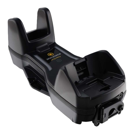
POWERSCAN™ BC96XX BASE STATIONS USING THE BC96XX BASE STATION The BC96XX base station, when paired with one or more PowerScan™ PM96XX readers, builds a Cordless Reading System for the collection, decod- ing and transmission of bar code data. It can be connected to a Host PC via RS232, USB, USB Type C, or Ethernet, depending on the interchangeable con- nection box. -
Page 10: Base Station Models
base station Models BASE STATION MODELS Each base station is composed of a cradle which must be connected to a con- nection box, depending on the interface desired and on the IP (water and dust) protection grade. The base station and connection box models are listed below. Base Station Models BC9600-433 BASE/CHARGER 433MHZ w/o conn. -
Page 11: Mounting Instructions
Mounting Instructions MOUNTING INSTRUCTIONS The base station can be either set on or mounted to a flat surface for desktop usage, or affixed vertically to a wall. Depending on the model, the appropriate connection box is already installed. PERMANENT MOUNTING For either desktop or wall mounting, the base station can be fastened directly to a flat surface using screws (not included). -
Page 12: Wall Mounting
Wall Mounting WALL MOUNTING The base station contains a reversible positioning tab for horizontal or vertical mounting. Figure 1 - Positioning Tab Desktop Positioning Tab (Horizontal) Wall Positioning Tab (Vertical) When shipped, the base station has the positioning tab installed in the Desktop position (horizontal). - Page 13 Wall Mounting 3. Rotate the tab until you will see "WALL" tooth, put the rotated tab into place and secure it with the screw. 4. Remove the label (indicated in the figure below) from the base station: 5. Mount the Wall Mounting bracket onto the base station. QUICK REFERENCE GUIDE...
-
Page 14: Portable Desktop Mounting
Portable Desktop Mounting PORTABLE DESKTOP MOUNTING For desktop mounting, if portability of the base station is required, the mounting plate can be used. There are two ways this can be done: (1) base station fast release by first fixing the mounting plate onto a flat surface so the base station can be slid off and on, or (2) connection box fast release by fixing the mounting plate to the connection box and then fixing both of them onto a flat surface so only the cradle can be slid off while the connection box will... - Page 15 Portable Desktop Mounting 3. Align the base station with the mounting plate until you see the sphere inside the bigger hole on the left. 4. Move the base station down until the sphere is aligned with the smaller hole. QUICK REFERENCE GUIDE...
-
Page 16: Connection Box Fast Release - Mounting The Bracket
Portable Desktop Mounting Connection Box Fast Release - Mounting the Bracket 1. Remove the protective strips. 2. Unscrew the connection box from the base station. 3. Screw the mounting plate to the connection box. 4. Unlock the lever and remove the connection box from the base station. 5. - Page 17 Portable Desktop Mounting 6. With the lever still unlocked, align the base station with the connection box until you see the sphere inside the bigger hole on the right. 7. Move the base station up until the sphere is aligned with the smaller hole, then lock the lever to secure the connection box.
-
Page 18: System Connections
System Connections SYSTEM CONNECTIONS CAUTION: Connections should always be made with power off. The BC9630 (BC9600 + CM9630 connection box) provides a multi-interface connector for connections to a host and a power supply connector for an external power supply. To unlock the multi-interface cable, first lift the lever and then extract the cable, as indicated by the label next to the lever. - Page 19 System Connections RS232 BC9630 BC9631 The power supply is optional, the base station can be powered by the USB port. In this case, the full charging of an empty battery will take about 16 hours with an approved USB cable (type A) and 6.5 hours with an approved USB cable (type C) at ambient temperature.
-
Page 20: Connecting And Disconnecting The Cables
System Connections BC9631 ETHERNET BC9680 Connecting and Disconnecting the Cables Connecting BC9630 cables Connect the multi-interface cable first, then connect the power adapter cable. Finally, power on the base station. BC96XX BASE STATIONS... -
Page 21: Disconnecting Bc9630 Cables
System Connections After connecting the power supply cable, secure it on the strain relief as shown in the figure below. Disconnecting BC9630 cables To disconnect the cables, power off the base station, unlock the lever and press down the cable clip using a pen or a similar tool. Unlock the lever Press down the Cable clip... -
Page 22: Connecting Bc9631 Multi-Interface Cable
System Connections Pull out the multi-interface cable and put the lever back into lock position. Lock position Connecting BC9631 multi-interface cable Unscrew the no-tool screw to open the front door, connect the multi-inter- face cable, close the door and screw it back. Unscrew Insert Screw... -
Page 23: Connecting Bc9680 Cables
System Connections Connecting BC9680 cables Connect the Ethernet cable and then connect the power adapter cable. Finally, power on the cradle and lock the power cable on the strain relief. To disconnect the cables, first unlock the power cable and then pull it out. To disconnect the Ethernet cable, use a flat screwdriver to unlock the Ethernet clip. -
Page 24: Configuration
RS232/USB-COM or Ethernet interface. It also allows upgrading the software of the connected device (see the Datalogic Aladdin™ Help On-Line for more details). Serial Configuration By connecting the BC963X to a PC through an RS232 or USB-COM interface cable, it is possible to send configuration strings from the PC to the BC963X. -
Page 25: Technical Specifications
Technical Specifications TECHNICAL SPECIFICATIONS The following table contains Physical and Performance Characteristics, User Environment and Regulatory information. PHYSICAL CHARACTERISTICS Color Black Height 9.8 cm (3.9'') Dimensions Length 24.3 cm (9.6'') Width 10.2 cm (4'') Weight BC9630 (w/o cable): 590 g (without cable) BC9631 (w/o cable): 600 g ELECTRICAL CHARACTERISTICS... -
Page 26: Technical Support
TECHNICAL SUPPORT Support Through the Website Datalogic provides several services as well as technical support through its website. Log on to (www.datalogic.com). For quick access, from the home page click on the search icon , and type in the name of the product you’re looking for. -
Page 27: Warranty
The Warranty Period shall be three years from the date of shipment by Datalogic, unless otherwise agreed in an applicable writing by Datalogic. Datalogic will not be liable under the warranty if the Product has been exposed or subjected to any: (1) maintenance, repair, installation, handling, packaging, transportation, storage, operation or use that is improper or otherwise not in compliance with Datalogic’s instruction;... - Page 28 ©2022 Datalogic S.p.A. and /or its affiliates. • All rights reserved • Without limiting the rights under copyright, no part of this documentation may be reproduced, stored in or introduced into a retrieval system, or transmitted in any form or by any means, or for any purpose, without the express written permission of Datalogic S.p.A.
Need help?
Do you have a question about the PowerScan BC96 Series and is the answer not in the manual?
Questions and answers